HELICOPTERS NSN 1520-01-035-0266, NSN 1520-01-082-0686, NSN 1520-01-298-4532. REPAIR STANDARDS (2004) - page 4
DMWR 1-1520-237
(b)
Locate and temporarily install doubler (70070-20587-102), stiffener (70070-20587-104), clip (70070-
20587-106), and radius block (SS1058A7-26-13) as shown (Sheet 2, Zones 10-E, 11-E, 14-C, and 15-E).
(c)
Drill fastener holes, as shown (Sheet 2, Zones 9-D, 10-C, 10-D, 11-C, and 11-D).
(d)
Remove temporarily installed doubler (70070-20587-102), stiffener (70070-20587-104), clip (70070-
20587-106), and radius block (SS1058A7-26-13), deburr and touch up, as required.
WARNING
OBSERVE ALL CAUTIONS AND WARNINGS ON CONTAINERS WHEN USING CONSUMABLES.
WHEN APPLICABLE, WEAR NECESSARY PROTECTIVE GEAR DURING HANDLING AND USE. IF A
CONSUMABLE IS FLAMMABLE OR EXPLOSIVE, MAKE CERTAIN CONSUMABLE AND ITS VAPORS ARE
KEPT AWAY FROM HEAT, SPARK, AND FLAME. MAKE CERTAIN EQUIPMENT IS PROPERLY
GROUNDED AND FIREFIGHTING EQUIPMENT IS READILY AVAILABLE PRIOR TO USE. FOR AD-
DITIONAL INFORMATION ON TOXICITY, FLASHPOINT, AND FLAMMABILITY OF CHEMICALS,
CONSULT YOUR MEDICAL PEOPLE, OR MANUFACTURER OF THE CONSUMABLE.
(e)
Install doubler (70070-20587-102) wet with sealant (AMS-S-8802 A2, or equivalent) using fasteners
shown (Sheet 2, Zones 9-E, 10-C, 10-E, and 11-C through 11-E).
(f)
Install stiffener (70070-20587-104), clip (70070-20587-106), and radius block (SS1058A7-26-13) using
fasteners shown (Sheet 2, Zones 10-E, 14-D, and 14-F).
WARNING
OBSERVE ALL CAUTIONS AND WARNINGS ON CONTAINERS WHEN USING CONSUMABLES.
WHEN APPLICABLE, WEAR NECESSARY PROTECTIVE GEAR DURING HANDLING AND USE. IF A
CONSUMABLE IS FLAMMABLE OR EXPLOSIVE, MAKE CERTAIN CONSUMABLE AND ITS VAPORS ARE
KEPT AWAY FROM HEAT, SPARK, AND FLAME. MAKE CERTAIN EQUIPMENT IS PROPERLY
GROUNDED AND FIREFIGHTING EQUIPMENT IS READILY AVAILABLE PRIOR TO USE. FOR AD-
DITIONAL INFORMATION ON TOXICITY, FLASHPOINT, AND FLAMMABILITY OF CHEMICALS,
CONSULT YOUR MEDICAL PEOPLE, OR MANUFACTURER OF THE CONSUMABLE.
(g)
Reinstall fasteners wet with sealant (AMS-S-8802, A2 or equivalent) at locations shown (Sheet 2, Zones
11-B, 11-D, 11-F, 12-C through 12-E, and Notes 5, 7, and 8).
(h)
Remove and replace fasteners wet with sealant (AMS-S-8802, A2 or equivalent) at locations shown (Sheet
2, Zones 5-E through 5-G, 6-E through 6-G, 9-F, and Note 5).
(i)
Reinstall pneumatic lines previously removed.
C.
Reinstallation of removed equipment:
(1)
Install removed equipment per reference (a).
D.
Record of Compliance:
(1)
Make an appropriate logbook entry to show compliance with this Special Service Instruction.
E-233
DMWR 1-1520-237
Weight and Balance Data:
POUNDS
INCHES AFT
MOMENT/
QTY
PART NO.
NOMENCLATURE
WEIGHT
OF DATUM
1000
1
70070-20587-011
Mod. Kit
+1.8
653.7
1.177
Weight and Balance: Change resulting from these instructions are as follows:
Change in basic weight:
+1.8 pounds
Moment arm:
653.7 in.
Change in basic moment/1000:
1.177
Manpower (Estimated)
No. of Personel
No. of Hours
Man-hours
Sheet Metal Mechanic
1
24.0
*24.0
*Does not include time required to prepare helicopter or return it to flight status.
Material Information:
A.
Modification Kit Required:
Qty
Nomenclature
Part Number
Source
1
Mod. Kit, Side Skin,
70070-20587-011
(1)
consisting of:
1
Mod. Kit, Plating Instl,
70070-20587-015
consisting of:
41
Collar
HL1087A-6
3
Collar
HL1087A-8
26
Pin, Hi-Lok
HL64PB-6-3
5
Pin, Hi Lok
HL64PB-6-4
1
Pin, Hi-Lok
HL64PB-6-5
4
Pin
HL64PB-6-6
5
Pin, Hi Lok
HL64PB-6-7
3
Pin
HL64PB-8-8
30
Rivet
MS20470AD4-2
15
Rivet
MS20470AD5-3
E-234
DMWR 1-1520-237
Qty
Nomenclature
Part Number
Source
2
Rivet
MS20470AD5-7
8
Rivet
MS20470AD6-5
1
Radius Block
SS1058A7-26-13
1
Doubler
70070-20587-101
1
Stiffener
70070-20587-103
1
Clip
70070-20587-105
1
Mod. Kit, Plating Instl,
70070-20587-016
consisting of:
47
Collar
HL1087A-6
3
Collar
HL1087A-8
30
Pin, Hi-Lok
HL64PB-6-3
6
Pin, Hi Lok
HL64PB-6-4
1
Pin, Hi-Lok
HL64PB-6-5
5
Pin
HL64PB-6-6
5
Pin, Hi Lok
HL64PB-6-7
3
Pin
HL64PB-8-8
30
Rivet
MS20470AD4-2
15
Rivet
MS20470AD5-3
2
Rivet
MS20470AD5-7
8
Rivet
MS20470AD6-5
1
Radius Block
SS1058A7-26-13
1
Doubler
70070-20587-102
1
Stiffener
70070-20587-104
1
Clip
70070-20587-106
1
Mod. Kit, Spar Instl,
70070-20587-017
consisting of:
3
Rivet
MS20470AD6-6
3
Pin, SWG LKG
NAS1526-06
E-235
DMWR 1-1520-237
B.
Consumable Material:
WARNING
OBSERVE ALL CAUTIONS AND WARNINGS ON CONTAINERS WHEN USING CONSUMABLES.
WHEN APPLICABLE, WEAR NECESSARY PROTECTIVE GEAR DURING HANDLING AND USE. IF A
CONSUMABLE IS FLAMMABLE OR EXPLOSIVE, MAKE CERTAIN CONSUMABLE AND ITS VAPORS ARE
KEPT AWAY FROM HEAT, SPARK, AND FLAME. MAKE CERTAIN EQUIPMENT IS PROPERLY
GROUNDED AND FIREFIGHTING EQUIPMENT IS READILY AVAILABLE PRIOR TO USE. FOR AD-
DITIONAL INFORMATION ON TOXICITY, FLASHPOINT, AND FLAMMABILITY OF CHEMICALS,
CONSULT YOUR MEDICAL PEOPLE, OR MANUFACTURER OF THE CONSUMABLE.
Qty
Nomenclature
Part Number
Source
8 oz.
Sealant
AMS-S-8802, A2 or equivalent
(1)
C.
Source:
(1)
Available through normal supply channels
E-236
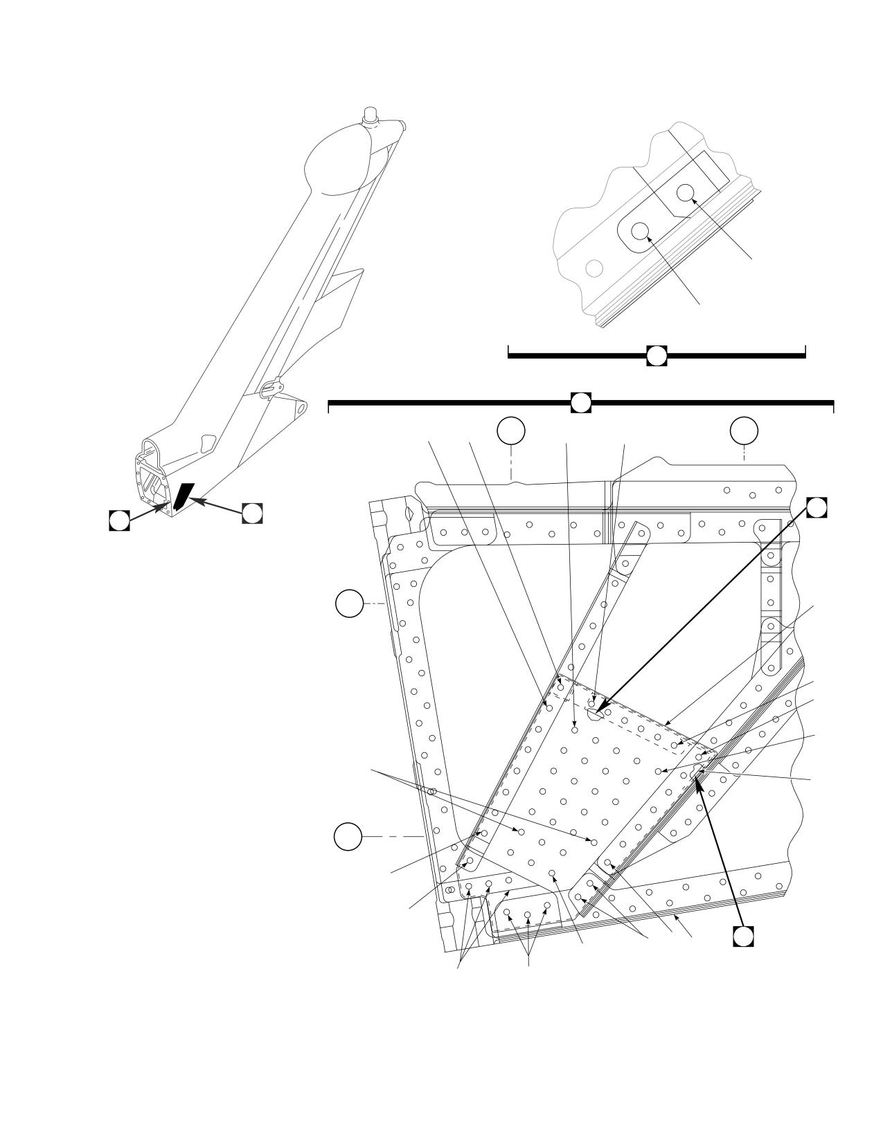
DMWR 1-1520-237
4
3
2
A
STA
STA
9
10
650
11
9
660
B
A
C
WL
230
16
9
12
11
11
1
WL
220
9
7
8
8 12
5
2
11
12
6
8
14
15
AB3120_1
13
SA
Figure E-24. Side Skin Modification Kit (Sheet 1 of 2)
E-237
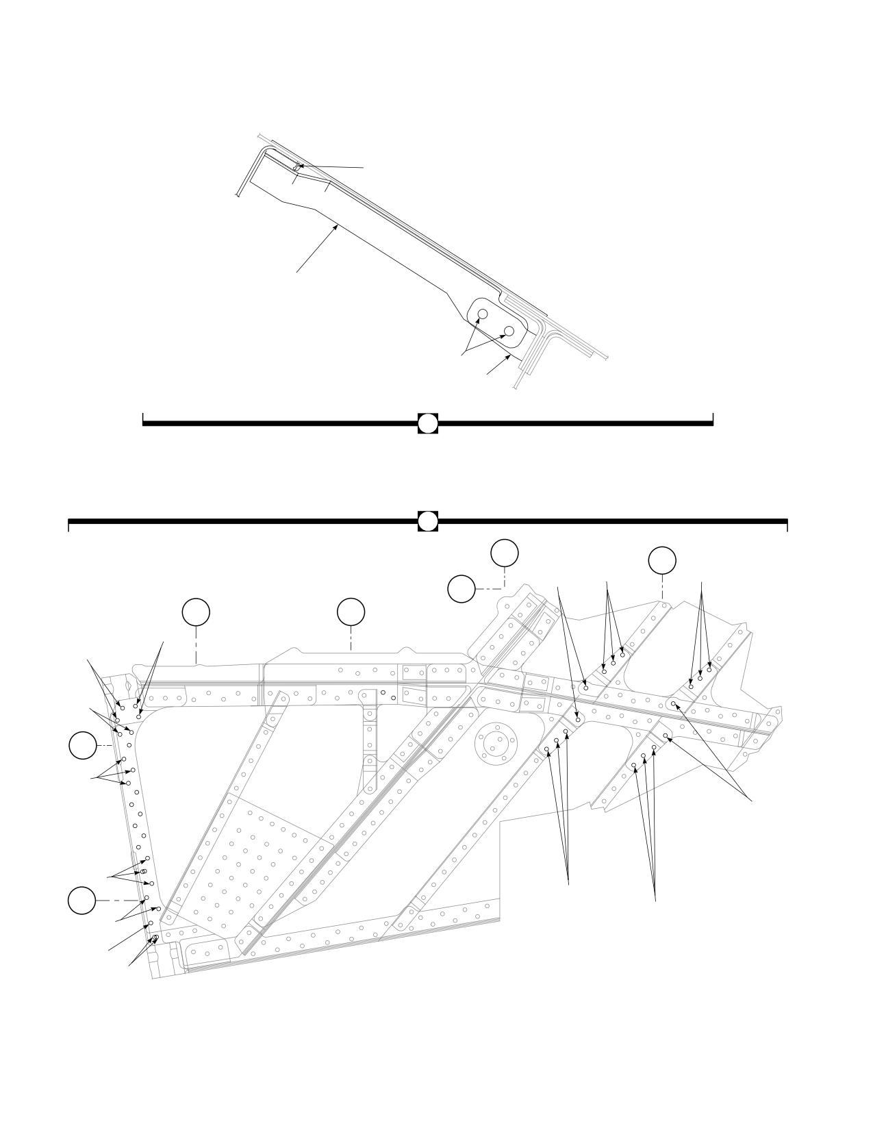
DMWR 1-1520-237
19
18
9
17
B
C
STA
670
STA
8
680
8
8
20
20
21
WL
230
STA
STA
650
660
8
22
8
22
8
20
WL
230
8
20
8
21
8
20
WL
8
220
20
8
8
20
20
8
21
8
22
AB3120_2
SA
Figure E-24. Side Skin Modification Kit (Sheet 2 of 2)
E-238
DMWR 1-1520-237
QTY
USABLE
FIGURE &
PER
ON
INDEX NO.
PART NUMBER
1 2 3 4 5 6 7
DESCRIPTION
ASSY
CODE
E-24-
70070-20587-011
SIDE SKIN MODIFICATION KIT
REF
-1
70070-20587-017
M/K SPAR INSTL
1
-2
70070-20587-023
. SPAR INSTL, (Modified from 70203-06051-012) .
REF
-3
MS20470AD6-6
. RIVET
3
-4
NAS1526-06
. SWAGE LOCKING PIN
3
-5
70070-20587-015
M/K PLTG INSTL, LH
1
70070-20587-016
M/K PLTG INSTL, RH
1
-6
70070-20587-012
PLATING INSTL, (Modified from 70203-06050-
011)
REF
70070-20587-013
PLATING INSTL, (Modified from 70203-06050-
013)
REF
70070-20587-014
PLATING INSTL, (Modified from 70203-06050-
015)
REF
70070-20587-018
PLATING INSTL, (Modified from 70203-06050-
018)
REF
70070-20587-019
PLATING INSTL, (Modified from 70203-06050-
012)
REF
70070-20587-020
PLATING INSTL, (Modified from 70203-06050-
014)
REF
70070-20587-021
PLATING INSTL, (Modified from 70203-06050-
016)
REF
70070-20587-022
PLATING INSTL, (Modified from 70203-06050-
017)
REF
-7
HL64PB-6-5
HI-LOK PIN, (73197)
1
-8
HL1087A-6
COLLAR, (73197) (Used on 70070-20587-015)..
41
HL1087A-6
COLLAR, (73197) (Used on 70070-20587-016)..
47
-9
MS20470AD5-3
RIVET
15
-10
MS20470AD5-7
RIVET
2
-11
MS20470AD4-2
RIVET
30
-12
MS20470AD6-5
RIVET
8
-13
HL64PB-6-7
HI-LOK PIN, (73197)
5
-14
HL64PB-8-8
PIN
3
-15
HL1087A-8
COLLAR, (73197)
3
-16
70070-20587-101
DOUBLER, (Used on 70070-20587-015)
1
70070-20587-102
DOUBLER, (Used on 70070-20587-016)
1
-17
70070-20587-105
CLIP, (Used on 70070-20587-015)
1
70070-20587-106
CLIP, (Used on 70070-20587-016)
1
-18
70070-20587-103
STIFFENER, (Used on 70070-20587-015)
1
70070-20587-104
STIFFENER, (Used on 70070-20587-016)
1
-19
SS1058A7-26-13
RADIUS BLOCK
1
-20
HL64PB-6-3
HI-LOK PIN, (73197) (Used on 70070-20587-
015)
26
HL64PB-6-3
HI-LOK PIN, (73197) (Used on 70070-20587-
016)
30
-21
HL64PB-6-4
HI-LOK PIN, (73197) (Used on 70070-20587-
015)
5
HL64PB-6-4
HI-LOK PIN, (73197) (Used on 70070-20587-
016)
6
-22
HL64PB-6-6
PIN, (73197)
4
E-239
DMWR 1-1520-237
E-21. AFT SPAR FT MODIFICATION KIT (50-25).
Subject: Tail Rotor Pylon, Aft Spar Stabilator Attachment Fitting, Modification of, dated 31 March 2003
Purpose: Provide instructions to remove bushings and install new Forcemate bushings and spherical bearings at the tail
rotor pylon aft spar attachment location.
Model:
UH-60A
Description: The stabilator attachment fittings are reworked by removing bushings and liners and installing new Force-
mate bushings and spherical bearings.
Drawings required for modification:
70070-20588
References: (a) Special Service Instructions (SSI) No. 50-31, Installation of 9A to A9 Recapitalization Program, dated
March 31, 2003
(b) Technical Manual (TM) 1-1520-237-23, Aviation Unit And Intermediate Maintenance For Army
Models UH-60A, UH-60L, EH-60A, and UH-60Q Helicopters, Chapter 2, Airframe
(c) Fatigue Technologies Inc., FAN-718, dated March 4, 2002
(d) TM 1-1520-265-23, Technical Manual, Aviation Unit Maintenance (AVUM) and Aviation Intermedi-
ate (AVIM) Manual, Nondestructive Inspection Procedures for H-60 Helicopter Series
(e) TM 1-1500-335-23, Technical Manual, Nondestructive Inspection Methods
Instructions:
NOTE
• AcompletereviewofthisSSIisrecommendedbeforeincorporatingthetailrotorpylonstabilatorattach-
ment fitting modification kit.
• Before beginning this modification procedure, use the material information list to inventory the modification
kit. Make sure all parts are present and in serviceable condition.
• Where drawing numbers are not listed within individual step(s), drawing(s) listed in preceding step(s) are
the controlling authority.
• The sheet metal and structural modifications in this SSI shall be done by personnel experienced in reading
modification drawings. Routine steps such as cleaning, layout and drilling, deburring, standard repairs,
corrosion control, clean up after rework, chemical coating for aluminum after cutting/trimming parts, paint
touch up, and safety practices may not be called out herein. However, these steps and all other required
routine tasks shall be done.
• Slight variations to the instructions contained herein are allowed, as long as the intent of the modification
is accomplished.
E-240
DMWR 1-1520-237
• During rework refer to reference (c) as required.
A.
Preparation for modification and removal of equipment:
(1)
Confirm that all warnings, cautions, and notes are complied with per reference (a).
(2)
Perform preparation for modification per reference (a).
WARNING
FLIGHT SAFETY PART
TAIL ROTOR PYLON STABILATOR ATTACHMENT FITTING CONTAINS CRITICAL CHARACTERISTICS
WHICH MUST NOT BE DAMAGED DURING REMOVAL AND REWORK. USE EXTREME CAUTION DUR-
ING REMOVAL AND REWORK.
B.
Modification, tail rotor pylon, aft spar assembly (70202-06052-041, -043, -044, or -045) stabilator attachment
fitting:
(1)
Modification of left side attachment fitting assembly (70209-06052-041) as follows (Dwg 70070-20588):
(a)
Remove two bushings (NAS538-10P024) and one bushing (NAS537-10P062) using bearing removal/
installation tool (70700-20129-041) (Sheet 2, Zones 6-G and 6-E).
WARNING
OBSERVE ALL CAUTIONS AND WARNINGS ON CONTAINERS WHEN USING CONSUMABLES.
WHEN APPLICABLE, WEAR NECESSARY PROTECTIVE GEAR DURING HANDLING AND USE. IF A
CONSUMABLE IS FLAMMABLE OR EXPLOSIVE, MAKE CERTAIN CONSUMABLE AND ITS VAPORS ARE
KEPT AWAY FROM HEAT, SPARK, AND FLAME. MAKE CERTAIN EQUIPMENT IS PROPERLY
GROUNDED AND FIREFIGHTING EQUIPMENT IS READILY AVAILABLE PRIOR TO USE. FOR AD-
DITIONAL INFORMATION ON TOXICITY, FLASHPOINT, AND FLAMMABILITY OF CHEMICALS,
CONSULT YOUR MEDICAL PEOPLE, OR MANUFACTURER OF THE CONSUMABLE.
(b)
Clean lug bore surfaces using cheesecloth cloth (CCC-C-440 or equivalent) and 1,1,1- trichloroethane
(MIL-T-81533 or equivalent).
(c)
Inspect for damage to critical areas (minimum thickness and minimum area) of stabilator attachment fitting
(70209-06052-101 or -103) and repair as required (Sheet 2, View F, Zone 11-G, Note 10; Sheet 3, Note 43).
(d)
Inspect fitting assembly (70209-06052-041) bores and measure diameters. Line ream hole to 0.8120 -
0.8130-inch diameter nominal. See Sheet 2, Note 7 for over sized holes (Sheet 2, Zone 7-G, Notes 7 and 12; Sheet 3,
Note 32).
(e)
Break all sharp edges of line reamed holes.
E-241
DMWR 1-1520-237
WARNING
OBSERVE ALL CAUTIONS AND WARNINGS ON CONTAINERS WHEN USING CONSUMABLES.
WHEN APPLICABLE, WEAR NECESSARY PROTECTIVE GEAR DURING HANDLING AND USE. IF A
CONSUMABLE IS FLAMMABLE OR EXPLOSIVE, MAKE CERTAIN CONSUMABLE AND ITS VAPORS ARE
KEPT AWAY FROM HEAT, SPARK, AND FLAME. MAKE CERTAIN EQUIPMENT IS PROPERLY
GROUNDED AND FIREFIGHTING EQUIPMENT IS READILY AVAILABLE PRIOR TO USE. FOR AD-
DITIONAL INFORMATION ON TOXICITY, FLASHPOINT, AND FLAMMABILITY OF CHEMICALS,
CONSULT YOUR MEDICAL PEOPLE, OR MANUFACTURER OF THE CONSUMABLE.
(f)
Perform liquid penetrant or Eddy Current inspection of holes (Sheet 2, Note 13 and reference (d) and (e)).
(g)
Inspect for damage to critical areas (minimum thickness and minimum area) of stabilator attachment fitting
(70209-06052-101 or -103) and repair as required (Sheet 2, View F, Zone 11-G, Note 10; Sheet 3, Note 43).
WARNING
OBSERVE ALL CAUTIONS AND WARNINGS ON CONTAINERS WHEN USING CONSUMABLES.
WHEN APPLICABLE, WEAR NECESSARY PROTECTIVE GEAR DURING HANDLING AND USE. IF A
CONSUMABLE IS FLAMMABLE OR EXPLOSIVE, MAKE CERTAIN CONSUMABLE AND ITS VAPORS ARE
KEPT AWAY FROM HEAT, SPARK, AND FLAME. MAKE CERTAIN EQUIPMENT IS PROPERLY
GROUNDED AND FIREFIGHTING EQUIPMENT IS READILY AVAILABLE PRIOR TO USE. FOR AD-
DITIONAL INFORMATION ON TOXICITY, FLASHPOINT, AND FLAMMABILITY OF CHEMICALS,
CONSULT YOUR MEDICAL PEOPLE, OR MANUFACTURER OF THE CONSUMABLE.
(h)
Apply alodine 1200S or equivalent and apply primer (EA9203 or equivalent) to reworked area (Sheet 2,
Note 14).
NOTE
Allow primer (EA9203 or equivalent) to dry before proceeding to next step.
(i)
Install bushing (FMI-718-45010-A) inner on fitting assembly (70209-06052-041). See Sheet 2, Note 7 for
over sized bushing (Sheet 2, Zone 6-G, Note 8; Sheet 3, Note 32).
(j)
Perform axial load proof test on inner shoulder bushing (FMI-718-45010-A) (Sheet 2, Zone 5-G, Note 11).
RESULT: Verify bushing or bearing does not move.
(k)
Install nominal bushing (FMI-718-45030-A) outer on fitting assembly (70209-06052-041). See Sheet 2,
Note 7 for over sized bushing (Sheet 2, Zone 6-E, Note 8; Sheet 3, Note 32).
(l)
Perform axial load proof test on inboard end of nominal bushing (FMI-718-45030-A) (Sheet 2, Zones 5-E,
5-G, 6-E, and 6-G, Note 11).
RESULT: Verify movement of bushing at or below 2000 pound force.
(m)
Line ream hole to 0.6250 - 0.6265-inch diameter (Sheet 2, Zone 7-G).
E-242
DMWR 1-1520-237
(n)
Chamfer (inside only) both edges of bushings (FMI-718-45010-A and FMI-718-45030-A) 0.015 / 0.030
x 45 degrees (Sheet 2, Details B and E, Zones 5-C and 7-C).
WARNING
OBSERVE ALL CAUTIONS AND WARNINGS ON CONTAINERS WHEN USING CONSUMABLES.
WHEN APPLICABLE, WEAR NECESSARY PROTECTIVE GEAR DURING HANDLING AND USE. IF A
CONSUMABLE IS FLAMMABLE OR EXPLOSIVE, MAKE CERTAIN CONSUMABLE AND ITS VAPORS ARE
KEPT AWAY FROM HEAT, SPARK, AND FLAME. MAKE CERTAIN EQUIPMENT IS PROPERLY
GROUNDED AND FIREFIGHTING EQUIPMENT IS READILY AVAILABLE PRIOR TO USE. FOR AD-
DITIONAL INFORMATION ON TOXICITY, FLASHPOINT, AND FLAMMABILITY OF CHEMICALS,
CONSULT YOUR MEDICAL PEOPLE, OR MANUFACTURER OF THE CONSUMABLE.
(o)
Fillet seal inboard side of bushing (FMI-718-45010-A) inner using sealing compound (AMS3265 or
equivalent) (Sheet 2, Zone 8-G; Sheet 3, Note 19).
(p)
Apply coating of antiseize compound (MIL-T-83483 or equivalent) to inner bores of bushings (Sheet 3,
Note 24).
(q)
Reidentify fitting assembly (70209-06052-041) to (70070-20588-043) with pen and contrasting ink
(Sheet 1, Note 4).
(2)
Modification of right side attachment fitting assembly (70209-06052-043 or -046) as follows (Dwg 70070-
20588):
(a)
Remove bearing (B5539WZZ) or sherical bearings (KNDB 12-25) from fitting assembly (70209-06052-
043 or -046) using bearing removal/installation tool (70700-20129-041). If bearing is roller staked remove staking
flanges on outside of race by rotating arbor and cutter while applying light pressure until cutter has penetrated stake
0.020-inch (Sheet 2, Zones 13-E and 13-G; Sheet 1, Notes 1 and 2).
(b)
Remove four liners (70209-06052-104) using a drift and mallet from fitting assembly (70209-06052-043
or -046) (Sheet 2, Zones 13-E and 13-G; Sheet 3, Note 30).
(c)
Remove remaining adhesive using a nonmetallic scraper and/or abrasive mat (MIL-A-9962 or
equivalent).
WARNING
OBSERVE ALL CAUTIONS AND WARNINGS ON CONTAINERS WHEN USING CONSUMABLES.
WHEN APPLICABLE, WEAR NECESSARY PROTECTIVE GEAR DURING HANDLING AND USE. IF A
CONSUMABLE IS FLAMMABLE OR EXPLOSIVE, MAKE CERTAIN CONSUMABLE AND ITS VAPORS ARE
KEPT AWAY FROM HEAT, SPARK, AND FLAME. MAKE CERTAIN EQUIPMENT IS PROPERLY
GROUNDED AND FIREFIGHTING EQUIPMENT IS READILY AVAILABLE PRIOR TO USE. FOR AD-
DITIONAL INFORMATION ON TOXICITY, FLASHPOINT, AND FLAMMABILITY OF CHEMICALS,
CONSULT YOUR MEDICAL PEOPLE, OR MANUFACTURER OF THE CONSUMABLE.
(d)
Clean lug bore surfaces using cheesecloth cloth (CCC-C-440 or equivalent) and 1,1,1- trichloroethane
(MIL-T-81533 or equivalent).
E-243
DMWR 1-1520-237
(e)
Inspect for damage to critical areas (minimum thickness and minimum area) of stabilator attachment fitting
(70209-06052-101 or -103) and repair as required (Sheet 2, View F, Zone 11-G, Note 10; Sheet 3, Note 43).
(f)
Inspect fitting assembly (70209-06052-043 or -046) bores and measure diameters. Line ream hole to
1.2523 - 1.2533-inch diameter nominal. See Sheet 2, Note 7 for over sized holes (Sheet 2, Zone 14-G, Notes 7 and 12;
Sheet 3, Note 32).
WARNING
OBSERVE ALL CAUTIONS AND WARNINGS ON CONTAINERS WHEN USING CONSUMABLES.
WHEN APPLICABLE, WEAR NECESSARY PROTECTIVE GEAR DURING HANDLING AND USE. IF A
CONSUMABLE IS FLAMMABLE OR EXPLOSIVE, MAKE CERTAIN CONSUMABLE AND ITS VAPORS ARE
KEPT AWAY FROM HEAT, SPARK, AND FLAME. MAKE CERTAIN EQUIPMENT IS PROPERLY
GROUNDED AND FIREFIGHTING EQUIPMENT IS READILY AVAILABLE PRIOR TO USE. FOR AD-
DITIONAL INFORMATION ON TOXICITY, FLASHPOINT, AND FLAMMABILITY OF CHEMICALS,
CONSULT YOUR MEDICAL PEOPLE, OR MANUFACTURER OF THE CONSUMABLE.
(g)
Perform liquid penetrant or Eddy Current inspection of holes (Sheet 2, Note 13 and reference (d) and (e)).
(h)
Line ream holes to applicable size.
(i)
Chamfer both edges of fitting assembly (70209-06052-043 or -046) 0.045 / 0.035 x 45 degrees (Sheet
2, Detail D, Zone 15-B).
WARNING
OBSERVE ALL CAUTIONS AND WARNINGS ON CONTAINERS WHEN USING CONSUMABLES.
WHEN APPLICABLE, WEAR NECESSARY PROTECTIVE GEAR DURING HANDLING AND USE. IF A
CONSUMABLE IS FLAMMABLE OR EXPLOSIVE, MAKE CERTAIN CONSUMABLE AND ITS VAPORS ARE
KEPT AWAY FROM HEAT, SPARK, AND FLAME. MAKE CERTAIN EQUIPMENT IS PROPERLY
GROUNDED AND FIREFIGHTING EQUIPMENT IS READILY AVAILABLE PRIOR TO USE. FOR AD-
DITIONAL INFORMATION ON TOXICITY, FLASHPOINT, AND FLAMMABILITY OF CHEMICALS,
CONSULT YOUR MEDICAL PEOPLE, OR MANUFACTURER OF THE CONSUMABLE.
(j)
Perform liquid peneterant or Eddy Current inspection of holes (Sheet 2, Note 13 and reference (d) and (e)).
(k)
Inspect for damage to critical areas (minimum thickness and minimum area) of stabilator attachment fitting
(70209-06052-101 or -103) and repair as required (Sheet 2, View F, Zone 11-G, Note 10; Sheet 3, Note 43).
E-244
DMWR 1-1520-237
WARNING
OBSERVE ALL CAUTIONS AND WARNINGS ON CONTAINERS WHEN USING CONSUMABLES.
WHEN APPLICABLE, WEAR NECESSARY PROTECTIVE GEAR DURING HANDLING AND USE. IF A
CONSUMABLE IS FLAMMABLE OR EXPLOSIVE, MAKE CERTAIN CONSUMABLE AND ITS VAPORS ARE
KEPT AWAY FROM HEAT, SPARK, AND FLAME. MAKE CERTAIN EQUIPMENT IS PROPERLY
GROUNDED AND FIREFIGHTING EQUIPMENT IS READILY AVAILABLE PRIOR TO USE. FOR AD-
DITIONAL INFORMATION ON TOXICITY, FLASHPOINT, AND FLAMMABILITY OF CHEMICALS,
CONSULT YOUR MEDICAL PEOPLE, OR MANUFACTURER OF THE CONSUMABLE.
(l)
Apply alodine 1200S or equivalent and apply primer (EA9203 or equvalent) to reworked area (Sheet 2,
Note 14).
NOTE
Allow primer (EA9203 or equivalent) to dry before proceeding to next step.
(m)
Install two bushings (FMI-718-45020-A) on fitting assembly (70209-06052-043 or -046). See Sheet 2,
Note 7 for over sized bushings (Sheet 2, Zones 12-E and 12-F, Notes 8 and 16; Sheet 3, Note 32).
(n)
Inspect bushings (FMI-718-45020-A) for flushness (+0.010 / -0.010) after installation (Sheet 3, Note 33).
(o)
Line ream hole to 1.1870 - 1.1875-inch diameter (Sheet 2, Zone 14-H).
(p)
Chamfer (inside only) both edges of bushings (FMI-718-45020-A) 0.045 / 0.035 x 45 degrees (Sheet 2,
Detail D, Zone 15-B).
WARNING
OBSERVE ALL CAUTIONS AND WARNINGS ON CONTAINERS WHEN USING CONSUMABLES.
WHEN APPLICABLE, WEAR NECESSARY PROTECTIVE GEAR DURING HANDLING AND USE. IF A
CONSUMABLE IS FLAMMABLE OR EXPLOSIVE, MAKE CERTAIN CONSUMABLE AND ITS VAPORS ARE
KEPT AWAY FROM HEAT, SPARK, AND FLAME. MAKE CERTAIN EQUIPMENT IS PROPERLY
GROUNDED AND FIREFIGHTING EQUIPMENT IS READILY AVAILABLE PRIOR TO USE. FOR AD-
DITIONAL INFORMATION ON TOXICITY, FLASHPOINT, AND FLAMMABILITY OF CHEMICALS,
CONSULT YOUR MEDICAL PEOPLE, OR MANUFACTURER OF THE CONSUMABLE.
(q)
Install two sherical bearings (KNDB 12-25) wet with sealing compound (CA1000 or equivalent) on fitting
assembly (70209-06052-043 or -046) and roller stake (Sheet 2, Zones 13-E and 13-F, Note 9).
(r)
Perform axial test on sherical bearings (KNDB 12-25) (Sheet 2, Zones 13-E and 13-F, Note 11).
RESULT: Verify bushing or bearing does not move.
(s)
Check for alignment after staking and check for rotational movement after staking with finger pressure
(Sheet 3, Notes 34 and 35).
E-245
DMWR 1-1520-237
WARNING
OBSERVE ALL CAUTIONS AND WARNINGS ON CONTAINERS WHEN USING CONSUMABLES.
WHEN APPLICABLE, WEAR NECESSARY PROTECTIVE GEAR DURING HANDLING AND USE. IF A
CONSUMABLE IS FLAMMABLE OR EXPLOSIVE, MAKE CERTAIN CONSUMABLE AND ITS VAPORS ARE
KEPT AWAY FROM HEAT, SPARK, AND FLAME. MAKE CERTAIN EQUIPMENT IS PROPERLY
GROUNDED AND FIREFIGHTING EQUIPMENT IS READILY AVAILABLE PRIOR TO USE. FOR AD-
DITIONAL INFORMATION ON TOXICITY, FLASHPOINT, AND FLAMMABILITY OF CHEMICALS,
CONSULT YOUR MEDICAL PEOPLE, OR MANUFACTURER OF THE CONSUMABLE.
(t)
Seal groves between fitting assembly (70209-06052-043 or -046), bushing (FMI-718-45020-A), and
sherical bearing (KNDB 12-25) using sealing compound (AMS3265 or equivalent) (Sheet 2, Zones 13-E and 13-F, Note
16).
(u)
Reidentify fitting (70209-06052-044) to (70070-20588-044) with pen and contrasting ink (Sheet 3, Note
36).
(v)
Reidentify fitting assembly (70209-06052-043 or -046) to (70070-20588-041 or -042) with pen and
contrasting ink (Sheet 1, Notes 5 and 6).
(3)
Fit out of stabilator assembly (70070-20589-041, -042, -043, or -044) as follows (Dwg 70070-20588):
(a)
Bond steel washer (70070-20588-101) to gasket washer (70070-20588-102) (Sheet 3, Zone 7-E, Note
25).
WARNING
OBSERVE ALL CAUTIONS AND WARNINGS ON CONTAINERS WHEN USING CONSUMABLES.
WHEN APPLICABLE, WEAR NECESSARY PROTECTIVE GEAR DURING HANDLING AND USE. IF A
CONSUMABLE IS FLAMMABLE OR EXPLOSIVE, MAKE CERTAIN CONSUMABLE AND ITS VAPORS ARE
KEPT AWAY FROM HEAT, SPARK, AND FLAME. MAKE CERTAIN EQUIPMENT IS PROPERLY
GROUNDED AND FIREFIGHTING EQUIPMENT IS READILY AVAILABLE PRIOR TO USE. FOR AD-
DITIONAL INFORMATION ON TOXICITY, FLASHPOINT, AND FLAMMABILITY OF CHEMICALS,
CONSULT YOUR MEDICAL PEOPLE, OR MANUFACTURER OF THE CONSUMABLE.
(b)
Fillet seal steel washer (70070-20588-101) and gasket washer (70070-20588-102) to fitting assembly
(70070-20588-043) using sealing compound (AMS3265 or equivalent) (Sheet 3, View A, Note 31).
CAUTION
Allow time for sealing compound to cure prior to installing stabilator assembly on pylon.
(c)
Temporarily install stabilator assembly (70200-07050-043, -044, -047 or -051) to right side fitting as-
sembly (70070-20588-041 or -042) with hardware saved from removal per reference (b).
E-246
DMWR 1-1520-237
(d)
Temporarily install stabilator assembly (70200-07050-043, -044, -047, or -051) to left side fitting as-
sembly (70070-20588-043) using hardware shown (Sheet 3, Zones 4-D, 4-E, and 6-C, Notes 18, 19, 20, 21, 23, 24,
and 41).
(e)
Remove all hardware temporarily installed and save for reuse in reference (a).
(4)
Reidentify spar assembly with pen and contrasting ink as follows (Sheet 3, Note 36):
FROM
TO
70202-06052-041
70070-20588-045
70202-06052-043
70070-20588-046
70202-06052-044
70070-20588-047
70202-06052-045
70070-20588-048
C.
Reinstallation of removed equipment:
(1)
Install removed equipment per reference (a).
D.
Record of Compliance:
(1)
Make an appropriate logbook entry to show compliance with this Special Service Instruction.
Weight and Balance Data:
POUNDS
INCHES AFT
MOMENT/
QTY
PART NO.
NOMENCLATURE
WEIGHT
OF DATUM
1000
1
70070-20588-011
Mod. Kit
Negligible
700.1
0..0
Weight and Balance: Change resulting from these instructions are as follows:
Change in basic weight: Negligible
Moment arm:
700.1 in.
Change in basic moment/1000:
0.0
Manpower (Estimated)
No. of Personel
No. of Hours
Man-hours
Machinist
1
4.0
*4.0
*Does not include time required to prepare helicopter or return it to flight status.
E-247
DMWR 1-1520-237
Material Information:
A.
Modification Kit Required:
Qty
Nomenclature
Part Number
Source
1
Mod. Kit, TRP, Aft Spar,
70070-20588-011
(1)
consisting of:
1
Mod. Kit, TRP, Aft Spar,
70070-20588-012
consisting of:
2
Bushing
FMI-718-45020-A
2
Bushing
FMI-718-45120-A
2
Bushing
FMI-718-45220-A
2
Bushing
FMI-718-45320-A
2
Bushing
FMI-718-45420-A
2
Bushing, 5TH-OS
FMI-718-45520-A
2
Bushing OS
FMI-718-45620-A
2
Sherical BRG
KNDB 12-25
1
Mod. Kit TRP, Aft Spar,
70070-20588-013
consisting of:
1
Bushing
FMI-718-45010-A
1
Bushing, Nominal
FMI-718-45030-A
1
Bushing
FMI-718-45110-A
1
Bushing, 1ST-OS
FMI-718-45130-A
1
Bushing
FMI-718-45210-A
1
Bushing, 2ND-OS
FMI-718-45230-A
1
Bushing
FMI-718-45310-A
1
Bushing, 3RD-OS
FMI-718-45330-A
1
Bushing
FMI-718-45410-A
1
Bushing, 4TH-OS
FMI-718-45430-A
1
Bushing, 5TH-OS
FMI-718-45510-A
1
Bushing, 5TH-OS
FMI-718-45530-A
1
Mod. Kit, Stabilator INSTL,
70070-20588-014
consisting of:
1
Nut
MS17826-10
2
Washer
MS20002-10
1
Washer
MS20002C10
1
Pin, Cotter
MS24665-374
1
Bolt
NAS6210-48D
1
Washer, STL
70070-20588-101
1
Washer, Gasket
70070-20588-102
E-248
DMWR 1-1520-237
B.
Consumable Material:
WARNING
OBSERVE ALL CAUTIONS AND WARNINGS ON CONTAINERS WHEN USING CONSUMABLES.
WHEN APPLICABLE, WEAR NECESSARY PROTECTIVE GEAR DURING HANDLING AND USE. IF A
CONSUMABLE IS FLAMMABLE OR EXPLOSIVE, MAKE CERTAIN CONSUMABLE AND ITS VAPORS ARE
KEPT AWAY FROM HEAT, SPARK, AND FLAME. MAKE CERTAIN EQUIPMENT IS PROPERLY
GROUNDED AND FIREFIGHTING EQUIPMENT IS READILY AVAILABLE PRIOR TO USE. FOR AD-
DITIONAL INFORMATION ON TOXICITY, FLASHPOINT, AND FLAMMABILITY OF CHEMICALS,
CONSULT YOUR MEDICAL PEOPLE, OR MANUFACTURER OF THE CONSUMABLE.
Qty
Nomenclature
Part Number
Source
2 oz.
Primer
EA9203 or equivalent
(1)
6 oz.
Sealing Compound
AMS3265 or equivalent
(1)
2 oz.
Antiseize Compound
MIL-T-83483 or equivalent
(1)
2 oz.
1,1,1-Trichloroethane
MIL-T-81533 or equivalent
(1)
1 pkg
Mat, Abrasive
MIL-A-9962 or equivalent
(1)
1 pkg
Cloth, Cheesecloth
CCC-C-440 or equivalent
(1)
2 oz.
Sealing Compound
CA1000 or equivalent
(1)
2 oz.
Alodine
Alodine 1200S or equivalent
(1)
C.
Support equipment:
Qty
Nomenclature
Part Number
Source
1
Fatigue Technology Capital Tool
FTI-718-1
(1)
Kit
1
Fatigue Technology Durable Tool
FMTS-718-1/3
(1)
Kit Location 1 and 3
1
Fatigue Technology Durable Tool
FMTS-718-2
(1)
Kit Location 2
1
Bearing Removal/Installation Tool
70700-20129-041 or equivalent
(1)
D.
Source:
(1)
Available through normal supply channels
E-249
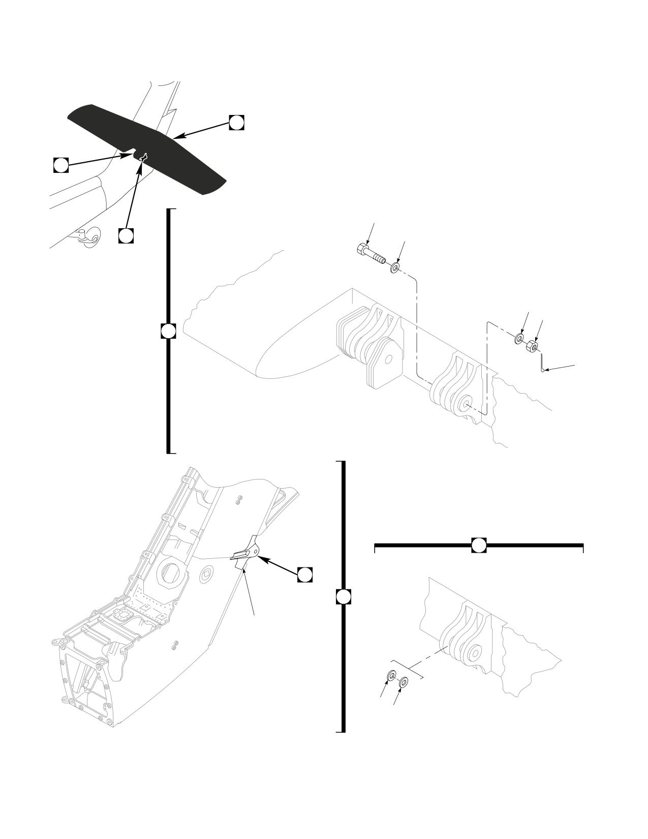
DMWR 1-1520-237
1
7
2
A
3
4
5
1
6
7
B
A
10
8
9
AB3105_1
SA
Figure E-25. Aft Spar Fitting Modification Kit (Sheet 1 of 2)
E-250
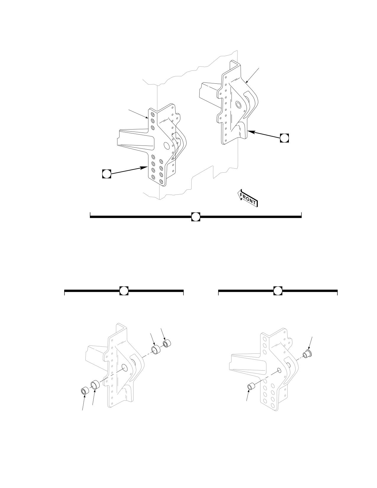
DMWR 1-1520-237
15
11
16
12
B
16
12
17
18
13
14
18
17
AB3105_2
SA
Figure E-25. Aft Spar Fitting Modification Kit (Sheet 2 of 2)
E-251
DMWR 1-1520-237
QTY
USABLE
FIGURE &
PER
ON
INDEX NO.
PART NUMBER
1 2 3 4 5 6 7
DESCRIPTION
ASSY
CODE
E-25-
70070-20588-011
AFT SPAR FITTING MODIFICATION KIT
REF
-1
70070-20588-014
M/K STAB INSTL
1
-2
NAS6210-48D
. BOLT
1
-3
MS20002C10
. WASHER
1
-4
MS20002-10
. WASHER
2
-5
MS17826-10
. NUT
1
-6
MS24665-374
. COTTER PIN
1
-7
70070-20588-015
. STAB INSTL, Modified from 70000-07050-011)...
REF
-8
70070-20588-101
. STEEL WASHER
1
-9
70070-20588-102
. GASKET WASHER
1
-10
70070-20588-045
SPAR ASSY, (Reidentified from 70202-06052-
041)
REF
*
70070-20588-046
SPAR ASSY, (Reidentified from 70202-06052-
043)
REF
*
70070-20588-047
SPAR ASSY, (Reidentified from 70202-06052-
044)
REF
*
70070-20588-048
SPAR ASSY, (Reidentified from 70202-06052-
045)
REF
*
-11
70070-20588-013
M/K FITTING ASSY
1
-12
70070-20588-043
. FITTING ASSY
REF
-13
FMI-718-45010-A
. BUSHING, (51439)
1
FMI-718-45110-A
. BUSHING, (51439)
1
*
FMI-718-45210-A
. BUSHING, (51439)
1
*
FMI-718-45310-A
. BUSHING, (51439)
1
*
FMI-718-45410-A
. BUSHING, (51439)
1
*
FMI-718-45510-A
. BUSHING, 5TH-OS, (51439)
1
*
-14
FMI-718-45030-A
. BUSHING, NOMINAL, (51439)
1
FMI-718-45130-A
. BUSHING, 1ST-OS, (51439)
1
*
FMI-718-45230-A
. BUSHING, 2ND-OS, (51439)
1
*
FMI-718-45330-A
. BUSHING, 3RD-OS, (51439)
1
*
FMI-718-45430-A
. BUSHING, 4TH-OS, (51439)
1
*
FMI-718-45530-A
. BUSHING, 5TH-OS, (51439)
1
*
-15
70070-20588-012
M/K FITTING ASSY
1
-16
70070-20588-041
. FITTING ASSY, (Reidentified from 70209-
06052-043)
REF
70070-20588-042
. FITTING ASSY, (Reidentified from 70209-
06052-046)
REF
70070-20588-044
. FITTING ASSY, (Reidentified from 70209-
06052-041)
REF
-17
KNDB 12-25
. SPHERICAL BEARING, (97613)
2
-18
FMI-718-45020-A
. BUSHING, (51439)
2
FMI-718-45120-A
. BUSHING, (51439)
2
*
FMI-718-45220-A
. BUSHING, (51439)
2
*
FMI-718-45320-A
. BUSHING, (51439)
2
*
FMI-718-45420-A
. BUSHING, (51439)
2
*
FMI-718-45520-A
. BUSHING, 5TH-OS, (51439)
2
*
FMI-718-45620-A
. BUSHING OS, (51439)
2
*
E-252
DMWR 1-1520-237
E-22. L/H R/H FIREWALL MODIFICATION KIT (50-19).
Subject: Left and Right Side Firewall Assemblies, Modification of, dated 31 March 2003
Purpose: Provide instructions to modify/reinforce existing firewall installation to prevent wear and fatigue cracking.
Model:
UH-60A
Description: The following is a brief overview of the work required to modify left and right side firewall assemblies. New
doublers, angles, straps, and spacers are installed to left and right firewall assemblies.
Drawings required for modification:
70070-30307, 70304-02114
References: (a) Special Service Instructions (SSI) No. 50-31, Installation of 9A to A9 Recapitalization Program, dated
March 31, 2003
Instructions:
NOTE
• A complete review of this SSI is recommended before modifying right and left side firewall assemblies.
• Before beginning this modification procedure, use the material information list to inventory the kit. Make
sure all parts are present and in serviceable condition.
• Where drawing numbers are not listed within individual steps, drawing(s) listed in preceding step(s) are
the controlling authority.
• The sheet metal and structural modifications in this SSI shall be done by personnel experienced in reading
modification drawings. Routine steps such as cleaning, layout and drilling, deburring, standard repairs,
corrosion control, clean up after rework, chemical coating for aluminum after cutting/trimming parts, paint
touch up, and safety practices may not be called out herein. However, these steps and all other required
routine tasks shall be done.
• Slight variations to the instructions contained herein are allowed, as long as the intent of the modification
is accomplished.
A.
Preparation for modification and removal of equipment:
(1)
Confirm that all warnings, cautions, and notes are complied with per reference (a).
(2)
The helicopter is prepared for modification per reference (a).
B.
Modification of left side firewall as follows (Dwg 70070-30307):
(1)
Remove and discard angle (70304-02115-117) from left side firewall assembly (Sheet 3, Zone 7-B).
(2)
Remove and save for reinstallation angle (70304-02115-118) (Sheet 3, Zone 6-E).
(3)
Install doubler (70070-30307-101) at station 349.00, left buttline 21.25 using fasteners shown (Sheet 3,
Zone 14-B).
E-253
DMWR 1-1520-237
(4)
Install angle (70070-30275-103), spacer (70070-30275-104), and angle (removed in step B.(2)) (70304-
02115-118) using fasteners shown (Sheet 3, Zones 7-B, 5-D, and 6-E).
(5)
Install strap (70070-30307-102) at station 355.00, left buttline 20.00 using fasteners shown (Sheet 3, Zone
11-D).
C.
Modification of right side firewall as follows (Dwg’s 70070-30307, and 70304-02114):
(1)
Remove and save for reinstallation bracket assembly (70551-01101-041) and bracket (AN743C13) (Dwg
70070-30307, Sheet 3, Zones 14-H and 14-F).
(2)
Remove two doublers (70304-02114-133) and angles (70304-02114-116, -119 and -157) from right side
firewall (Dwg 70304-02114, Sheet 1, Zones 16-L, 17-M, 14-K and 17-L).
(3)
Install doubler (70070-30307-103), bracket assembly (removed in step C.(1)) (70551-01101-041), angles
(70304-02114-167, -168 and -170), two doublers (70304-02114-169) and bracket (AN743C13) using fasteners
shown (Dwg 70070-30307, Sheet 3, Zones 14-G, 13-H and 14-F; Dwg 70304-02114, Sheet 1, Zones 17-N, 14-L and
17-L).
(4)
Install strap (70070-30307-104) using fasteners shown (Dwg 70070-30307, Sheet 3, Zone 11-F).
(5)
After rework reidentify firewall assemblies with pen and contrasting ink as follows:
FROM
TO
70304-02115-041
70070-30307-041
70304-02115-045
70070-30307-042
70304-02115-047
70070-30307-043
70304-02115-049
70070-30307-044
70304-02115-053
70070-30307-045
70304-02114-041
70070-30307-046
70304-02114-043
70070-30307-047
70304-02114-045
70070-30307-048
70304-02114-046
70070-30307-049
70304-02115-052
70070-30307-055
70304-02115-048
70070-30307-054
70304-02115-044
70070-30307-053
70304-02115-043
70070-30307-052
70304-02114-049
70070-30307-050
70304-02114-051
70070-30307-051
D.
Reinstallation of removed equipment:
(1)
Reinstall removed equipment per reference (a).
E.
Record of Compliance:
(1)
Make an appropriate logbook entry to show compliance with this Special Service Instruction.
E-254
DMWR 1-1520-237
Weight and Balance Data:
POUNDS
INCHES AFT
MOMENT/
QTY
PART NO.
NOMENCLATURE
WEIGHT
OF DATUM
1000
1
70070-30307-011
Mod. Kit, Firewall
1
70070-30307-012
Mod. Kit, Firewall
Total:
+1.1
350.8
0.386
Weight and Balance: Change resulting from these instructions are as follows:
Change in basic weight:
+1.1 pounds
Moment arm:
350.8 in.
Change in basic moment/1000:
0.386
Manpower (Estimated)
No. of Personel
No. of Hours
Man-hours
Sheet Metal Mec
1
28.0
*28.0
*Does not include time required to prepare helicopter or return it to flight status.
Material Information:
A.
Modification Kit Required:
(1)
Kit A:
Qty
Nomenclature
Part Number
Source
1
Mod. Kit, Firewall LH,
70070-30307-011
(1)
consisting of:
70
Rivet
MS20615-4M5
1
Doubler
70070-30307-101
1
Strap
70070-30307-102
1
Angle
70070-30275-103
1
Spacer
70070-30275-104
(2)
Kit B:
Qty
Nomenclature
Part Number
Source
1
Mod. Kit, Firewall RH,
70070-30307-012
(1)
E-255
DMWR 1-1520-237
Qty
Nomenclature
Part Number
Source
consisting of:
71
Rivet
MS20615-4M5
4
Nutplate
MS21060-3
3
Nutplate
MS21062-3
1
Nutplate
MS21074-L3
18
Rivet
NAS1097AD3-9
1
Doubler
70070-30307-103
1
Strap
70070-30307-104
1
Angle
70304-02114-167
1
Angle
70304-02114-168
2
Doubler
70304-02114-169
1
Angle
70304-02114-170
B.
Source:
(1)
Available through normal supply channels
E-256
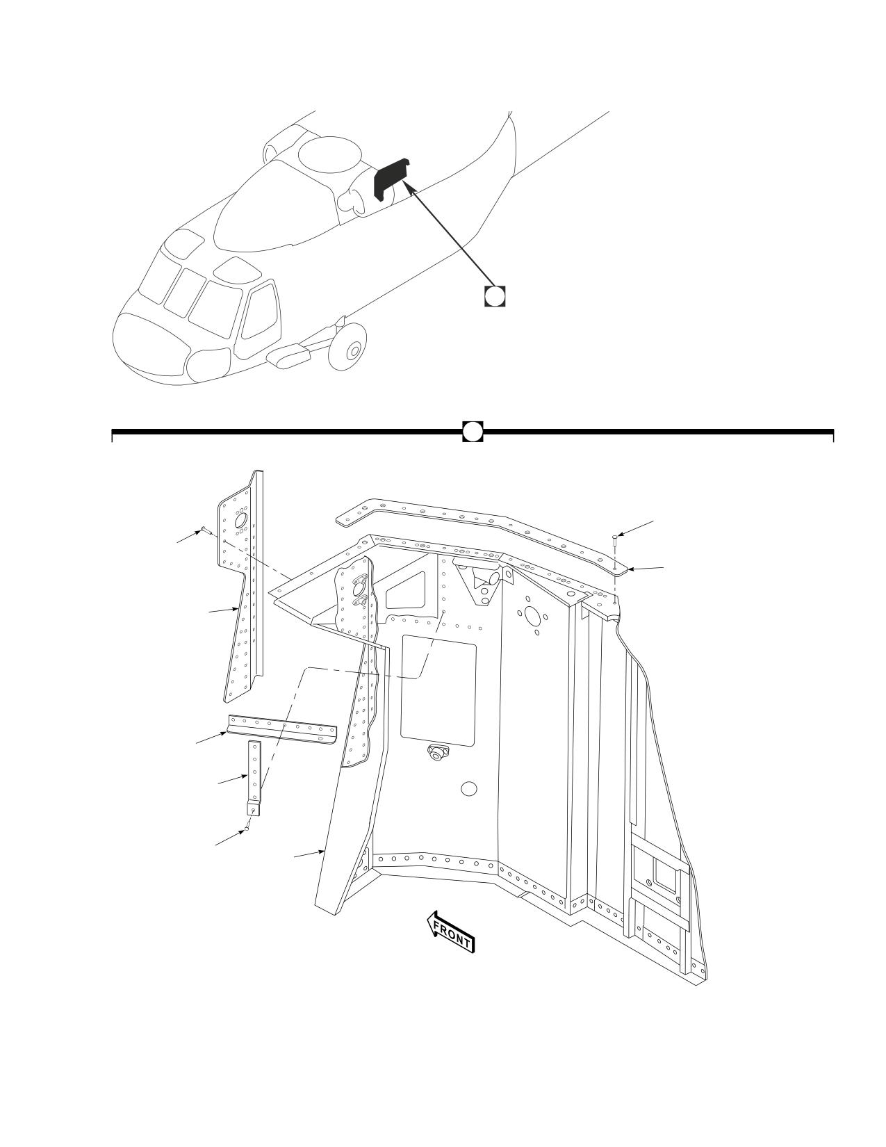
DMWR 1-1520-237
A
A
1
1
2
5
4
3
1
6
AB3085
SA
Figure E-26. L/H Firewall Modification Kit
E-257
DMWR 1-1520-237
QTY
USABLE
FIGURE &
PER
ON
INDEX NO.
PART NUMBER
1 2 3 4 5 6 7
DESCRIPTION
ASSY
CODE
E-26-
70070-30307-011
L/H FIREWALL MODIFICATION KIT
REF
-1
MS20615-4M5
. RIVET
70
-2
70070-30275-102
. STRAP
1
-3
70070-30275-104
. SPACER
1
-4
70070-30307-103
. ANGLE
1
-5
70070-30307-101
. DOUBLER
1
-6
70070-30307-013
. FIREWALL INSTL (Reidentified from 70304-
02200-011)
REF
70070-30307-041
. FIREWALL ASSY (Reidentified from 70304-
02115-041)
REF
70070-30307-042
. FIREWALL ASSY (Reidentified from 70304-
02115-045)
REF
70070-30307-043
. FIREWALL ASSY (Reidentified from 70304-
02115-047)
REF
70070-30307-044
. FIREWALL ASSY (Reidentified from 70304-
02115-049)
REF
70070-30307-045
. FIREWALL ASSY (Reidentified from 70304-
02115-053)
REF
70070-30307-052
. FIREWALL ASSY (Reidentified from 70304-
02115-043)
REF
70070-30307-053
. FIREWALL ASSY (Reidentified from 70304-
02115-044)
REF
70070-30307-054
. FIREWALL ASSY (Reidentified from 70304-
02115-048)
REF
70070-30307-055
. FIREWALL ASSY (Reidentified from 70304-
02115-052)
REF
E-258
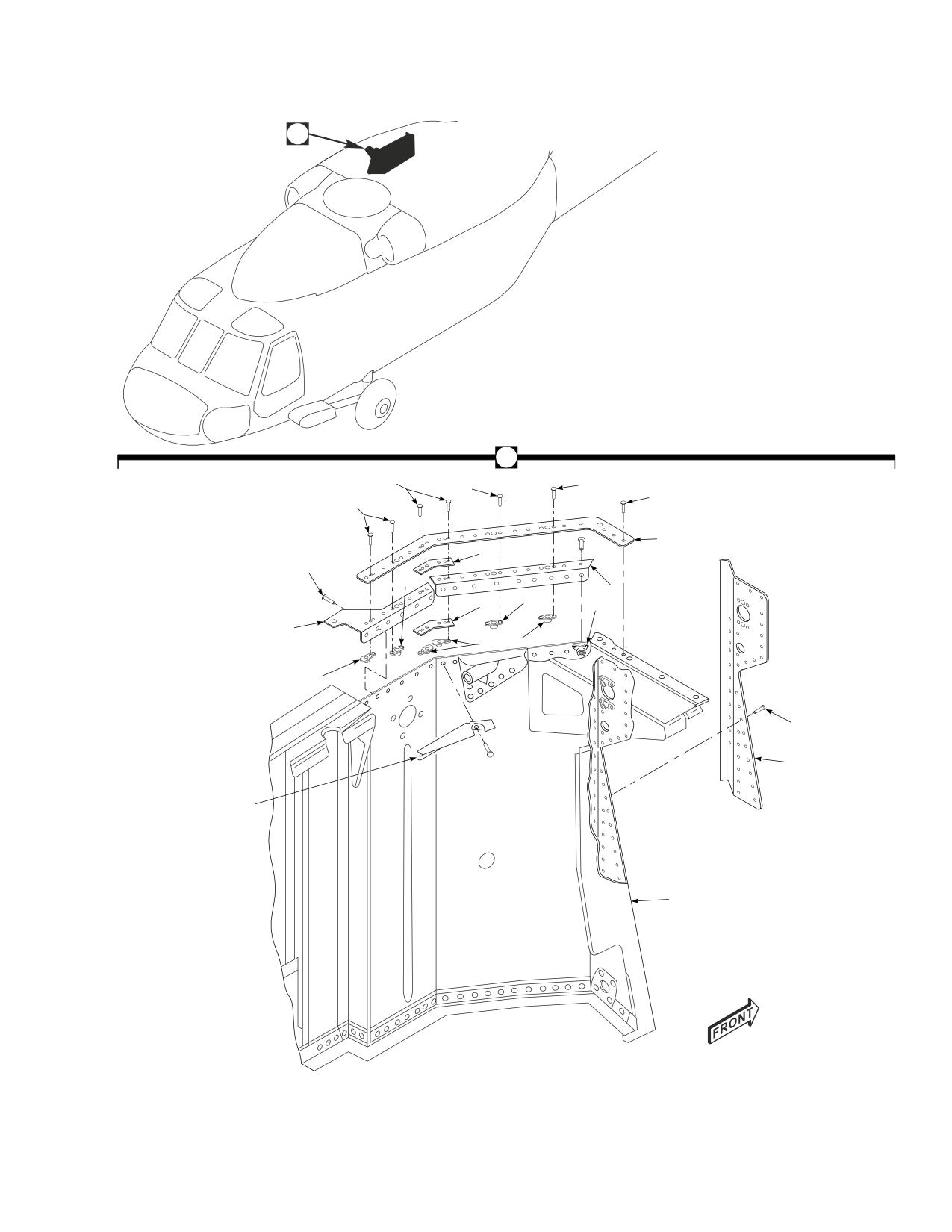
DMWR 1-1520-237
A
A
1
1
1
4
1
5
9
4
2
8
2
9
6
7
3
2
3
4
10
11
12
AB3086
SA
Figure E-27. R/H Firewall Modification Kit
E-259
DMWR 1-1520-237
QTY
USABLE
FIGURE &
PER
ON
INDEX NO.
PART NUMBER
1 2 3 4 5 6 7
DESCRIPTION
ASSY
CODE
E-27-
70070-30307-012
R/H FIREWALL MODIFICATION KIT
REF
-1
NAS1097AD3-9
. RIVET
18
-2
MS21060-3
. NUTPLATE
4
-3
MS21062-3
. NUTPLATE
3
-4
MS20615-4M5
. RIVET
71
-5
70070-30307-104
. STRAP
1
-6
MS21074-L3
. NUTPLATE
1
-7
70304-02114-167
. ANGLE
1
-8
70304-02114-168
. ANGLE
1
-9
70304-02114-169
. DOUBLER
2
-10
70070-30307-103
. DOUBLER
1
-11
70304-02114-170
. ANGLE
1
-12
70070-30307-014
. FIREWALL INSTL (Reidentified from 70304-
02200-012)
REF
70070-30307-046
. FIREWALL ASSY (Reidentified from 70304-
02114-041)
REF
70070-30307-047
. FIREWALL ASSY (Reidentified from 70304-
02114-043)
REF
70070-30307-048
. FIREWALL ASSY (Reidentified from 70304-
02114-045)
REF
70070-30307-049
. FIREWALL ASSY (Reidentified from 70304-
02114-046)
REF
70070-30307-050
. FIREWALL ASSY (Reidentified from 70304-
02114-049)
REF
70070-30307-051
. FIREWALL ASSY (Reidentified from 70304-
02114-051)
REF
E-260
DMWR 1-1520-237
E-23. COWL ASSEMBLY MODIFICATION KIT (50-33).
Subject: Engine Cowl Assembly, Left and Right Side, Modification of, dated 31 March 2003
Purpose: Provide instructions for installation of splice straps on engine cowl assembly.
Model:
UH-60A
Description: New one piece hinge fitting assemblies are installed to reinforce the hinge area.
Drawings Required for Modification:
70070-30308
References: (a) Special Service Instructions (SSI) No. 50-31, Installation of 9A to A9 Recapitalization Program, dated
March 31, 2003
Instructions:
NOTE
• A complete review of this SSI is recommended before incorporating the engine cowl assembly modification
kit.
• Before beginning this modification procedure, use the material information list to inventory the kit. Make
sure all parts are present and in serviceable condition.
• Slight variations to the instructions contained herein are allowed, as long as the intent of the modification
is accomplished.
• The sheet metal and structural modifications in this SSI shall be done by personnel experienced in sheet
metal/structural work, skilled in reading modification drawings, standard working/repair, and safety
practices. Routine steps such as cleaning, layout and drilling, deburring, standard repairs, corrosion
control, clean up after rework, chemical coating for aluminum after cutting/trimming parts, and paint
touch up may not be called out herein. However, these steps and all other required routine tasks shall be
done.
• Where drawing numbers are not listed within individual steps, drawing(s) listed in preceding step(s) are
the controlling authority.
• When installing fasteners refer to drawing sheet and zones for rivet code on applicable drawings.
A.
Preparation for modification:
(1)
Confirm all warnings, cautions, and notes are complied with per reference (a).
(2)
Perform preparation for modification per reference (a).
B.
Installation of parts for modification of engine cowl assembly:
NOTE
• Drawing shows right side foward hinge only. Rework of remaining hinge locations is the same, except
remove hinge -042, and install hinge fitting assembly -048.
E-261
DMWR 1-1520-237
• This modification does not apply to platforms with alternate method of manufacturing with walking
surfaces intergral with rib support.
(1)
Position cowl assembly (70302-02141-041, -042, -044, -045, -048, or -049) on suitable work bench.
(2)
Remove hinge (70302-02157-041 and -042) and shims (70302-02141-109) if applicable, from forward
and aft ribs as follows:
(a)
Remove and discard seven screws, nuts, and washers on hinge assembly (70302-02157-041 and -042)
(Dwg 70070-30308, Sheet 2, Zone 6-E).
NOTE
If shims (70302-02141-109) are installed proceed to step B.(2)(b). Otherwise proceed to step B.(2).
(b)
Wedge a non-metalic scraper in between the shims of aluminum stock (70302-02141-109) and remove
and save for reinstallation (Sheet 2, Zone 5-C and Note 12).
(c)
Position and pin at two locations removed hinge (70302-02141-041 or -042) on top of new hinge fitting
assembly (70070-30308-047 or -048).
NOTE
Placing a spacer bar in between the old and new hinge assemblies will insure proper alignment during
pinning and drilling operation.
(d)
Transfer drill from old hinge (70302-02141-041 or -042) into new hinge fitting assembly (70070-30308-
047 or -048) at two locations.
(e)
Remove pins and clean and deburr the two holes drilled in step (d).
(f)
Position hinge fitting assembly (70070-30308-047 or -048) into engine cowling (70302-02141-041,
-042, -044,-045, -048, or -049) and pin two previously drilled holes (Sheet 2, Zone 6-E).
(g)
Transfer drill remaining five 0.1935-inch diameter holes from engine cowl (70302-02141-042, -044,
-045, -048, or -049) to hinge fitting assembly (70070-30308-047, or -048) to match existing hole locations (Sheet 2,
Zone 7-C).
(h)
Temporarily fasten all holes in hinge fitting (70070-30308-047 or -048) to engine cowl assembly (70302-
02141-041, -042, -044, -045, -048, or -049) (Sheet 2, Zone 7-C).
(i)
Layout 14 holes in engine cowl assembly (70070-30308-041, -042, -044, -045, -045, -048, or -049)
and hinge fitting assembly (70070-30308-047 or -048) (Sheet 2, Zone 8-G).
(j)
Remove hinge ftting assembly (70070-30308-047 or -048) deburr and touch up as required.
(k)
Install hinge fitting assembly (70070-30308-047 or -048) into cowl assembly (70302-02141-041, -042,
-044, -045, -048, or -049) using hardware shown. If shims were previously removed, reinstall at this time (Sheet 2, Zone
8-C).
E-262
DMWR 1-1520-237
WARNING
OBSERVE ALL CAUTIONS AND WARNINGS ON CONTAINERS WHEN USING CONSUMABLES.
WHEN APPLICABLE, WEAR NECESSARY PROTECTIVE GEAR DURING HANDLING AND USE. IF A
CONSUMABLE IS FLAMMABLE OR EXPLOSIVE, MAKE CERTAIN CONSUMABLE AND ITS VAPORS ARE
KEPT AWAY FROM HEAT, SPARK, AND FLAME. MAKE CERTAIN EQUIPMENT IS PROPERLY
GROUNDED AND FIREFIGHTING EQUIPMENT IS READILY AVAILABLE PRIOR TO USE. FOR AD-
DITIONAL INFORMATION ON TOXICITY, FLASHPOINT, AND FLAMMABILITY OF CHEMICALS,
CONSULT YOUR MEDICAL PEOPLE, OR MANUFACTURER OF THE CONSUMABLE.
(l)
Mix syntactic foam (Epocast, Type II, 1652 A/B) per manufacturers instructions and fill interior of the ribs
through previously drilled holes in step B.(2)(i) (Sheet 2, Zone 5-G).
(m)
Drill out holes previously filled with syntactic foam (Epocast, Type II, 1652 A/B) and install fasteners
shown (Sheet 2, Zone 8-G).
(3)
After rework reidentify engine cowl assembly using pen and contrasting ink as follows:
FROM
TO
70302-02141-041
70070-30308-041
70302-02141-042
70070-30308-042
70302-02141-044
70070-30308-043
70302-02141-045
70070-30308-044
70302-02141-048
70070-30308-045
70302-02141-049
70070-30308-046
C.
Reinstallation of removed equipment:
(1)
Perform installation of parts and equipment per reference (a).
D.
Record of Compliance:
(1)
Make an appropriate logbook entry to show compliance with this Special Service Instruction.
Weight and Balance Data:
POUNDS
INCHES AFT
MOMENT/
QTY
PART NO.
NOMENCLATURE
WEIGHT
OF DATUM
1000
1
70070-30308-011
Mod. Kit
+3.0
375.5
+1.126
Weight and Balance: Change resulting from these instructions are as follows:
Change in basic weight:
+3.0 pounds
Moment arm:
375.5 in.
E-263
DMWR 1-1520-237
Change in basic moment/1000:
1.126
Manpower (Estimated)
No. of Personel
No. of Hours
Man-hours
Sheet Metal Mechanic
1
32.0
*32.0
*Does not include time required to prepare helicopter or return it to flight status.
Material Information:
A.
Modification Kit Required:
Qty
Nomenclature
Part Number
Source
1
Mod. Kit, Cowl Assembly-Engine
70070-30308-011
(1)
consisting of:
2
Hinge Fitting Assembly
70070-30308-047
2
Hinge Fitting Assembly
70070-30308-048
75
Pin, Hi Lok
HL20PB-6-10
75
Collar
HL75-6AW
31
Screw
MS27039C1-14
31
Nut
MS21043-3
62
Washer
NAS1149C0332R
B.
Consumable Material:
WARNING
OBSERVE ALL CAUTIONS AND WARNINGS ON CONTAINERS WHEN USING CONSUMABLES.
WHEN APPLICABLE, WEAR NECESSARY PROTECTIVE GEAR DURING HANDLING AND USE. IF A
CONSUMABLE IS FLAMMABLE OR EXPLOSIVE, MAKE CERTAIN CONSUMABLE AND ITS VAPORS ARE
KEPT AWAY FROM HEAT, SPARK, AND FLAME. MAKE CERTAIN EQUIPMENT IS PROPERLY
GROUNDED AND FIREFIGHTING EQUIPMENT IS READILY AVAILABLE PRIOR TO USE. FOR AD-
DITIONAL INFORMATION ON TOXICITY, FLASHPOINT, AND FLAMMABILITY OF CHEMICALS,
CONSULT YOUR MEDICAL PEOPLE, OR MANUFACTURER OF THE CONSUMABLE.
Qty
Nomenclature
Part Number
Source
16 oz.
Foam, Syntactic
Epocast, Type II, 1652 A/B,
(1)
SS9587-003 or equivalent
C.
Source:
(1)
Available through normal supply channels
E-264
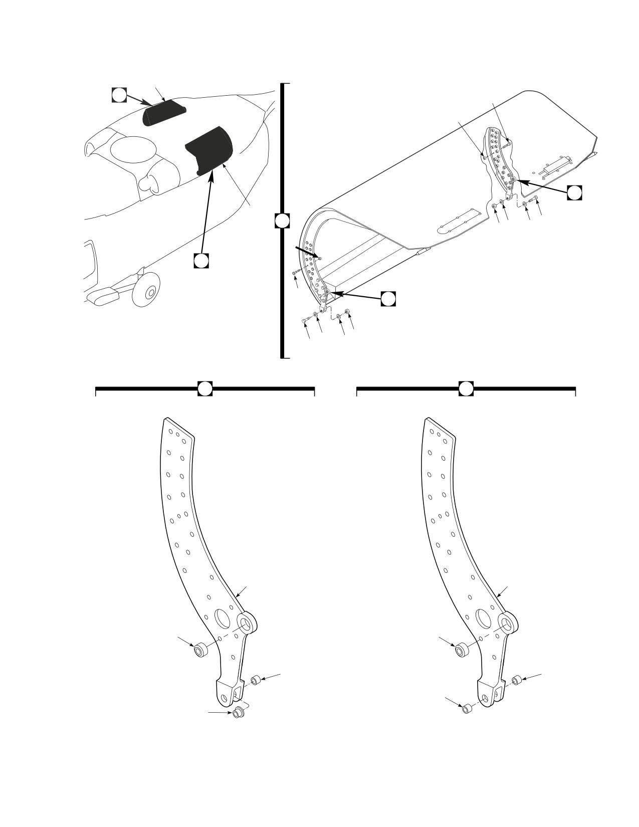
DMWR 1-1520-237
1
2
3
4
12
1
2
5
7
6
6
4
2
3
8
7
6
6
5
12
8
16
11
13
9
15
10
10
14
AB3089
SA
Figure E-28. Cowl Assembly Modification Kit
E-265
DMWR 1-1520-237
QTY
USABLE
FIGURE &
PER
ON
INDEX NO.
PART NUMBER
1 2 3 4 5 6 7
DESCRIPTION
ASSY
CODE
E-28-
70070-30308-011
COWL ASSEMBLY MODIFICATION KIT
REF
-1
70070-30308-013
. COWL INSTALLATION, (Modifies 70302-02200-
011)
REF
-2
70070-30308-041
. COWL ASSY (Reidentified from 70302-02141-
041)
REF
70070-30308-042
. COWL ASSY (Reidentified from 70302-02141-
042)
REF
70070-30308-043
. COWL ASSY (Reidentified from 70302-02141-
044)
REF
70070-30308-044
. COWL ASSY (Reidentified from 70302-02141-
045)
REF
70070-30308-045
. COWL ASSY (Reidentified from 70302-02141-
048)
REF
70070-30308-046
. COWL ASSY (Reidentified from 70302-02141-
049)
REF
-3
HL20PB-6-10
. HI-LOK PIN, (73197)
14
-4
HL75-6AW
. COLLAR, (73197)
14
-5
MS27039C1-14
. SCREW
28
-6
NAS1149C0332R
. FLAT WASHER
56
-7
MS21043-3
. NUT
28
-8
70070-30308-047
. HINGE FITTING ASSEMBLY
2
-9
MS14103-4K
. . BEARING
1
SBSH8ATC20ZM
. . BEARING
1
*
-10
NAS537-4-034
. . BUSHING
2
-11
70070-30308-102
. . HINGE FITTING
1
-12
70070-30308-048
. HINGE FITTING ASSEMBLY
2
-13
MS14103-4K
. . BEARING
1
SBSH8ATC20ZM
. . BEARING
1
*
-14
NAS77-4-020
. . BEARING
1
-15
NAS75-4-011
. . BUSHING
1
-16
70070-30308-102
. . HINGE FITTING
1
E-266
DMWR 1-1520-237
E-24. HIRSS REPAIR KIT (50-30).
Subject: HIRSS Repair Kit ; Installation of
Purpose: Provide instructions to install HIRSS repair kit.
Model:
UH-60A
Description The following is a brief overview of the work required to install the HIRSS repair kit. New doublers, fillers,
angles, and radius blocks are installed to the left and right exhaust extenders.
Drawings required for modification:
70072-30000, 70308-03611
References: (a) Special Service Instructions (SSI) No. 50-31, Installation of 9A to A9 Recapitalization Program, dated
March 31, 2003
Instructions:
NOTE
• A complete review of this SSI is recommended before installing HIRSS repair kit.
• Before beginning this modification procedure, use the material information list to inventory the kit. Make
sure all parts are present and in serviceable condition.
• Where drawing numbers are not listed within individual steps, drawing(s) listed in preceding step(s) are
the controlling authority.
• The sheet metal and structural modifications in this SSI shall be done by personnel experienced in reading
modification drawings. Routine steps such as cleaning, layout and drilling, deburring, standard repairs,
corrosion control, clean up after rework, chemical coating for aluminum after cutting/trimming parts, paint
touch up, and safety practices may not be called out herein. However, these steps and all other required
routine tasks shall be done.
• When installing fasteners refer to drawing sheet and zones and rivet code on applicable drawing.
• Slight variations to the instructions contained herein are allowed, as long as the intent of the modification
is accomplished.
A.
Preparation for modification and removal of equipment.
(1)
Confirm that all warnings, cautions, and notes are complied with per reference (a).
(2)
Perform preparation for modification per reference (a).
B.
Modification of left and right exhaust extender assemblies as follows (Dwg 70308-03611):
(1)
Remove support angle (70308-03611-124) from right side exhaust extender (Sheet 2, Zone 21-D).
(2)
Temporarily install new support angle (70308-03611-124), angle clip (70308-03611-159), filler plate
(70308-03611-160), and radius block (SS1058-5-38-24) (Sheet 2, Zones 21-D, 22-B, and 24-H; Sheet 6, Zone 21-C).
E-267
DMWR 1-1520-237
(3)
Position and temporarily install doubler (70308-03611-166) and fillers (70308-03611-167 and 168) (Sheet
2, Zones 18-H, 20-G, and 18-F).
(4)
Remove all parts temporarily installed in steps B.(2) and B.(3), deburr and touch up as required.
(5)
Install all parts removed in step B.(4) using fasteners shown (Sheet 2, Zones 21-D, 22-B, 24-H, 18-H, 20-G,
and 18-F; Sheet 6, Zone 21-C; Sheet 1, Note 20).
(6)
Remove support angle (70308-03611-123) from left side exhaust extender (Sheet 2, Zone 21-D).
(7)
Temporarily install new support angle (70308-03611-123), angle clip (70308-03611-159), filler plate
(70308-03611-160), and radius block (SS1058-5-38-24) (Sheet 2, Zones 21-D, 22-B, and 24-H; Sheet 6 Zone 21-C).
(8)
Position and temporarily install doubler (70308-03611-165) and fillers (70308-03611-167 and -168)
(Sheet 2, Zones 18-H, 20-G, and 18-F).
(9)
Remove fitted parts, deburr and touch up as required.
(10)
Install fitted parts using fasteners shown (Sheet 2, Zones 21-D, 22-B, 24-H, 18-H, 20-G, and 18-F; Sheet 6,
Zone 21-C; Sheet 1, Note 20).
C.
Reinstallation of removed equipment:
(1)
Install removed equipment per reference (a).
D.
Record of Compliance:
(1)
Make an appropriate logbook entry to show compliance with this Special Service Instruction.
Weight and Balance Data:
POUNDS
INCHES AFT
MOMENT/
QTY
PART NO.
NOMENCLATURE
WEIGHT
OF DATUM
1000
1
70072-3000-011
Mod. Kit, HIRSS Repair Kit
+2.1
442.2
0.929
Weight and Balance: Change resulting from these instructions are as follows:
Change in basic weight:
+ 2.1 pounds
Moment arm:
442.2 in.
Change in basic moment/1000:
0.929
E-268
DMWR 1-1520-237
Manpower (Estimated)
No. of Personel
No. of Hours
Man-hours
Sheet Metal Mechanic
1
16.0
*16.0
*Does not include time required to prepare helicopter or return it to flight status.
Material Information:
A.
Modification Kit Required:
Qty
Nomenclature
Part Number
Source
1
Mod. Kit, HIRSS Repair Kit,
70072-30000-011
(1)
consisting of:
1
Repair Kit, RH,
70072-30000-012
consisting of:
2
Collar
HL1087ATW-5
2
Pin, Hi Lok
HL20PB-5-2
11
Rivet, Blind
NAS1738M4-2
15
Rivet, Blind
NAS1738M4-3
8
Rivet, Blind
NAS1738M4-4
41
Rivet, Blind
NAS1738M4-5
1
Radius Block
SS1058-5-38-24
1
Support Angle
70308-03611-124
1
Angle Clip
70308-03611-159
1
Filler Plate
70308-03611-160
1
Doubler
70308-03611-166
1
Filler
70308-03611-167
2
Filler
70308-03611-168
1
Repair Kit, LH,
70072-30000-013
consisting of:
2
Collar
HL1087ATW-5
2
Pin, Hi Lok
HL20PB-5-2
11
Rivet, Blind
NAS1738M4-2
15
Rivet, Blind
NAS1738M4-3
8
Rivet, Blind
NAS1738M4-4
41
Rivet, Blind
NAS1738M4-5
1
Radius Block
SS1058-5-38-24
1
Support Angle
70308-03611-123
1
Angle Clip
70308-03611-159
1
Filler Plate
70308-03611-160
1
Doubler
70308-03611-165
1
Filler
70308-03611-167
E-269
DMWR 1-1520-237
Qty
Nomenclature
Part Number
Source
2
Filler
70308-03611-168
B.
Consumable Material:
WARNING
OBSERVE ALL CAUTIONS AND WARNINGS ON CONTAINERS WHEN USING CONSUMABLES.
WHEN APPLICABLE, WEAR NECESSARY PROTECTIVE GEAR DURING HANDLING AND USE. IF A
CONSUMABLE IS FLAMMABLE OR EXPLOSIVE, MAKE CERTAIN CONSUMABLE AND ITS VAPORS ARE
KEPT AWAY FROM HEAT, SPARK, AND FLAME. MAKE CERTAIN EQUIPMENT IS PROPERLY
GROUNDED AND FIREFIGHTING EQUIPMENT IS READILY AVAILABLE PRIOR TO USE. FOR AD-
DITIONAL INFORMATION ON TOXICITY, FLASHPOINT, AND FLAMMABILITY OF CHEMICALS,
CONSULT YOUR MEDICAL PEOPLE, OR MANUFACTURER OF THE CONSUMABLE.
Qty
Nomenclature
Part Number
Source
6 oz.
Sealant
RTV133 or equivalent
(1)
C.
Source:
(1)
Available through normal supply channels
E-270
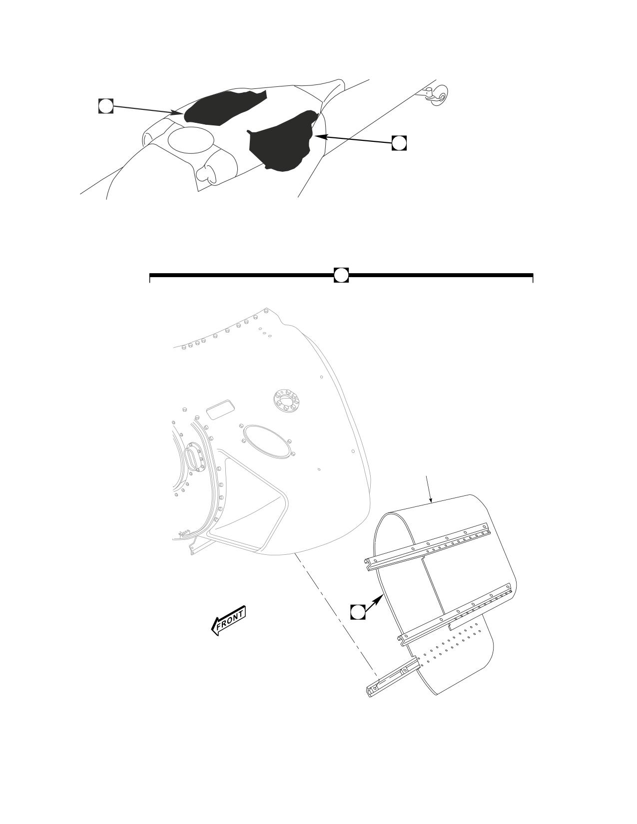
DMWR 1-1520-237
1
1
1
2
3
AB3087_1
SA
Figure E-29. HIRSS Repair Kit (Sheet 1 of 2)
E-271

DMWR 1-1520-237
3
16
8
9
15
7
10
12
14
4
5
11
6
13
AB3087_2
SA
Figure E-29. HIRSS Repair Kit (Sheet 2 of 2)
E-272
DMWR 1-1520-237
QTY
USABLE
FIGURE &
PER
ON
INDEX NO.
PART NUMBER
1 2 3 4 5 6 7
DESCRIPTION
ASSY
CODE
E-29-
70072-30000-011
HIRSS REPAIR KIT
REF
-1
70308-03611-011
. EXTENDER INSTALLATION
REF
70308-03611-012
. EXTENDER INSTALLATION
REF
70308-03611-013
. EXTENDER INSTALLATION
REF
70308-03611-014
. EXTENDER INSTALLATION
REF
-2
70308-03611-041
. EXTENDER ASSY. (Used on
70308-03611-011)
REF
70308-03611-042
. EXTENDER ASSY. (Used on
70308-03611-012)
REF
70308-03611-053
. EXTENDER ASSY. (Used on
70308-03611-013)
REF
70308-03611-054
. EXTENDER ASSY. (Used on
70308-03611-014)
REF
-3
70072-30000-013
. REPAIR KIT LH
1
70072-30000-012
. REPAIR KIT
1
-4
HL20PB-5-2
. . HI-LOK PIN, (73197)
2
-5
HL1087ATW-5
. . COLLAR, (73197)
2
-6
NAS1739M4-3
. . BLIND RIVET
2
-7
70308-03611-159
. . ANGLE CLIP
1
-8
NAS1738M4-2
. . BLIND RIVET
11
-9
NAS1738M4-3
. . BLIND RIVET
15
-10
NAS1738M4-4
. . BLIND RIVET
8
NAS1738M4-5
. . BLIND RIVET
41
*
-11
70308-03611-165
. . DOUBLER, (Used on 70308-03611-041 and
-053)
1
70308-03611-166
. . DOUBLER, (Used on 70308-03611-042 and
-054)
1
-12
70308-03611-167
. . FILLER
1
-13
70308-03611-168
. . FILLER
2
-14
SS1058-5-38-24
. . RADIUS BLOCK
1
-15
70308-03611-123
. . SUPPORT ANGLE, (Used on 70308-03611-041
and -053)
1
70308-03611-124
. . SUPPORT ANGLE, (Used on 70308-03611-042
and -054)
1
-16
70308-03611-160
. . FILLER PLATE
1
E-273/(E-274 blank)
DMWR 1-1520-237-3
FOR THE COMMANDER:
JOHN B. SMITH
Colonel, QM
Chief of Staff
OFFICIAL:
RICHARD E. TURNER
Deputy Director
Integrated Materiel Management Center
These are the instructions for sending an electronic 2028
The following format must be used if submitting an electronic 2028. The subject line must be
exactly the same and all fields must be included; however only the following fields are
mandatory: 1, 3, 4, 5, 6, 7, 8, 9, 10, 13, 15, 16, 17, and 27.
From:
“Whomever” <whomever@wherever.army.mil>
To:
2028@redstone.army.mil
Subject: DA Form 2028
1. From: Joe Smith
2. Unit: home
3. Address: 4300 Park
4. City: Hometown
5. St: MO
6. Zip: 77777
7. Date Sent: 19--OCT--93
8. Pub no: 55--2840--229--23
9. Pub Title: TM
10. Publication Date: 04--JUL--85
11. Change Number: 7
12. Submitter Rank: MSG
13. Submitter FName: Joe
14. Submitter MName: T
15. Submitter LName: Smith
16. Submitter Phone: 123--123--1234
17. Problem: 1
18. Page: 2
19. Paragraph: 3
20. Line:
4
21. NSN: 5
22. Reference: 6
23. Figure:
7
24. Table: 8
25. Item: 9
26. Total:
123
27. Text:
This is the text for the problem below line 27.
Use Part II (reverse) for Repair Parts and Spe-
DATE
RECOMMENDED CHANGES TO PUBLICATIONS AND
cial Tool Lists (RPSTL) and Supply Catalogs/
Supply Manuals (SC/SM)
BLANK FORMS
For use of this form, see AR 25--30; the proponent agency is ODISC4.
8/30/02
TO: (Forward to proponent of publication or form)(Include ZIP Code)
FROM: (Activity and location)(Include ZIP Code)
Commander, U.S. Army Aviation and Missile Command
MSG, Jane Q. Doe
ATTN: AMSAM--MMC--MA--NP
1234 Any Street
R eds t one A r s enal, AL 35898
Nowhere Town, AL 34565
PART 1 -- ALL PUBLICATIONS (EXCEPT RPSTL AND SC/SM) AND BLANK FORMS
PUBLICATION/FORM NUMBER
DATE
TITLE Organizational, Direct Support, And General
TM 9--1005--433--24
16 Sep 2002SupportMaintenanceManualforMachineGun,.50CaliberM3PandM3PMachineGunElectricalTestSet
Used On Avenger Air Defense Weapon System
ITEM
PAGE
PARA--
LINE
FIGURE
TABLE
RECOMMENDED CHANGES AND REASON
NO.
NO.
GRAPH
NO. *
NO.
NO.
1
WP0005
2
Test or Corrective Action column should identify a different WP number.
PG 3
* Reference to line numbers within the paragraph or subparagraph.
TYPED NAME, GRADE OR TITLE
TELEPHONE EXCHANGE/
SIGNATURE
AUTOVON, PLUS EXTEN-
SION
MSG, Jane Q. Doe, SFC
788--1234
DA FORM 2028, FEB 74
REPLACES DA FORM 2028, 1 DEC 68, WHICH WILL BE USED.
USAPA V3.01
TO: (Forward direct to addressee listed in publication)
FROM: (Activity and location) (Include ZIP Code)
DATE
Commander, U.S. Army Aviation and Missile Command
MSG, Jane Q. Doe
8/30/02
ATTN: AMSAM--MMC--MA--NP
1234 Any Street
R eds t one A r s enal, AL 35898
Nowhere Town, AL 34565
PART II -- REPAIR PARTS AND SPECIAL TOOL LISTS AND SUPPLY CATALOGS/SUPPLY MANUALS
PUBLICATION NUMBER
DATE
TITLE
TOTAL NO.
PAGE
COLM
LINE
NATIONAL STOCK
REFERENCE
FIGURE
ITEM
OF MAJOR
RECOMMENDED ACTION
NO.
NO.
NO.
NUMBER
NO.
NO.
NO.
ITEMS
SUPPORTED
PART III -- REMARKS (Any general remarks or recommendations, or suggestions for improvement of publications and
blank forms. Additional blank sheets may be used if more space is needed.)
TYPED NAME, GRADE OR TITLE
TELEPHONE EXCHANGE/AUTOVON,
SIGNATURE
PLUS EXTENSION
MSG, Jane Q. Doe, SFC
788--1234
USAPA V3.01
Use Part II (reverse) for Repair Parts and Spe-
DATE
RECOMMENDED CHANGES TO PUBLICATIONS AND
cial Tool Lists (RPSTL) and Supply Catalogs/
Supply Manuals (SC/SM)
BLANK FORMS
For use of this form, see AR 25--30; the proponent agency is ODISC4.
TO: (Forward to proponent of publication or form)(Include ZIP Code)
FROM: (Activity and location)(Include ZIP Code)
Commander, U.S. Army Aviation and Missile Command
ATTN: AMSAM-MMC-MA-NP
Redstone Arsenal, AL 35898
PART 1 -- ALL PUBLICATIONS (EXCEPT RPSTL AND SC/SM) AND BLANK FORMS
PUBLICATION/FORM NUMBER
DATE
T I T LE
ITEM
PAGE
PARA--
LINE
FIGURE
TABLE
RECOMMENDED CHANGES AND REASON
NO.
NO.
GRAPH
NO. *
NO.
NO.
* Reference to line numbers within the paragraph or subparagraph.
TYPED NAME, GRADE OR TITLE
TELEPHONE EXCHANGE/
SIGNATURE
AUTOVON, PLUS EXTEN-
SION
DA FORM 2028, FEB 74
REPLACES DA FORM 2028, 1 DEC 68, WHICH WILL BE USED.
USAPA V3.01
TO: (Forward direct to addressee listed in publication)
FROM: (Activity and location) (Include ZIP Code)
DATE
Commander, U.S. Army Aviation and Missile Command
ATTN: AMSAM-MMC-MA-NP
Redstone Arsenal, AL 35898
PART II -- REPAIR PARTS AND SPECIAL TOOL LISTS AND SUPPLY CATALOGS/SUPPLY MANUALS
PUBLICATION NUMBER
DATE
TITLE
TOTAL NO.
PAGE
COLM
LINE
NATIONAL STOCK
REFERENCE
FIGURE
ITEM
OF MAJOR
RECOMMENDED ACTION
NO.
NO.
NO.
NUMBER
NO.
NO.
NO.
ITEMS
SUPPORTED
PART III -- REMARKS (Any general remarks or recommendations, or suggestions for improvement of publications and
blank forms. Additional blank sheets may be used if more space is needed.)
TYPED NAME, GRADE OR TITLE
TELEPHONE EXCHANGE/AUTOVON,
SIGNATURE
PLUS EXTENSION
USAPA V3.01
The Metric System and Equivalents
Linear Measure
Liquid Measure
1 centiliter = 10 milliters = .34 fl. ounce
1 centimeter = 10 millimeters = .39 inch
1 deciliter = 10 centiliters = 3.38 fl. ounces
1 decimeter = 10 centimeters = 3.94 inches
1 liter = 10 deciliters = 33.81 fl. o
unces
1 meter = 10 decimeters = 39.37 inches
1 dekaliter = 10 liters = 2.64 gallons
1 dekameter = 10 meters = 32.8 feet
1 hectoliter = 10 dekaliters = 26.42 gallons
1 hectometer = 10 dekameters = 328.08 feet
1 kiloliter = 10 hectoliters = 264.18 gallons
1 kilometer = 10 hectometers = 3,280.8 feet
Square Measure
Weights
1 sq. centimeter = 100 sq. millimeters = .155 sq. inch
1 centigram = 10 milligrams = .15 grain
1 sq. decimeter = 100 sq. centimeters = 15.5 sq. inches
1 decigram = 10 centigrams = 1.54 grains
1 sq. meter (centare) = 100 sq. decimeters = 10.76 sq. feet
1 gram = 10 decigram = .035 ounce
1 sq. dekameter (are) = 100 sq. meters = 1,076.4 sq. feet
1 decagram = 10 grams = .35 ounce
1 sq. hectometer (hectare) = 100 sq. dekameters = 2.47 acres
1 hectogram = 10 decagrams = 3.52 ounces
1 sq. kilometer = 100 sq. hectometers = .386 sq. mile
1 kilogram = 10 hectograms = 2.2 pounds
1 quintal = 100 kilograms = 220.46 pounds
Cubic Measure
1 metric ton = 10 quintals = 1.1 short tons
1 cu. centimeter = 1000 cu. millimeters = .06 cu. inch
1 cu. decimeter = 1000 cu. centimeters = 61.02 cu. inches
1 cu. meter = 1000 cu. decimeters = 35.31 cu. feet
Approximate Conversion Factors
To change
To
Multiply by
To change
To
Multiply by
inches
centimeters
2.540
ounce-inches
Newton-meters
.007062
feet
meters
.305
centimeters
inches
.394
yards
meters
.914
meters
feet
3.280
miles
kilometers
1.609
meters
yards
1.094
square inches
square centimeters
6.451
kilometers
miles
.621
square feet
square meters
.093
square centimeters
sq uare inches
.155
square yards
square meters
.836
square meters
square feet
10.764
square miles
square kilometers
2.590
square meters
square yards
1.196
acres
square hectometers
.405
square kilometers
square miles
.386
cubic feet
cubic meters
.028
square hectometers
acres
2.471
cubic yards
cubic meters
.765
cubic meters
cubic feet
35.315
fluid ounces
milliliters
29,573
cubic meters
cubic yards
1.308
pints
liters
.473
milliliters
fluid ounces
.034
quarts
liters
.946
liters
pints
2.113
gallons
liters
3.785
liters
quarts
1.057
ounces
grams
28.349
liters
gallons
.264
pounds
kilograms
.454
grams
ounces
.035
short tons
metric tons
.907
kilograms
pounds
2.205
pound-feet
Newton-meters
1.356
metric tons
short tons
1.102
pound-inches
Newton-meters
.11296
Temperature (Exact)
F
Fahrenheit
5/9 (after
Celsius
C
temperature
subtracting 32)
temperature