Kawasaki Diesel MULE 4010 TRANS 4x4 (KAF950G9). Manual - part 109
 

  Index      Engines     Kawasaki Diesel MULE 4010 TRANS 4x4 (KAF950G9) - service manual


Search            


Content   ..  107  108  109  110   ..


Kawasaki Diesel MULE 4010 TRANS 4x4 (KAF950G9). Manual - part 109


16-18 FRAME

Front Cargo Compartment

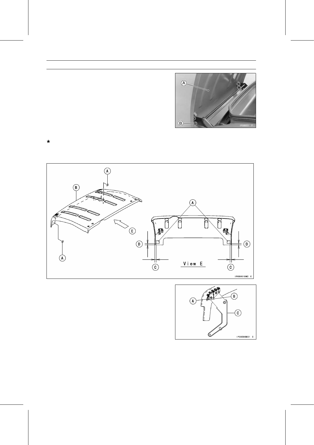
Front Cargo Hood Removal

•

Tilt up the cargo hood [A].

•

Remove:

Cargo Hood Mounting Bolts [B] and washers
Cargo Hood

Front Cargo Hood Installation

If the dampers [A] are removed from the front cargo hood
[B], install them as follows.

0

∼ 5 mm (0 ∼ 0.20 in.) [C]

2

∼ 5 mm (0.08 ∼ 0.20 in.) [D]

•

Installation is the reverse of removal, note the following.

○

Contact the bracket [A] of the front cargo hood and the
boss [B] of the arm [C].

FRAME 16-19

Front Cargo Compartment

If the hook bracket was removed from the front cargo
hood, install it as follows.

○

Tighten the bolts [A] while pushing the bracket [B] forward
[C].

Front Cargo Hood Cable Adjustment

•

Remove the front cargo compartment (see Front Cargo
Compartment Removal).

•

Loosen the adjuster mounting nuts [A], and slides the ad-
juster as shown in the figure.

20.5

∼ 21.5 mm (0.81 ∼ 0.85 in.) [B]

•

Tighten the adjuster mounting nuts securely.

Front Cargo Compartment Removal

•

Remove:

Front Fenders (see Front Fender Removal)
Coolant Reserve Tank (see Coolant Reserve Tank Re-
moval in the Cooling System chapter)

•

Remove:

Screws [A] and Collars
Tapping Screw [B] and Collar

•

Remove:

Side Mounting Bolts [A] (Left and Right)
Front Cargo Compartment [B]

Front Cargo Compartment Installation

•

Installation is the reverse of removal, note the following
parts size.

Screws [A] [L = 16 mm (0.63 in.)] and Collars [L = 4 mm
(0.16 in.)]
Screws [B] [L = 22 mm (0.87 in.)] and Collars [L = 6 mm
(0.24 in.)]
Tapping Screw [C] [L = 16 mm (0.63 in.)] and Collar [L =
4 mm (0.16 in.)]

16-20 FRAME

Cargo Bed

Cargo Bed Removal

•

Remove the rear fender assembly (see Rear Fender As-
sembly Removal).

•

Open the clamps [A] and disconnect the tail/brake light
lead connectors [B] (left and right).

•

Remove (Left and Right):

Bolts [C]
Tail/Brake Light Assemblies [D]

•

Open the steal clamp on the cargo bed and free the lead.

•

Unlock the hooks [A].

•

Raise the rear seat and push it toward the front seat back
to store.

•

Remove (Left and Right):

Snap Pins [A]
Cargo Bed Mounting Pins [B]

•

Remove the cargo bed.

Cargo Bed Installation

•

Installation is the reverse of removal, note the following.

○

Apply lithium grease (NLGI Grade No.2) to the cargo bed
mounting pins.

○

Check that the following are in place on the cargo bed and
frame.

Cargo Bed Rubber Dampers [A]
Frame Rubber Dampers [B]
Tail Gate Pivot Rubber Dampers (Left and Right)

FRAME 16-21

Cargo Bed

•

When the cargo bed is disassembled, note the following
when installing the plates and tail gate.

○

Be sure the clearance [A] between the back end of the
carrier [B] and the bottom of the tail gate [C] is more than
2 mm (0.079 in.) as shown in the figure (left and right).

○

Be sure the clearance [A] between the plate end [B] and
the tail gate end [C] is less than 5 mm (0.197 in.) as shown
in the figure (left and right).


Content   ..  107  108  109  110   ..