Kawasaki Diesel MULE 4010 TRANS 4x4 (KAF950G9). Manual - part 108
 

  Index      Engines     Kawasaki Diesel MULE 4010 TRANS 4x4 (KAF950G9) - service manual


Search            


Content   ..  106  107  108  109   ..


Kawasaki Diesel MULE 4010 TRANS 4x4 (KAF950G9). Manual - part 108


16-14 FRAME

Seats and Seat Belts

•

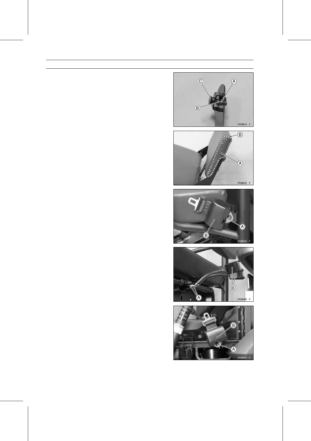
Remove (Left Side only):

Circlip [A]
Spring [B] and Pin [C]

•

Separate the upper lever from the bottom lever.

Rear Seat Installation

•

Installation is the reverse of removal, note the following.

○

Replace the removed nuts with new ones.

○

Install the rear seat back [A] so that its thicker side [B]
faces upward.

Seat Belt Removal

•

Remove:

Front Seat Belt Mounting Bolts [A]
Front Seat Belts [B]

•

Remove:

Front Seat Belt Buckle Mounting Bolts [A]
Front Seat Belt Buckles [B]

•

Remove:

Rear Seat Belt Mounting Bolts [A]
Rear Seat Belts [B]

FRAME 16-15

Seats and Seat Belts

•

Remove:

Rear Seat Belt Buckle Mounting Bolts [A]
Rear Seat Belt Buckles [B]

Seat Belt Installation

•

Tighten:

Torque - Seat Belt Mounting Bolts: 34 N·m (3.5 kgf·m, 25

ft·lb)

○

Install the front [A] and rear seat belts so that their instal-
lation angle is 40

∼ 60° [B].

•

Tighten:

Torque - Seat Belt Buckle Mounting Bolts: 34 N·m (3.5

kgf·m, 25 ft·lb)

○

Install the front seat belt buckles [A] so that their red but-
tons [B] face inside.

16-16 FRAME

Control Panel

Control Panel Removal

•

Remove:

Front Cargo Compartment (see Front Cargo Compart-
ment Removal)

•

Remove the bands [A] and clamp [B], and free the leads.

•

Disconnect:

Light Switch Lead Connector [C]
Oil Pressure Warning/Glow Plug Indicator Light Lead
Connector [D]
Speedometer Illumination Light Lead Connector [E]
Coolant Temperature Warning/Parking Brake Indicator
Light Lead Connector [F]
Power Steering Warning Light Lead Connector [G]
Hour Meter Lead Connector [H]
Main Switch Lead Connector [I]
Power Outlet Connector Lead Connector [J]
Fuel Gauge/Hour Meter Lead Connectors [K]
[L] KAF950G9

∼ GC/HA

[M] KAF950GD

•

Disconnect the horn switch lead connectors [A]
(KAF950GD).

•

Remove:

Bolts [A]
Speedometer Cable Upper End [B]
Speedometer [C] with Bracket

FRAME 16-17

Control Panel

•

Remove the steering wheel (see Steering Wheel and
Steering Shaft Removal in the Steering chapter).

•

Remove the control panel mounting screws [A] and col-
lars.

•

Open the glove compartment covers [A]

•

Remove the control panel [B]

Control Panel Installation

•

Installation is the reverse of removal, note the following.

○

Run the harness, cables and leads correctly (see Cable,
Wire, and Hose Routing section in the Appendix chapter).

Glove Compartment Removal

•

Remove:

Control Panel (see Control Panel Removal)
Screws [A]
Glove Compartment [B]


Content   ..  106  107  108  109   ..