Technology of watch production - part 74
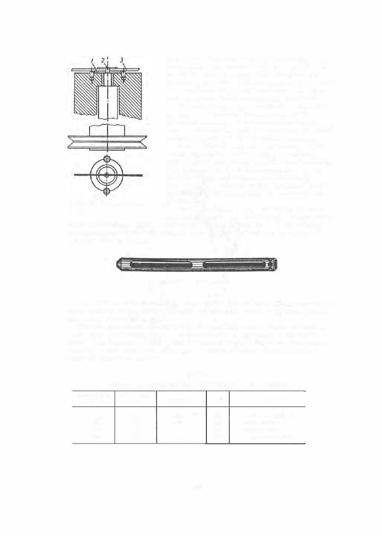
FIGURE 60. Hairspring-coiling
device
area of the barrel is filled by the blanks . The
strip ends which protrude are then cut off. The
barrel is easily removed from the shaft and
covered with a lid. The barrels are then placed
in a container (Figure 6 1 ) and loaded in a fur
nace for form - fixing (stabilizing) treatment.
The form - fixing heat treatment of the hair
spring, at a specified temperature and for a
specified duration, is performed for the pur
pose of causing the spring to maintain the spiral
form imparted to it by the coiling proces s .
Form fixing
is a critical operation. Very
small fluctuations in the process conditions
lead to sharp variations in the hairspring form .
The dependence of the hairspring form on the
heat-treatment conditions is illustrated in
Table 3 by the example of the "Molniya " pocket
watch hairspring (acc ording to laboratory ex
periments ).
The best results were obtained in the first
and fourth cases . No darkening of the polished
hairspring s urface during heating and cooling is permitte d . Accordingly,
hairsprings are now form -fixed in vacuum installations at a pressure of
1 . 2 X 1 o - 4 mm m ercury.
FIGURE 61. Barrel container
The UFV vacuum installation (Figure 6 2 ) used for form -fixing heat treat
m ent consists of two thermal blocks , an electric heater, a vacuum sys tem,
and a heating c ontrol panel .
The thermal blocks are cylinders 8 0 0 m m long and of 8 0 m m diameter,
made of heat- resis ting steel . They are fastened vertically to the panel
front. The hairspring containers are placed in six compartments sym m e
trically located inside the lower part o f thermal block ( 1 ) for a length of
about 4 0 0 mm from the end .
TABLE 3
Hairspring properties and form fixing as a function of the process conditions
Temperature,
Holding time,
au
kg/mm2
i,"/o
Results
·c
min
700
21
1 03
5 .6
Form normally fixed
680
19
1 03
5.6
Form not fixed
680
30
111
3 .2
Form not fixed
680
45
99
5.3
Form normally fixed
2 9 3