Technology of watch production - part 73
 

  Index      Books     Technology of watch production (Tarasov) 1964 year


Search            


Content   ..  71  72  73  74   ..


Technology of watch production - part 73


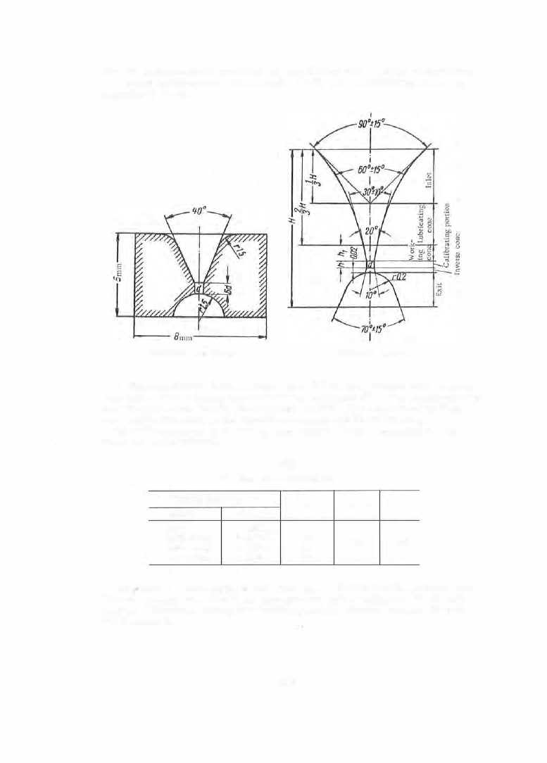
The  die  presents  three  sections :  an  exit  hollow  with  a  radius  of curvature 

1 .  5  and  working cone  with an angle  of 4 0°,  and  a  calibrating portion  of 

a  height  of 

a =  6d . 

FIGURE 5R.  Carbide die 

FIGURE  56.  Diamong die 

A  diamond  die  is  shown  in  Figure  5 6 .   I t  has four  working zones  and  an 

exit  cone .  The  entrance  has  cone  angles  of  9 0°  and  6 0° .   The  lubricant  cone 
has  an angle  of 3 0°  and the  working  cone  is  z oo.  The  calibrating  cylinder 

has  a  diameter equal  to  the  diameter required  for  the  hairspring. 

Specific  values of H,  h,  and h 1  (see  Figure  5 6 )  corresponding to  each 

draw are  given in  Table  1 .  

TABLE  1 

Dimensions of diamond dies 

Drawing diameter 

d, 

mm 

h, 

nominal 

tolerance 

0.003 

0.001 

0.003 to 0.06 

0.0015 

1 .2 

1 d  

2 d  

0.06 

to 

0.10 

0.0025 

1 .4 

0.10 

to 0.30 

0.005 

1 .6 

The  wire  is  drawn on the S - 64 M  machine .  The  lubricants  used are  vas e ­

line  oil  o r  soap  emulsion i n  the  first p a s s e s ,   and a viation fuel i n  the last 

passes .  The wire ,  during the drawing process ,  pas s es  between felt pads 

which clean it. 

2 89 

The  kinematic s  of the  S - 64M drawing machine  are  shown in Figure  5 7 .  

The  drawing speed i s  varied  (between  1 5  and  2 6 m / min)  by transferring the 
V-belt on the  4 - step  drive  pulley. 

FIGURE  57.  Kinematic scheme of the S-64M machine : 

1 -die :  2-drawing pulley:  3-winding reel:  4-stock  reel:  5-guide idler. 

Technical data,  S-64M machine 

Maximum drawing  diameter,  mm 


Drawing-pulley speeds,  rpm 

.


Drawing speed,  m/min 

.

.

.

.

.

.

.

.


Electric motor 

.

.

.

.

.

.

.

.

.

.

.

.

.

.


TABLE  2 

0.5 

80, 96, 115, 137 

15-26 

0.6 kw, 
1400  rpm 

Drawing sequence 

Drawing sequence 

die-plate 

Drawing 

die-plate 

coefficient 

speed*, 

coefficient 

draw, mm 

diameter, 

of draft, 

"/o 

m/min 

draw, mm 

diameter, 

of draft, 

"/o 

mm 

mm 

0.3o--0.27 

0.270 

19 

15-18 

0.14o-- 0.130 

0.130 

13.5 

0.27- 0.240 

0.240 

21 

15-18 

0,13o-- 0.120 

0.120 

14.5 

0.24o-- 0.220 

0 .220 

16 

15-18 

0.12o--0.110 

0.110 

16 

0.22o-- 0.200 

0 .200 

17 

15-18 

0.11o-- 0.100 

0.100 

17 

o.zoo-- o.180 

0.180 

19 

15-18 

0.10o-- 0.095 

0.095 

10 

0.18o-- 0.170 

0.170 

11 

15-·18 

0.095-0.090 

0.090 

10 

0.17o-- 0.160 

0 .160 

11.5 

15-18 

o.o9o-- 0.085 

0.085 

11 

0.16o-- 0.150 

0.150 

12 

15-18 

0.085- 0.080 

0.080 

11 

0 .1 5o-- 0.140 

0 .140 

13 

15-18 

o.o8o-- 0.075 

0.075 

12 

Drawing 

speed 

m/min 

15-18 
15-18 

15-18 

15-18 

22-26 
22-26 

22-26 

22-26 

22-26 

The tolerance on dimensions > 0.200 mm = 

± 

0.002.  The tolerance on dimensions < 0 .200 mm = 

± 

0.001 mm. 

•  The drawing speed has been increased 4 to 5 times in latest drawing machines. 

290 

Table  2  gives  the  drawing sequence for the  "Pobeda" watch hairsprings 

made  of N 3 5KhMV alloy. 

Flattening of the wire  is  performed in  the  special D - 6 3  two-high  rolling 

mill  (Figure  58 ).  The  design  diameter 

Dn 

is  determined using the  empirical 

formula 

h + b  

where 

the  hairspring thickness; 

the  hairspring width. 

For the  " Pobeda"  watch hairspring  this  formula  gives 

D  - 0.035 + 

0.12 

0 0775 

n -

m m .  

For high  values  of 

a u  

the  value 

D n  

0 . 0 7 5  mm is used. 

Flattening is possible if 

� 

<;; 

1 0.  If

� 

is  more  than  1 0,  rolling will  not 

produce the  required  width but will  increase the length instead .  

The 

ratio  for the  hairspring being discussed her.e 

( h 

0 . 035 mm, 

b = 

0 . 1 2  mm )  is 

3 . 4 ,   which  is  well below the  upper limit.  The  quality 

of the  strip  surface  is  a  function  of the  state  of the  roller  surfaces  only. 

The  surface  quality of  the  strip  must be class  1 1  or  12  in  order  to  pro ­

tect the  hairspring from  corrosion.  The lateral edges  of the s trip  inevitably 

have  microfractures  resulting from  the  flattening,  and their  surface  quality 

is  class  8  or  9 .  

FIGURE 5 8 .   D-63 two-high rolling mill 

29 1 

Section AA 

FIGURE 59.  Diamond die 

A  certain  wavines s  is  imparted to the  s trip  surface by the  unavoidable 

roller  run- out.  The  wave  length is  equal  to  the  roller  circumference .   A 

run- out tolerance  of  0. 002 mm  is  established for the  rollers  in  order to 

minimize  thes e  fluctuations  and,  in addition,  the  strip  is  subsequently drawn 

through  a  diamond  die  (Figure  5 9 ) .   Ring  ( 1 )  holds  the  two adjustable man­

drels (2 ),  with  diamond  grains cemented in them . 

Technical data,  D-63 machine 

Maximum wire diameter,  mm . 

• 

.  . 

.  . 

.  •  •  . 

•  • 

.  • 

Normal rolling thickness,  mm 

.  • 

•  • 

.  . 

.  . 

.  • 

.  .  . 

0.03-0.05 

Rolling accuracy,  mm 

• 

•  • 

.  • 

.  • 

.  • 

.  . 

•  •  •  •  •  . 

0.001 

Roller diameter,  mm 

• 

•  . 

.  • 

.  • 

.  •  •  • 

•  •  •  •  •  •  . 

84 

Roller width,  mm 

.

.

.

.

.

.

.

.

.

.

.

.


60 

Average rolling speed,  m/min 

.


.

 ,  .

.

 , 


15 

Power required, 

kw 

• 

• 

• 

• 

• 

•  •  •  • 

•  • 

•  • 

• 

•  •  •  •  • 

• 

• 

0.5 

The  strip  thickness is  inspected using a  lever micrometer with scale 

divisions  of  0 . 00 1  m m .  

Coiling the  hairsprings. 

The flattened  strip  is wound on a  reel  of cir­

cumference  equal  to  (or double )  the blank length,  and cut by hand scissors; 

for this  purpose the reel has a  longitudinal slit.  The blanks  are then  coiled 

in barrel devices in  groups  of  3,  4  or  5 .  

The  scheme o f  a  device used f o r  the  simultaneous  coiling o f  four hair­

springs  is  shown in Figure  6 0.  The  barrel has two  diametrically opposite 

slots .  The barrel  ( 

1 )  

is a  running fit on the  shaft  (2 ).  A  slot is  milled  in 

the  shaft face ,   and two  strip blanks  ( 3 ),  twice as long as the blank length 

required  for  a  single  spring,  are  placed in  it.  The  shaft is  rotated by the 

drive,  and  the  hairsprings  coil up .  Two  cutouts  on the  external  shoulder 

of the  barrel  which  engage  two  pins  and thus position the barrel  in  the  de­

vice  prevents  its rotation.  The  coiling  continues  till  the  whole  internal 

2 9 2  


Content   ..  71  72  73  74   ..