Technology of watch production - part 72
 

  Index      Books     Technology of watch production (Tarasov) 1964 year


Search            


Content   ..  70  71  72  73   ..


Technology of watch production - part 72


the  production rate for  each operation are not calculated,  but  are  established 

in accordance  with the machine  kinematics .   Each  ope ration  is followed by 
either random  or  1 0 0 o/o  inspection . 

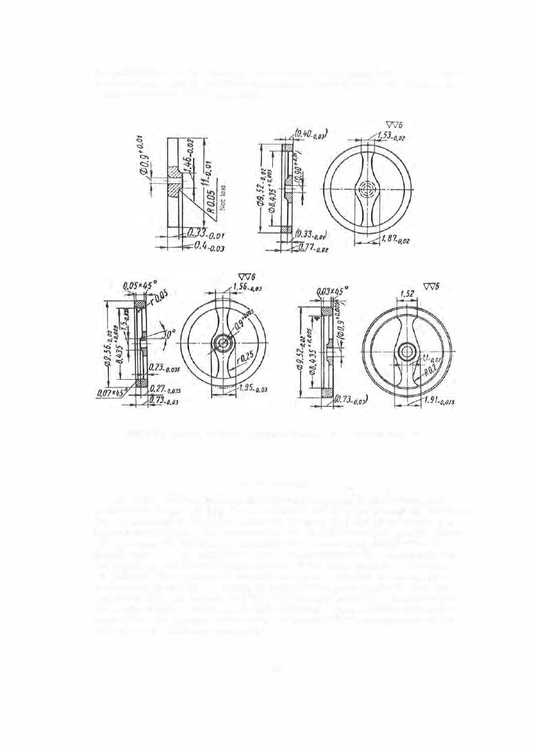
FIGURE  50.  Operational sequence  of the process of balance-rim manufacture by swaging 

THE  DOUBLE  ROLLER 

The  double  roller performs  the  following functions  in  the  escapement. 

It transmits  impulses  from  the pallet fork  to the  balance  through  the  impulse 
p in  (1 ),  mounted in the  upper  roller (2 )  (Figure  5 1 ),  and  so maintains  the 

balance  oscillations .   The  lower  roller  ( 3 ),  in its  interaction with the  guard 

pin,  prevents  the  pallet  from  unlocking  the  escape  wheel  except  when  the 

impulse pin is  in the  pallet fork  notch.  The  friction in the  contact between 
the  guard pin and the cylindrical surface  of the  rolle r  must be a  minimum . 

To  that  end,  the  surfaces  of  the  lower  roller are polished to  a  class  1 0  or 1 1

surface - fir �sh  quality.  A  hollow is  milled in  the  lower  roller to pass  the 

guard - pin  when the  balance  and  the pallet fork are in contact.  Double rollers 

are made  of brass ,  beryllium  bronze and steel .  Brass  rollers  give satis ­

factory results,  but  the  best results  are  obtained by hardened  steel  rolle rs 

with  polished  cylindrical  surface s .  

2 8 5  

The  impulse pin  works in impact,  and,  accordingly,  it must be  rigidly 

fastened to  the  uppe'r roller.  The  hole  for  the  impulse pin must be posi-

FIGURE 51 .  Double roEer 

!-impulse pin;  2-upper (impulse) roller; 
3-lower (safety) roller. 

tioned  symmetrically relative  to  the 

lower rolle r  hollow and  its  center  must 
be on the  same radius with that of the 

center  of the hollow. 

The b rass  doubl e - roll e r  blanks,  which 

have  a  class  7  or  8  surface-finish  quality, 

are turned on Swiss - type automatic  s crew 
m achines  (Figure  52,  a) and the central 

hole  is  then  countersunk from  the  uppe r  

roll e r  side o n  the  S- 3M drilling machine . 

The  central hole  is  then  shaved to  a 

diameter  of  0 . 4 3+ 0 . 0 1  (Figure  5 2 ,  b )  on 

the S - 1 0 bench power pres s .   This is 

followed by the piercing of the  hole  for 

the  impulse pin in the  upper  roller,  and 

the  punching  of the  hollow for  the  guard 

pin  in  the  lowe r  roller.  These ope ra ­

tions  a r e  perform e d  b y  a  combination 
die  in  the  S- 1 0  pre s s .   The  maximum 

allowable  shift of the  hollows  relative 

to  the  axis  of symmetry  of the  impulse 

pin is  0 . 01 5 mm. 

The  safety  roller s urface  is  then 

shaved to a \l'V'V'V 1 0  finish in a  special 

die .  The  permis sible  run- out  of the 

surface  relative  to  the  central  hole  is  0 . 0 1  mm .  The  roller to  be  shaved is 

placed  on the  bushing  ( 6 )  (Figure  5 3 )  in the lowe r  base  ( 1 )  and  positioned by 

the  roll e r  hole  on  guide  pin  (2 ) .   The  upp e r  d i e  ( 3 ),  with the bushing  (4 ) 

fixed in  it,  shaves  the  surfac e .   The  knockout  ( 5 )  removes the  roller from 

the die  after  the bushing (4 )  has been withdrawn upward. 

The designs  of die  ( 3 )  and bushing  (4 )  are  shown in Figure  53,  b. 

FIGURE 52

Operation drawings for the double roller: 

a-screw-machine blank;  b-hole shaving. 

2 8 6  

FIGURE  53.  Shaving die for the cylindrical surface of the double roller 

a -general view ;  b-die. 

THE  HAIRSPRING 

The  balance  and  hairspring  are  the  most critical  assemblies in the  watch 

m ovement.  The hairspring must  pulsate  ( vibrate )  uniformly in  coiling  and 

uncoiling,  and  the refore  the  spiral coils  must not  touch  during their opera­

tion.  The  terminal  curves  must be  s o  shaped that the  center  of gravity of 

the hairspring coincides  with its  geometrical  c ente r .   The temperature 

coefficient of the  material  from  which pocket- and  wristwatch  hairsprings 

are  made  must  not e xceed  0 . 5  s ec / deg. c ent .  The  surface-finish  quality 

must  be  class 

1 1  

o r  

12. 

The  blank of the  "Pobeda "  wristwatch  spring is shown  in Figure  5 4 .   The 

spiral  thickness is 

0 . 03 5± 0 . 0 0 1  mm.  The  reason  for  the  narrow tolerance 

is that in the formula for the  constant 

of the hairspring moment 

appears  to  the  third power,  so  that  small thickness  deviations lead  to  a 

considerable  variation  in  the  hairspring m oment.  Hairsprings  are  manu­

factured by  repeatedly drawing  wire,  flattening it,  cutting it to blanks  of 

the  required length,  coiling the blanks  in a  barrel  (in groups  of four )  to  give 

them  the  shape  of an A rchimedean spiral followed by heat treatment of  the 

coiled springs  in order to  stablize  their  shape  (form  fixing),  and lastly  se­
paration of the  stabilized hairsprings . 

2 8 7  

The  hairsprings  are  inspected  for  moment,  surface  quality  and  spiral 

shap e .  

Q12+0Jq 

6.12+6.* 

FIGURE 

54. 

Blank  of " Pobeda''  watch hairsprings 

Drawing. 

The  wire used fo r  hairsprings,  of  0 . 2 6 - 0 . 3 0  mm  diameter, 

is  made  from the N3 5KhlVIV alloy and has the following p roperties :   bright 

surfac e ,   ultimate  tensile  s trength 

o u =  

7 8 to 8 8 kg/mm 2 ,  elongation 

1 7  to 

2 0 o/o,  and  modulus  of elasticity 

E =  

1 8 , 5 0 0  to  1 9 , 5 00 kg/mm2 . 

The  wire  is  drawn,  in  the  watch plants,  in  several  stages  to  the  design 

diameter 

(D,.). 

The number  of  draws  is  determined from  the  difference be­

tween the  wire diameters in the  initial  and  final  drawing  stages,  taking into 
account  its  mechanical  p ropertie s .  

o r  

A  reduction coefficient 

i s  calculated from  the  formula 

h = Fn-1 - F" . JOOOfo 

F,_l 

h = 

D�_1 - D� 

D�-1 

for  each  pass  or  group  of passes , 

where 

reduction coefficient in 

o/o, 

Fn_1 

cross - s ectional area of the wire  after  the  preceding pass ,  m m2 ; 

F71 

cross - s ectional  area  of  the  wire  after the  given pass ,  mm2 ; 

D,._1 

and 

D,. 

corresponding wire  diamete rs . 

The  reduction coefficient for  the  first drawing stage  is  1 9  to  2 0 o/o  and 

for the  final  stage  it is  1 0  to  12 o/o.  The  reason for this is that the  wire 

work - hardens  with  the  drawing,  and 

ou 

increases  to  1 2 5  kg/mm 2 .  The 

speed  of drawing is  increased  somewhat by reducing the  reduction coeffi­

cient.  The  speed  is  1 5  to  1 8 m /m in  at  the  beginning,  and  22  to  2 6 m / min  in 

the  end. 

The  wire  is  d rawn  from  0 . 3 0  mm  diameter to  0 . 2 0  mm  diam eter through 

carbide  die s ,   and from  0 . 2 0  mm  diameter to  its  final  dimension of  0 . 0 7 5  to 

0 . 08 mm  (or  0 . 055 m m )  through  diamond  dies . 

Drawing  dies  are  manufactured according to  GOST  3 9 1 9 - 4 7  and  6 2 7 1 - 52 .  

A  carbide  die  of 8 m m  outer diameter  and  5 m m  height i s  shown  in  Figure 5 5 ,  

2 8 8  


Content   ..  70  71  72  73   ..