Technology of watch production - part 71
 

  Index      Books     Technology of watch production (Tarasov) 1964 year


Search            


Content   ..  69  70  71  72   ..


Technology of watch production - part 71


The  balance  of  " Pobeda "  watches  is  blanked  from  strip  material  in  a 

combination  die  (first ope ration,  Figure  3 9  ) .  

Blanking and  shaving are  followed b y  stress  relief (s econd  operation ) .  

The purpose o f  stress - relieving heat treatment  (used in  watch p roduction 
for  brass  and nickel - silve r  parts )  is  to  eliminate  the  further  deformation 
of parts  after mechanical  treatment .  The  hardness of the  metal  is not 

impaired  by  this  process . 

0952-o.oz 

08.80.002 

<:; 

;::,.' 

� 

Positional tolerance  for the threaded 

holes: 

± 

0'30' 

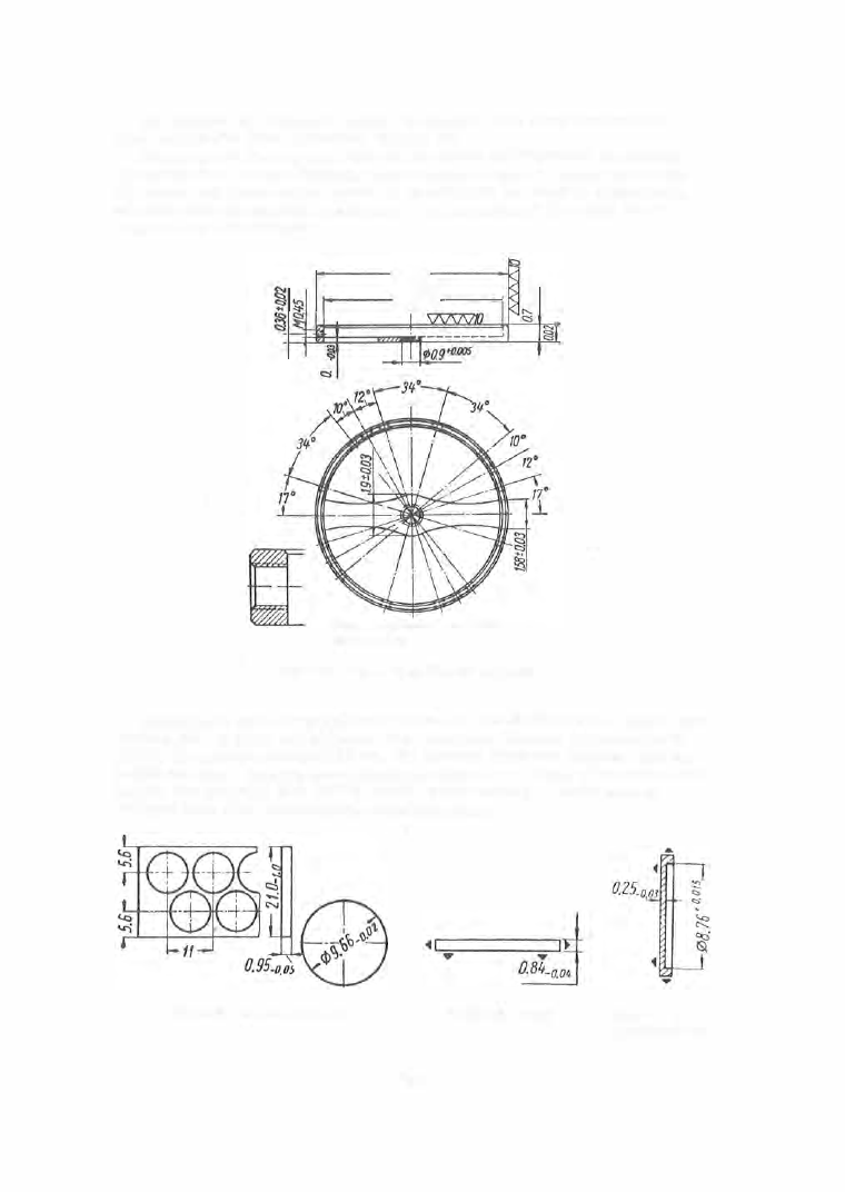
FIGURE 38.  Balance of the " Pobeda"  wristwatch 

Watch  parts  are  stress-relieved  in  the  PN- 3 1 6  shaft furnace,  whose pro­

duction rate  is  up to  1 00 kg/hour .  The  maximum  furnace  tempe rature  is 

6 50°C ,  the  powe r  consumed  24 kw,  the  internal  diameter 400 mm,  and  the 

height  500 mm .  The  stress-relieving conditions  for  nickel-silver  are:  heat­

ing for  two hours  at  340- 3 6 0°  followed by air cooling.  The  furnace  is 

charged with  5000 - 2 0, 000 parts  simultaneously . 

FIGURE  39.  Preparing the blank 

FIGURE 

40. 

Facing 

2 8 1  

FIGURE 41 .  Recess­
ing from the die side 

Some  shaft furnaces  have  forced air  circulation  to achieve  a  more  uni ­

form  heating  of  the  parts . 

If  no  shaft furnaces are  available,  s tress  relieving  can be  carried  out  in 

an  oil  bath .  The  oil-bath  p rocess  is  more  expensive,  howeve r,  because  a 

considerable  quantity  of  oil  and  washing compound  is  consumed .  The capac ­
ity  of  a  bath  is  usually  one  half  or  one  third  that  of a  shaft  furnace . 

The stress - relieved balance  blanks  are  the n  washed according to  the 

s tandards  (third  operation ) .  

The  blank i s  [aced  (fourth  operation,  Figure  4 0 )  in  autom atic  machine s 

with  magazine  loading,  and  then  recessed  (fifth  operation,  Figure  4 1 ).  This 

operation  removes  a  layer  of metal  and  provides  a  holding surface for  the 

following ope ration . 

The  s ixth  ope ration  (Figure  42 ),  performed  on  the  Sh- 06  hydraulic  p re s s ,  

consists  in  piercing  the  windows ,  piercing  the  c entral  hole  and  shaving 

the  oute r  and  inner  rim  diameters .  The  run- out  of  the  outer  and  inner 

diameters  relative  to  the  central  hole  afte r  this  operation  must  not  ex­

ceed  0 . 02 mm . 

FIGURE 42.  Piercing the windows 
and the central hole,  and shaving 

the rim 

FIGURE 43.  Coun­
tersinking the cen­
tral hole 

FIGURE 

44. 

Drilling 16  holes 

The  c entral  hole is  then  countersunk  (seventh  operation,  Figure  4 3 ),  and 

1 6  radial  holes of  0 . 3 6 5  mm  diameter are  drilled in a  semiautomatic  hori­

zontal  drilling machine  (eighth operation,  Figure 44 ).  All the holes  must be 

d rilled at the  sam e  distance from  the  lower fac e .  

Next,  the  upper face  o f  the  rim  is faced  and a  chamfer  turned  in  a  spe­

c ial  semiautomatic  machine  (ninth  operation,  Figure  4 5 ) .   The  nonparal ­

leleity  of  the  faces must  not  exceed  0 . 0 1 5 m m .  

The  outer  diameter o f  the  balance  rim  is then  turned  o n  special  semi­

automatic  machines  in order to  elim inate  run - out and to remove  burrs 

resulting from  the  drilling of the  screw holes  (tenth  ope ration,  Figure  46 ) .  

The  maximum  permissible  run- out is  0 . 0 1 5  m m .  

The  rim  holes a r e  next tapped o n  the  S - 7 2   m achine  with  manual  head­

s tock feed  (eleventh  operation,  Figure  4 7 ) .  

The last operation i s  the polishing o f  the  upper face o f  the balance  which 

is done on the S- 1 2 2  machine  (twelfth  operation,  F igure  4 8  ). 

The T - 2 2 9  semiautomatic  m achine  (Figure  4 9 )  was  especially designed 

fo r  the machining of the balance  rim ,  with  the twin  aims  of increasing the 

p rocess  accuracy and  reducing the number of operations . 

1174 

2 82 

The  machine  is  equipped  with  five  tool  slides .  The  following operations 

are  performed  in  one  chucking of the  balance :   turning the  outer and  inner 

diameters,  facing,  turning  two  chamfers,  and  boring a  hole .  The  spindle 

revolves  at  30, 000 rpm ,  corresponding to  a  cutting  speed of  900 m l min. 

Carbide - tipped and  ruby-tipped  tools  are used.  The circular and  face 

run- out  tole rances are narrowed to  0 . 01  mm,  and  the  surface quality is 
improved  to  class  1 1 .   The  time  taken by  one  cycle varies  between  1 0  and 

2 0  sec.  The  machine  performs  operations 9,  1 0  and 1 2  of the above indica ted .  

0. 75-o.oz 

0.07x�.SO 

FIGURE 45.  Facing 

the upper face and 

chamfering 

FIGURE 46.  Turning 
the outer diameter 

FIGURE 47.  Tapping the 16 holes 

FIGURE 48 .  Polishing 
the upper  face 

The  balance  is  located  and  positioned  on  a  mandrel  according to  the  inner 

rim  diameter at a  height e qual  to  the  central  arm  thickness . 

In  addition  to  the  improvement  of  the  machining m ethods,  attempts  are 

being made  of late  in watch plants  to  manufacture  the balance rim  by  swag­

ing.  The  balance  of  "Zvezda"  watches  is blanked in a  c rank  press  from  a 

strip,  with  preliminary d rawing  of  the  hub  (Figure  5 0 ,   a ). 

The  blanked part  is  subjected  to  a  preliminary  forming of  the  rim,  the 

hub,  the  central arm,  and the  windows  are  pierced (Figure  5 0,  b ) .   The 

operation is  performed in  a  die  on embossing pres s es  or  friction presses 

(or in crank presses if the above - mentioned types are not available ).  The 

formation of a hub of  0 . 4  mm  height  is  an unavoidable  result of the  flow  of 

material  during forming.  The  preliminary forming is followed by the  final 

forming  of  the  rim  and  cold  working  of  the  central  arm  (Figure  5 0 ,  c ). 

The  hole  is  s haved  to  its  final  dimension .  A  0 . 1 5 mm  local  growth of the 

rim  thickness  occurs  in  the  dotted  zone  and  is  removed in the  following 

operation by grinding with  an  emery wheel. 

The balance  obtained by the  swaging method is  then  shaved in a  die on 

its outside and  inside  diameters and on the central arm contour (Figure 50, d ), 

after which  it  is  subjected to  a  stress-relieving operation. 

Drilling,  countersinking,  and thread tapping,  are  carried out in the  same 

way  as  was  described  earlier. 

The  s waging m ethod  is  more  productive  than  the  machining p roces s :   the 

number of operations  is  greatly  reduced,  and  the  time  consumed is  1 I 3  to 

1 I 4  of that  required by  machining. 

Machining is  followed by balance  ass embly:  the  screws  are  screwed into 

the  rim ,  the  staff  is  introduced into  the  hol e ,   and  the  balance  is  compen­

sated .  Since the mechanical  operations  (the  press  operations  excepte d )  are 

conducted on special  [semiautomatic ]  machines,  the  cutting conditions  and 

2 83 

FIGURE 49.  T-229 semiautomatic finish-turning machine : 

a-general vie\v ;  b-kinematic scheme. 

2 8 4  


Content   ..  69  70  71  72   ..