Technology of watch production - part 69
 

  Index      Books     Technology of watch production (Tarasov) 1964 year


Search            


Content   ..  67  68  69  70   ..


Technology of watch production - part 69


Profile of the 

�-

FIGURE 21.  Parts of the  die for blanking and shaving the pallet lever: 

a-die (sectional);  b-die-mounting ring;  c-upper knockout;  d- contour punch. 

2 7 3  

and  the  ring is  held in  the  upper shoe of  the  die  set.  The  knockout  (Figure 

2 1 ,  c ),  whose profile  is  a  close-running fit in the  die  profile  passes  through 

the  die  and  ring.  The  design  of  the  punch,  which  is  mounted in  the  lower 

shoe ,   is shown  in  Figure  2 1 ,  d.  The punch  profile  is  ground  according to 

the  die p rofile  with  a  clearance  of 0 . 0 1  mm  on each  side  at the  expense of 

the punch. 

FIGURE 22.  S-45  two-spindle horizontal milling machine 

0.2-o.oz 

FIGURE 

2 3 .  

Milling two steps 

FIGURE 24.  Piercing four holes 

2 7 4  

The  blanked pallet leve r  is  then  transferred to  the  S - 4 5  two - s pindle  ma­

chine  (Figure  2 2 )  where  the two steps are milled  (second  operation) (Figure 
2 3 ).  The  machine  is equipped  with  a  rotary table  (4 )  (Figure  22 )  on  which 

are  mounted  two  five - place  chucking  fixtures  with  contoured  plates  to  take 

the  pallet-lever blanks .  New blanks are  loaded  in  one  of  the  fixtures  while 

those in the  other are  being milled.  The  pallet-lever faces  are milled  con­

secutively by  the  cutters  in the firs t and s econd  spindles.  The  worktable 

is  fixed  during milling,  while  the  cutter  table  ( 3 )  move s .  

Technical data,  S -45  machine 

Spindle speed,  rpm 

•  •  .  •  •  •  •  •  •  •  •  •  •  •  •  •  •  •  • 

220(}-4000 

W orktable diameter,  mm 

•  •  •  •  •  •  •  •  •  •  •  •  •  •  • 

160 

Production rate,  pans/shift 

•  •  •  •  •  .  •  •  •  •  •  •  •  • 

4000 

Electric motor 

0.75 kw, 
1440 rpm 

The  m illing of the  lever  steps is  followed by the piercing of two  circular 

holes  for the arbor and the guard pin,  and two  contoured holes  at the places 

where the pallet slots  are  to  be situated  (third operation )  (Figure  24 ).  The 

piercing is performed in  the  Sh- 04  die .   The  location o f  the  contoured holes 

is  so  chosen  that  recesses  of  0 . 03 - 0 . 0 5  mm depth remain on the  outer  side 
of each slot after the  slots  are  milled.  The pallet stone  is thus caused to 

fit  closely the  inner  side  of the slot  (Figure  2 5 ,  a ).  Figure  2 5 ,  b  shows  the 

position  of  a  pallet  stone  in  a  slot without  a  reces s .   The  correct disposition 

of the  four  holes  relative  to  the pallet contour  is  achieved  by piercing them 

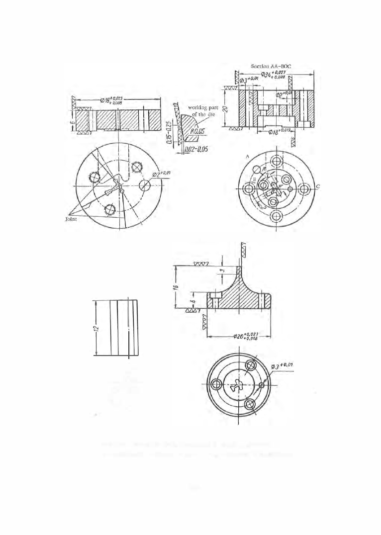
simultaneously.  The  die  (Figure  2 6 ,   d)  used  must be accurate. 

FIGURE 25.  Shape of the pallet-stone slots in the pallet lever 

The  punches  (Figure  2 6 ,   a ),  the  punch holder,  and  the  stripper  (Figure 

2 6,  b  and  c )  are  mounted in a  ring. 

The next  (fourth )  operation is the  countersinking  of the holes ,  performed 

on the S - 3  m  machine .  The  fifth  and  sixth  operations  are  the  m illing  of  the 

fork  and  the  stone  slots  (Figures  2 7  and  2 8 ),  on the  S - 4 7  and  S-48 machine s, 

respectively.  The  production rate  of the  S - 4 8  machine  (Figure  2 9 ),  which 

uses a  slotting  milling  cutter for  milling the pallet- stone  slots ,  is  3000 parts 

per  shift .  The following  (seventh )  ope ration  is the  calibration  of the  coni­

cal hole  (Figure  3 0) to  take  the conical  portion  of the arbo r .   This opera­

tion is  performed  on a  hand  pres s .  

2 7 5  

FIGURE 26.  Shaving die for the four holes  in the pallet 

a-punch;  b-punch holder;  c-stripper with insert;  d-die. 

0. 1 

FrGURE 27.  Milling the fork  and 

the  impulse pin slot 

FIGURE 28.  Milling the pallet-stone 

slots 

The  palle t  leve r  is  then  hardened  and  tempered to  Rc 

53  - 5 5  (eighth 

operation),  after which  the  impuls e  pin  slot curves  are  polished  (ninth 

operation ) (Figure  32 )  on the  S - 1 3 1  machine  (Figure  3 1 ) . 

An  oval  shape  is  given  the  slot walls  in  order to  reduce  the  surface  of 

contact with  the  impulse  pin  and  to  increase  the  surface-finish quality  from 

class  7  to  class  1 0 - 1 1 .  

The polishing operation  is  conducted  as  follows .  The  pallet lever is 

clamped in a  fixture  in the chuck  ( 1 )  (Figure  3 1 ).  The  spindle  with the A Z  

polishing wheel is  mounted on the  slide  ( 2  ).   The  link  system  ( 3 )  imparts 

an oscillating motion to  the  chuck carrying the  pall e t  leve r .   The  wheel 

penetrates into the  slot opening and rounds off the  sharp  e dges .  The  right­
hand upper  edge and the left-hand  lower  edge  are first  rounded off  simul ­

taneously,  and i n  the  next  oscillation the left-hand upper e dge  and  the  right­

hand lower  edge  are  rounded- off  simul taneously. 

2 7 6  


Content   ..  67  68  69  70   ..