Technology of watch production - part 67
 

  Index      Books     Technology of watch production (Tarasov) 1964 year


Search            


Content   ..  65  66  67  68   ..


Technology of watch production - part 67


4  5 

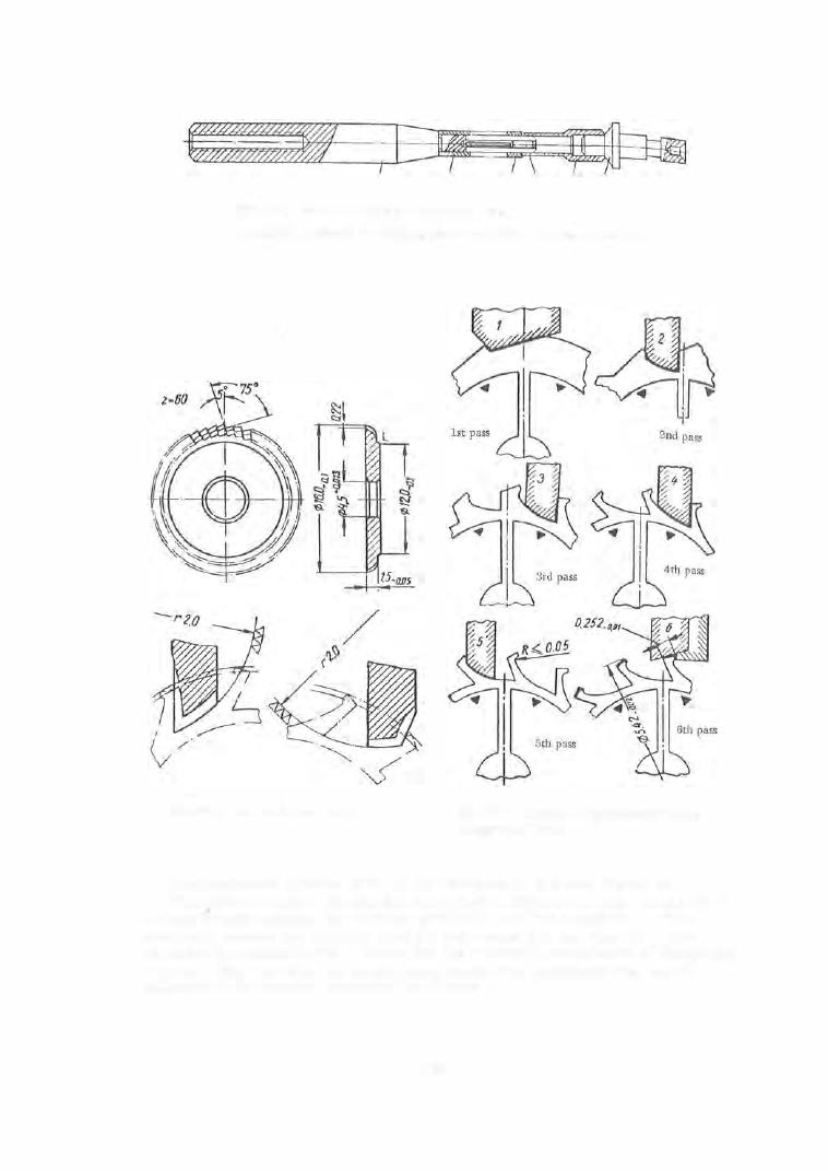
FIGURE  5.  Mandrel for milling escape-wheel teeth: 

1-mandrel;  2 -sleeve ;  3-clamping piece;  4-washer;  5- inscrt:  6-holder. 

FIGURE 6.  Fine-tooth formed cutter 

FIGURE 7.  Sequence of operations in milling 
escape-lvheel teeth 

The  kinematic  s cheme  of  the  S - 1 09  machine  is  given in  Figure  8 .  

The  electric  motor rotates  the  driveshaft I  (Figure  8 ),  and,  via a  series 

of belt transmissions,  the  milling  spindle  ( 1 )  and the  cam shaft II.  The 

cam shaft  rotates  the  dividing  head  (2 )  and  moves  the  carriage  ( 3 )

The 

machine  is  equipped  with  a  device for  the  automatic  switchover  of  the spindle 

barrel .  Each  spindle  has  an adjusting device  for pos itioning  the  spindle 

relative  to  the  mandrel  carrying  the  blanks . 

2 6 5  

Technical data,  S-109  machine 

Milling length,  mm  . . . . . . . . . . . . . . .  . 

Maximum  axial  spindle travel,  mm  . . . . .  . 

Maximum diameter of milled wheel,  mm  . .  

Spindle speed,  rpm  . . . . . . . . . . . . . . .  

Milling speed,  m/min . . . . . . . . . . . . . .  . 

Camshaft  speeds,  rpm  . . . . . . . . . . . . . .  . 

Feed per cutter revolution,  mm  . . . . . . .  . 

Electric motor  . . . . . . . . . . . . . . . . . . .  . 

Production rate  . . . . . . . . . . . . . . . . . .  . 

5- 30 

1 0  

15 

1770 

90 

4.2;  3 ;   2.1 

0.008- 0.086 

0.5 kw,  1500 rpm 

650-750 wheels/shift 

FIGURE  9.  General view  of die for blank­

ing escape-1vheel teeth: 

FIGURE 8.  Kinematic scheme of the S-109 machine 

1-upper shoe ;  2-punch;  3-key;  4-stripper ; 
5 -srripper pin;  6-screw;  ?-spring plate; 
S-lower shoe;  9-die;  10-key;  11 -nest ; 
12-knockout. 

Some  watch plants  blank  out  the  wheel  teeth  so  that  the  m illing becomes 

unnecessary.  Although  this  method is more  productive ,  the  design  of such 

a  die  is  complex  (Figure  9 )

and  the  service life  of punch  and  die  is  short. 

The punch  (2 )  is  tightly fitted  into the upper  shoe  (1 ) .   The key ( 3 )  locks 

the punch  teeth  in a  fixed  position.  The  stripper  (4 )  is  fastened by m eans 

of the  three  stripper pins  (5 )  and  the  screws  (6 )  to  the  spring plate  ( 7 ) .  

The  die  ( 9 )  i s  tightly m ounted i n  the  lower shoe  (8 ) .   The key  ( 1 0 )  l ocks 

the  die  in a • fixed  position.  The  nest ( 1 1 )  positions  the wheel blank relative 

to  the  die .  The  knockout  ( 1 2 )  is  mounted  inside  the  die . 

The  working part  of  the  punch  (2 )  (Figure  1 0,  a )  is  manufactured  with  an 

allowance  for  grinding  and  polishing  the  teeth.  T he  die  ( 9 )  is  broached by 

2 6 6  

the  punch.  Wheel blanks  for this  die  (Figure 

3 )  

are blanked to a  diameter 

of 

5 . s o±0 . 03, 

while  wheel blanks  which  are  to  be  milled are blanked to 

5 . 57±0 . 0 3 .  

The  knockout  ( 1 2 )  (Figure  9 )  consists o f  a  base  and  a  ring with  the  work

­

ing  contour  which  is  a  clos e-running fit  in  the  die  (Figure  1 0, b ) .  

Punch 

Tolerance 

FIGURE 10.  Parts of the die for blanking the escape 1vheel : 

a-punch;  b-knockout  (compound). 

The  central  hole  in  the  escape  wheel  (Figure 

1 1 )  

is  pierced by a  punch. 

The  wheel is  located according to the  outside  diameter of the  teeth.  The 

tolerance  on the  hole  diameter is 

0 . 005 

mm  and  the  permissible  run- out on 

FIGURE 11.  Piercing the 
central hole  of the  escape 

the  outside  diameter is  0 . 0 1 5  m m .   The  piercing is 

followed by hardening  and  tempering to  Rc 

= 53 - 55, 

after which the  wheel  i s  fed t o  the  S- 1 5  machine for 

surface  grinding and polishing (see Chapter IX).  The 

impulse face  and locking face  are  finish-machined 

in  the  S - 1 2 5A  and  S - 1 2 6A  machine s .  

The  impulse  face is  ground o n  the  S - 1 2 5A  machine 

(Figure  1 2 )  and the  wheel  is located by the  central 

hol e .   One  escape  wheel  is  held  on the  mandrel . 

The  wheel  diameter has  an allowance  of 

0 . 0 3  

mm 

for grinding.  The  impulse  face  and  the  side  chamfe r 

are  ground  in  one  chucking  (Figure  1 3 ).  The  dia­

meter  tolerance  is 

0 . 0 1  

m m ,   and the permissible 

run- out  is 

0. 005 

m m .   The  impulse face  is  ground 

by  abrasive  wheels  of grain  size  240 at  a  speed of 

2 - 1 2 m / se c .  

The  kinematic  diagram  o f  the  S - 1 2 5A  machine 

is  given  in Figure  1 4 .  

2 6 7  

The  two - s tep  pulley  on  the  electric  motor shaft  drives  the  driveshaft I 

through  round belt s .   Three  three - s tep pulleys  are  mounted  on  the  drive­
shaft;  they  drive  the  longitudinal  and  lateral  grinding  quills  through  round 

belts ,  and the  camshaft II  through  a  worm  and  wheel .  The  cam shaft  carries 

the cam  ( 7 )  which controls  the  dividing head  ( 1 0 ),  the  one - tooth pinion 

controlling  the  automatic  switch- off  of the  machine ,  and  the  crank  disk  ( 1 ) 

which  rocks  the  spindle  ( 3 )  t

h

rough  bar  (2 ).  The  grinding wheel ,   mounted 

on the longitudinal  quill  (6 ),  grinds  the impulse face,  and the wheel  m ounted 
on  the  transversal  quill  ( 1 1 )  grinds  the  chamfers . 

FIGURE 12.  General view  of the S -125A machine 

FIGURE 13.  Grinding the impulse face and chamfer on 
the  escape-wheel tooth 

2 6  8 


Content   ..  65  66  67  68   ..