Technology of watch production - part 65
 

  Index      Books     Technology of watch production (Tarasov) 1964 year


Search            


Content   ..  63  64  65  66   ..


Technology of watch production - part 65


52 

• 

• 

• 

• 

• 

• 

• 

• 

10 

• 

• 

• 

10 

• 

• 

• 

• 

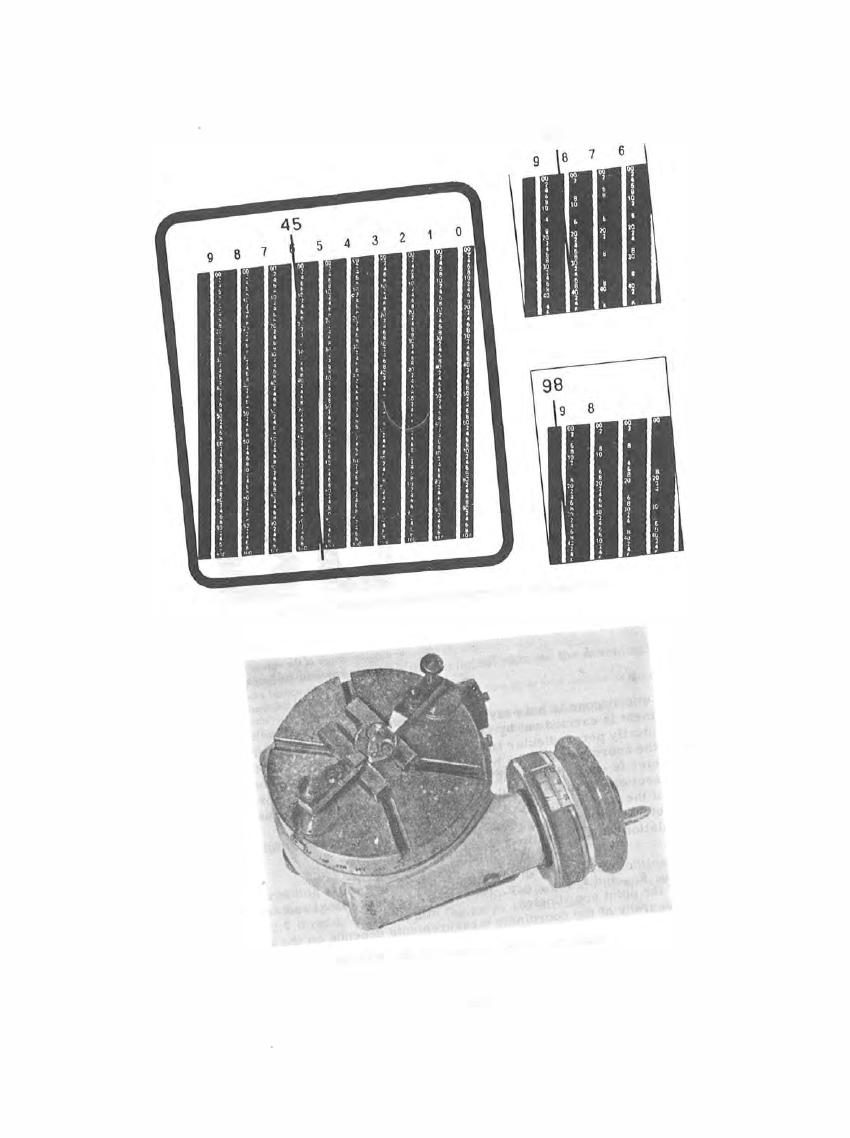
FIGURE 

59. 

Reticules  of the  side  microscopes  of the  R-324  instrument 

FIGURE 

60 .  

Circular  ,.ark  table  of the  R-324  instrument 

2 5'7 

• 

• 

• 

• 

• 

• 

• 

• 

10 

10 

• 

• 

• 

• 

[he  aiming  at the  center of  the  hole  whos e  position  is  to  be  measured 

call 

oe  realized by a  number of methods ,  depending upon the  micros cope 

des ign.  The  quickest and  most accurate  is  the  method of sup e rimposed 

images,  as  provided by a  s uperimposed- image  head;  the  noncoincidence  of 

the  optical  axis  of the micros cope and  the  hole  axis  leads  to  the  appearanc e 

of  two  identical  hol es  in  the  field  of  vis ion  of  the  microscope  (Figure  6 2 ,  a ) .  

The machine  slides  a r e  then displaced till  the  round  holes  coincide  and  the 
triangular images  becomE  s tar-shape d  ( Figure  6 2 ,  b ) .   In this  position  the 

optical  axis  of the  microscope and  the  hole axis  are  coincident.  The  highe r 

accuracy  of this  method 

i s  

due  to  the  elimination of the  influence  of  the  thick­

nes s  of the  reticule  marks  n : .d  to  the fact that a  shift x  of the  hole axis  re­

lative  to the optical  axis  of the micros cope p ro duces  a  shift  2x between  cor­

responding points  on the images . 

FIGURE  61 .  Fixing a point on the cir­

cular table  of the R-324 instrument 

,...  • 

• 

� 

FIGURE  62 .  Aiming the  microscope : 

a- noncoincidence  of the  optical  axis 

of the micro>cope lvith the hole axis; 
b-coincidence  of the optical axis of 

the microscope with the hole axis. 

If  the  microscope is  not  p rovided  with  a  superimposed-image  head,  the 

m easurem ent  is  carried  out  by  aiming the  c ross  hairs  at  the  intersections 
of two mutually perpendicular lines  with  the  hole p eriphery,  and  then  cal ­

culating the  coordinates o f  the hole  center (as s uming that  each  coordinate 
of the  center is  equal  to half  the  sum  of the  coordinates  of the  correspond­

ing intersections  of  the line with  the hole ) .   This  m ethod i s  frequently us ed, 

in spite of the larger amount of work involved. 

The  determination of the  actual  values  of the  coordinates  is  followed by 

the  calculation of the  deviations 

(Llx;  Lly) 

.1x = x  

- x  

nom 

act 

whe re 

X 110m  Ynom

and 

X act 

Y

act

are,  respectively,  the  nominal  and  actual 

values  of the  point  coordinates . 

The  accuracy of the  coordinate  measurem ents  depends  on the  accuracy 

of the  machine,  the  pos itioning and  the  reading.  When a  doubl e -image 

2 5 8  

method  is  used with  one  of  the  above - m entioned  machine s ,   the  meas urement 

error  does  not  exceed  2 [! .  

T

h

read  Tapping 

Watch  plates  have  s everal  threaded holes ,  us ed  for  s crewing  the  watch 

movem ent  to the  cas e ,   the  dial  to  the  plate  and ,  in  some m odels,  the bridges 
to  the plate. 

Threads  are  usually  tapped at  the  last machining operations  in  order to 

prevent clogging of the  threaded  holes  during intermediate  operations .  The 

machine  us ed for threading is  the  R - 6 4 ,   whose design  is  similar  to  that  of 

the  S - 3 1VI  d rilling machine  the  only differenc e  being that  the  spindle of the 
R- 54  machine  is  provided with a  friction  coupling by  m eans  of which it  can 

be  rotated in both  the  clockwis e  and  the  anticlockwis e  s ens e .   Threads  of 

0 . 3 - 1 . 5 mm  diameter can  be  tapped  on  this  machine .  The  spindle  rotates 

at  2 5 00  rpm during tapping and  at  3 6 0 0  rpm  for uns crewing the  tap,  the 

resulting cutting  speed  is  between  2 . 5  and  1 2 . 5  m / min. 

A  table  of cutting speeds  for tapping threads  in  LS6 3 - 3  b ras s  and for 

chas ing threads  in  U 7A V  s teel is  given  in Appendix  5 .  

The  threading  (basic )  tim e  i s  determined  from  the formula 

thr -

S•fl-p  ' 

where 

tap  travel,  mm; 

s  = 

thread pitch,  mm; 

n P  = 

spindle  rpm .  

The  idle  (or the uns crewing) tim e  is 

where 

nP 

and 

n i 

a re  taken  from  the  technical  data  on  the  machine . 

Example, 

Let  it  be  required to calculate  the  machining  time  on  an 

R-54 

machine  for  threading  a  hole 

of 0.7 mm  diameter in a  plate. 

The  tap travel is 

=  3.2 mm;  s  =  0 .175 mm  according to the thread standard ; 

np 

=  2500 rpm, 

3600  rpm,  according to the  technical  data on the  machine;  whence 

3 · 2  

Tthr= 

2500 ·0,1 75  = 0,007 

min 

2500 

T. 

3600 

0,005 

mm; 

tlu 

T,

nach= 

�hr 

Ti 

= 0,007 

0,005 

0,0) 2 

min. 

The  threading allowance  in the plate is  2 0  to  30 o/o  of the nominal  thread 

diameter:  the  tap  drill  diameter  is  0 . 4  mm for  an lVI  0 . 5  thread,  0 . 5 5  mm 

for an  lVI  0. 7  thread,  and  0. 70 mm  for an  M  1 . 0  threa d .  

2 5 9  

MARKING  AND  DECORATIVE  TEXTURING (CHASING) 

Figures ,  ins criptions  and  trademarks  are  applied  on watch bridges 

(

Fig­

ure  6 3 )  either by engraving by means  of a  pantograph or another  machine, 

FIGURE  63.  Engraved symbols 
on the train bridge of " Pobeda" 

watches 

or  by  embossing by  m eans  of  a  die .   Embossing 

is  the  more  rapid  m ethod but the  edges  of  em­

bos sed  s igns  or figures  are blurred,  and in 

addition,  parts  of weak  cross  s ection  are  de­
formed  during  embossing.  A  simple pantograph 

is  used for  making ins criptions  in  small-series 
production,  while in mass production the 

s-

50 

machine  desc ribed  earlier and the  S- 2 1 0  rna­

chine are  us ed.  Fixed  inscriptions  and  s igns 

are  automatically engraved in the  S- 5 0  machine. 
The S - 2 1  0 machine 

(

Figure 6 4 )  is more versatile ,  

and  is  capable  of engraving both fixed and  vary­

ing symbols  on flat and  cylindrical  surfaces . 

The  machine  has  five  high- speed spindles  with  engraving tools  m ounted 

at the  lower  end.  The  spindles  are in  the  front part of the m achine .   The 

spindle  block is  fastened to  the  machine  base  and  the  work table is  fed  in 

the  horizontal  plane. 

The  engraving tools  engage  the  work when the  spindles  are lowered.  A 

master and  a  s tylus  are placed below the  table .   The  inscriptions  engraved 

on the parts  are  reduced in size at  a  s cale  of between  1 : 5  and  1 : 5 0  relative 

to  those on the master.  The stylus  is placed m anually along the master 

groove .  The  dimensions  of the  master field are fixed  and  the  lever arms 

are  varied for setting the  reduction s cale .   The  engraving tools  plunge  into 

the  work automatically when the  stylus  has  been lowered into  the  master 

groove and leave  the  parts after the stylus  is lifted from  the m as ter. 

Fixed signs,  figures  and letters  are engraved  simultaneously on five 

parts ,  while varying  symbols  are  engraved  cons ecutively.  Let it  thus 

be  required to  engrave  on five parts  the  s equence of numbers  2 1 2 5 3,  2 1 2 54 ,  

2 1 2 5 5 ,   2 1 2 5 6 ,   2 1 2 5 7 .   The  first four figures  2 1 2 5  are  fixed and the last 

figure - 3,  4 ,   5 ,   6,  7 - is  varying.  The fixed figures  are simultaneously 

engraved on the  five parts ,  while  the  last  figure  is  engraved  cons ecutively 

using a  seven-figure  template  changer  which  replaces  the  master. 

Technical data,  S-210 engraver 

Number of spindles 

• 

•  .  •  .  .  .  . 

.  . 

. . . 

.  .  .  .  •  . 

Number of parts machined simultaneously 

• 

.  .  .  .  .  •  . 

.  . 

Spindle rpm 

• 

• 

.  .  .  .  15,000 

Maximum cutting tool diameter,  mm 

.  .  •  .  • 

. .  .  .  . 

2 .5 

Maximum cutting depth,  mm 

.  . .  .  .  .  .  .  .  .  .  .  .  . .  . 

Maximum field of the  master,  mm 

.  .  .  . .  .  .  . .  .  .  .  170 

65 

Copying  scales 

.  .  .  .  .  .  •  .  .  .  .  .  .  .  .  .  .  .  .  •  • 

From 1 : 5  to 1 : 50 

Maximum dimensions of the  machined part 

( diameter 

height),  mm  .

. .

.

.

. .

.

. .

.

.

.

.

.

.

. .

.

.  60 X 6 0  

Approximate production rate,  pieces/ shift 

• 

.  .  .  . .  . .  .  .  2 ,500 

2 6 0  


Content   ..  63  64  65  66   ..