Technology of watch production - part 63
rotated by guide pin (4 ) and a helical flute and assumes pos ition ll . Pushe r ( 3 ),
p ressing on the pins ( 5 ), forces plate ( 6 ) to the right and removes the
part from the s etting pins . A fter the next part has been placed on the pins
by the operator, the clamping pad ( 7 ) is retu rned from position II to posi
tion I by rotating the handle in the direction of arrow B. The part is thus
pressed onto the setting plate . The rack shaft and the clamping pad are
moved somewhat to the right by a spring, and s o allow the carriage to be
lowered into working position.
Cam
Spindle-
feed cam
Carriage-
lift cam
Stud-disk
indexing
cam
Barrel-
indexing
cam
Barrel -
lock pin
cam
Safety
cam
0
30
90
IZO
ISO
780 210 2'10
270 300 330
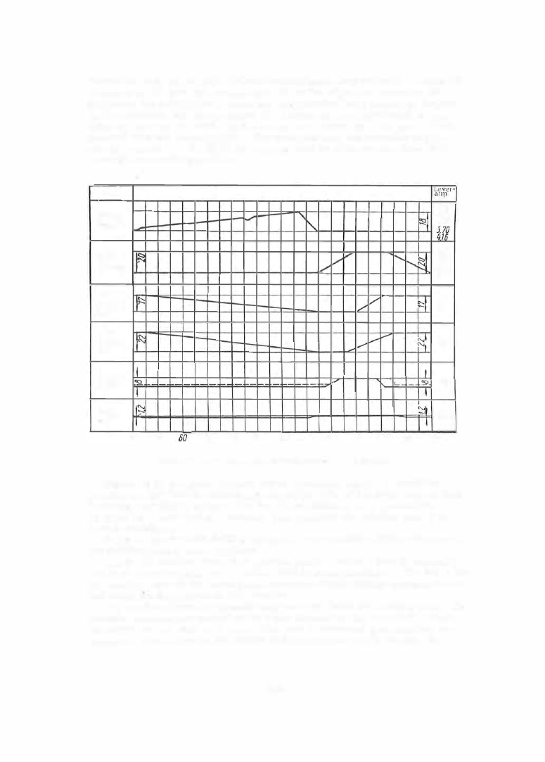
FIGURE 49. Cycle diagram for the S-44A machine-camshaft cams
ratlo
'2,34
2.80
3,26
0.25
0.32
0.38
0.5
QU
084
OZ7
3150'
Figure 49 is the cycle diagram for the camshaft cam s . It s hould be
pointed out that the idle movements cons titute 4 7 o/o of the cycle tim e in this
machine , and that in spite of this fact the machine is very p roductive:
56 holes can be d rilled in 1 minute . One operator can s e rvice from 4 to
5 such machines .
S- 2 1 2 s emiautomatic drilling machine.
This machine (Figure 5 0 ) se rves
for drilling lateral holes in plates .
The S - 2 1 2 m achine has a two -position plate in which a p art is manually
set on the locating pins while anothe r part is being m achined. The holes for
the winding stem in the watch plate are successively cente r - marked, d rilled
and bored by three tools on this m achine .
The machined part is automatically removed from the locating pins . The
machine motions are c ontrolled by cams mounted on the camshaft, which
can rotate at 5 . 1 , 6 . 4 , or
8
rpm . One part is machined per camshaft re
volution. The maximum dim ension of the machined p art is 45 mm, the
249