Technology of watch production - part 62
 

  Index      Books     Technology of watch production (Tarasov) 1964 year


Search            


Content   ..  60  61  62  63   ..


Technology of watch production - part 62


barrel slot and  the  indexing  cam  B  indexes  the  barrel by  1 / 1 0  revolution 

through leve rs  ( 2 ) and 

(3 

).  The  lockpin  engages  the  next  slot  on the  barrel . 

Both levers  are  returned  to  their initial  positions  by  springs . 

Part positioning and ejecting 

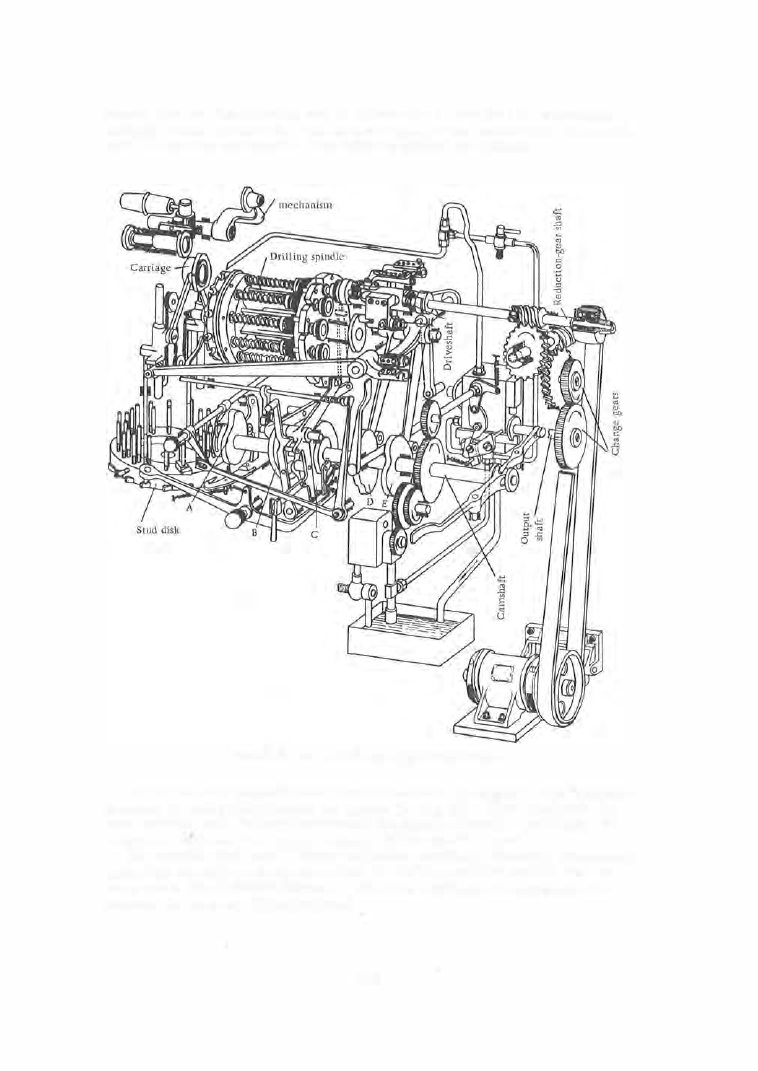
FIGURE 39.  Kinematic diagram of the S-44A machine 

At  the  end  of a  complete  cam  revolution lever 

( 3 )  

(Figure  42 )  re- engages 

the pawl  (4 )  and pulls  it out  of the  groove in  ring  (6 ).  This  interrupts  the 

cam  rotation until  the  next  indexing of the  spindle  barrel .  The  handle  ( 4 )  

(Figure  4 1 )  serves  for manual  rotation o f  the  spindle barrel . 

The  spindle-feed  cam D (Figure 4 3 )  and the carriage-lift cam E  (Figure 44 )

operating through lever systems ,feed  the  drilling spindle  and  lift  the  car­

riage when the stud disk indexes .  The lever  systems  are  equipped with 

devices  for  feed and lift adjustm ent. 

2 4 5  

A t  the  end  of  the  m achining cycle  the  lever  ( 1 )  (Figure 

4 4 )  

rotates  shaft 

(2 )  under  the  action of  a plunger,  and  lifts  the  carriage  into  loading position .  

The  device fo r  automatically  s topping the  camshaft a t  the  end  of the m a ­

chining cycle i s  shown i n  Figure 

4 5 .  

The  driving gear  ( 1 )  powers  the  cam ­

s haft  (2 )  through  the  key  ( 3  

)

The  camshaft is  s witched  off  automatically 

at the  end  of the machining cycle by  the  s top 

(4 ) 

on the  s tud  disk engaging 

the  catch 

( 5 ) .  

FIGURE 

40. 

Stud-disk indexing mechanism 

FIGURE 

42. 

Actuation mechanism for cams B and 

2 4 6  

FIGURE 

41 . 

Spindle-barrel indexing 

mechanism 

FIGURE 

43, 

Drilling spindle feed 

mechanism 

The  s tud  dis k  (see  Figure  4 0 )  positions  the  part  definitely  relative  to 

the  drilling-axis  spindl e .  The  disk  has  threaded  holes  located along two 

concentric  circles  into  which  are  s c rewed  hardened s tuds .  The  number of 
holes  on  each  circle is  equal  to  the  number of holes  to  be  machined.  The 

s tuds  support the  carriage  posts .  The  height of  each  pair  of  diam etrically 
opposed s tuds  determines  the pos ition  of  the  carriage  relative  to  the  spindle 

axis .  Stops  for  automatically  s topping the  cams haft  at  the  end  of the  ma­
chining cycle  are  mounted  on two studs .  The disk makes one  revolution 

during the  machining cycl e .  

FIGURE 44.  Carriage-lifting mechanism i n  loading position 

FIGURE 45 .  Automatic camshaft-stopping device 

2 4 7  

Ten  identical  drilling spindles  are  mounted in  the  spindle  barrel.  At 

the back end of each spindle  ( 3 )  (Figure  4 6 )  is  mounted  a  bushing  ( 1 )  with 

a  graduated  threaded  ring  (2 ),  which transmits  rotation to  the  spindl e  from 

the  driveshaft  friction  clutclo and  permits  the drilling depth  to be  adjusted 

to  an accuracy  of  0 . 0 1  m m .  

FIG URE 

4 6 .  

Drilling spindle 

The  ca rriage -motion  mechanism  is  s hown in Figure  4 7 .   The  carriage 

( 1 )  

is  rigidly fixed  to  the  right- hand lever  (2 )  and  articulatedly hinged  to  the 

l eft- hand  lever  ( 3 ) .   The other ends  o f  the  two  levers  have  articulated  c on­

nections  with  slides  (4 )  and  ( 5  ) .   The slides  move  on columns .  C arriage 

posts  (6 )  are  mounted in  the  slides  and  they  engage  the  s tuds  on the  s tud 

disk under the  weight  of  the  whole  carriage  system  and  the  tension of  spring 

(7 ).  The  left- hand post  rests  on the  outer s tud ,  and  the  right- hand post 

engages  the inner  s tud.  By  varying the height  of the studs  the  motion of  the 

carriage  in  the  xy  plane  is  controlled. 

FIGURE 

47. 

Carriage- motion  me­

chanism 

FIGURE 

48 .  Device for  clamping  and ejecting the part 

The  device  for  ejecting  the  machined part and  mounting the  next  part on 

the  holding plate  is  s hown  in  Figure  4 8 .   If  the  handle i s  rotated i n  the  dire c ­

tion o f  arrow A ,   the  rack s haft  ( 1 ),  the  rack 

(2 ) 

and the pusher ( 3 ) are fas ten ­

ed  to  the  right.  The  rack shaft,  in  moving to  the  right,  is  s imultaneously 

2 4 8  


Content   ..  60  61  62  63   ..