Technology of watch production - part 60
 

  Index      Books     Technology of watch production (Tarasov) 1964 year


Search            


Content   ..  58  59  60  61   ..


Technology of watch production - part 60


.. 

.. 

(�K��)v 

·� 

.. 

' .... 

... 

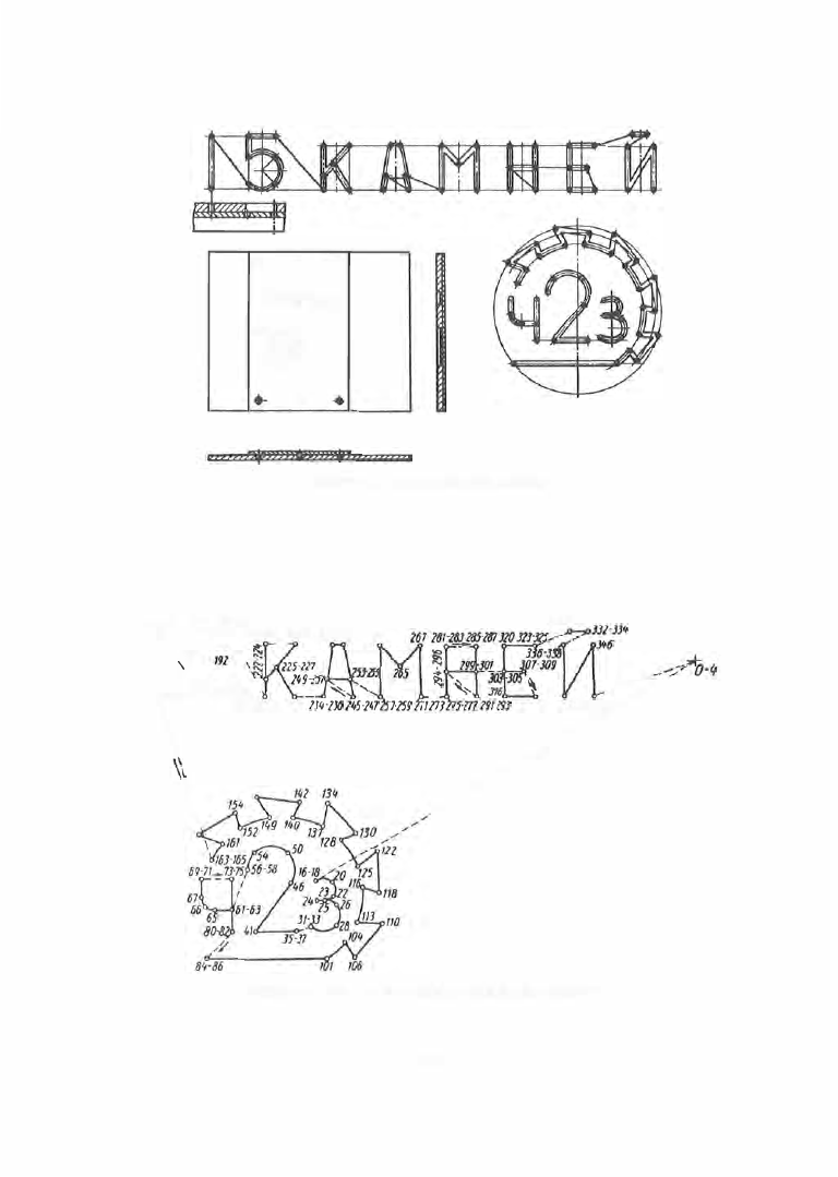
FIGURE  29.  Master for the F-121 machine 

t79-M1 

198 

l(Jt-lOJ 

Jl8-JJO 

t � 

lll·ll't.JI6.ZI8 

l40W  l6J 

,  ,  -

195 

(X 

\  -186 

-� ..... 

!71·174 

189 

-

- .......... 

l06-l08lJO-lJl 

J/1-JJJ.  Jvl  J50-J5j ....-

.......... 

..... ..... 

..... � 

..... ..... 

� 

..... ..... 

.......... 

..... ..... 

!58 

FIGURE  30.  Cutter  path  for  marking the cams for the 

S-50 

machine 

2 3 7  

For marking the  cam s ,   center punches  are  mounted  in  the  spindle  c ollets . 

The  pin at  the  end  of  arm  ( 1 )  enters  the  slot  on the  master ( 4 )  and  moves 

along the  path .  The  right-hand  index plate is rotated to the required angle 

(equal  to  the path  s ector )  by  means  of  the handwheel  ( 1 2 ).  The  plate  ro­

tates arm  (2 ) and table  (5 ) by means  of rod  ( 8 )  and  lever 9 .   Simultaneously, 

it rotates  the left- hand plate through the  same  angle  by means  of  rod  ( 1 0  ). 

Rod  ( 8 )  on the left plate  is  in  this  case  disconnected from  arm  ( 1  ),  and  the 

pin on the  end  of the  latter is  free  to move  in the  master slot. 

The spindle  c enter punches  copy the pin paths  on the blanks  to a  s cale 

of  1 : 3 .   Depending o n  the path profile,  the  index plates  are  c onnected by 

rod  (8 )  either with arm  ( 1 )  or  with  arm  (2 ).  After the  marking the  cams 

are  rough-machined using general - purpose equipment,  and are then pos i ­

tioned anew i n  the  F - 1 2 1  m achine .  The  center punches i n  the  spindles  are 

replaced successively by an  end-milling  cutter and  a  mandrel with a  grind­

ing  disk. 

The  master for the F - 1 2 1  machine  along  with the form  to be marked is 

shown in Figure  29,  while  Figure  3 0  gives  the cutter path for markin g the 

profile  of the  cams  for  the  S - 50 machine . 

The  F - 1 2 1  m achine  reduces  to  a  half  or  a  third  the  work entailed  in the 

m anufacture  of the  cams  and  eliminates  the  rotation - angle  errc 

in the  cam 

p rofile . 

Figure  3 1  shows  the  tool used in  the  S - 5 0  machine:  a)  single -lip  cutter, 

b)  collet for gripping the cutter. 

Tl'le  S - 1 8 7  s emiautomatic  two - spindle  contour-milling machine  (Figure 3 2 ), 

functions  in  a  manner s imilar  to  that  of  the  S - 5 0  machine  and  is  produced 

by the Soviet industry.  Its p roduction rate is  almost twice  that of the S - 50 

machine,  because  of its  twin  spindles;  but on the other hand  it requires a 

much  fine r  adjustment to  ensure  identical  contours  on  the  two  s imultaneous ­

ly machined parts .  In  contrast  with  the  S - 5 0  machine ,   part  and  tool  move 

along Cartesian  coordinates  in  this  m achin e .   The  machine  s lide  ( 1 )  (Figure 

33 ),  together with the two parts fastened to  it,  is m oved  vertically by means 

of  a  rack  and 

gear  segment.  The  bed  (2 )  carrying  the  tool  spindles 

moves  in a  horizontal plane:  longitudinally for milling- depth  control (by 

stops ),  and laterally  for  p rofile  cutting.  The  method  of  cam  calculation  is 
based  on the  cutter path  and  on the  analytical  or  graphical - analytical  meas ­
urem ent  of  the  point coordinates . 

FIGURE  31 .  Tools for the S-50 machine : 

a-cutter;  b-cutter collet. 

2 3 8  

<..:> 

CD 

FIGURE  32.  S-187 semiautomatic two­

spindle milling machine 

FIGURE  33.  Kinematic  diagram of the S-187 semiautomatic two-spindle milling 
machine 

Technical data,  S-187 machine 

Number of parts machined simultaneously  . .  

Maximum machining surface ,  mm  . . . .  

.

.

 . 

Maximum thickness  of parts,  mm 

.

.

.

.

.

.

.


Maximum cutter diameter,  mm 

.

.

.

.

.

.

.

.


Spindle speed,  rpm 

.

.

.

.

.

.

.

.

.

.

.

.

.

.

.

.


Time for  one working cycle,  sec  . . . . . . .  

Electric motors : 

tool 

.

.

.

.

.

.

.

.

.

.

.

.

.

.

.

.

.

.

.

.

.

.


camshaft 

45 

45 

14 

7400 

From 10 to 125 

0.65 kw , 

2895 rpm 

0.4 kw, 

1400 

rpm 

Inspection of  Milling and  Turning Ope rations 

The  facing,  boring,  and  milling of  recesses  in  plates  and  cocks  are  fol ­

lowed by  inspection  of  the  depth  of  the  reces s es  and  of  the  contour pos ition 

relative  to  the working holes .  This  inspection is  carried out us ing  either 
a  comparator or a  special  gage . 

The  depth  of  counterbores  is  m easured  using a  vertical  dial  gage  o r  a 

vertical micrometer  (Figure  34 ) .   The  use  of  a  dial  gage,  with  s cale  divi­

sions  of  0 . 0 1  m m ,   is less  tim e - consuming.  The quality of the  surfaces 

machined on the S - 8 1A  and S - 5 0A  machines  is  inspected with the help  of 

magnifying  glasses with a magnification  of 5X,  1 6X,  or,  rarely,  32X. 

FIGURE  34.  Vertical micrometer 

2 4 0  


Content   ..  58  59  60  61   ..