Technology of watch production - part 61
 

  Index      Books     Technology of watch production (Tarasov) 1964 year


Search            


Content   ..  59  60  61  62   ..


Technology of watch production - part 61


T H E   M A C H IN ING  OF  HOLES 

The  machining of  holes in plates  and  cocks  is  a  c omplex and  crucial 

operation.  The  diameter  tolerance in most cases  is  0 . 005 mm;  the  s urface­

finish  quality  corresponds to class 9 - 1 0  at least;  and the interaxial- distance 
tole rance  is  0 . 0 0 7 5 - 0 . 0 1 0  m m .  

These s evere  requirements  are  satisfied by  s ubj ecting the  holes  t o  pre­

liminary and  final  m achining stages . 

The  preliminary  machining consists  either in  center  marking followed 

by punch piercing,  cente r  marking followed by drilling,  or punch piercing 

without  cente r  marking. 

The final  m achining  consists  in shaving the holes  in  special  dies .  Ream ­

ing  has  found  no  application  in  the  final  machining of  hole s ,   as  it  is  both  a 

less  accurate  and  a  less  productive  p rocess  than  s having.  Some holes  are 

threaded. 

Drilling 

The  watch  indus try and m any  other branches  of the  p recision- ins trum ent 

industry  make  extensive  use  of the  method of  drilling holes  according to 

center-punch marks ,  this  method being s uperior to  the  method of  drilling 

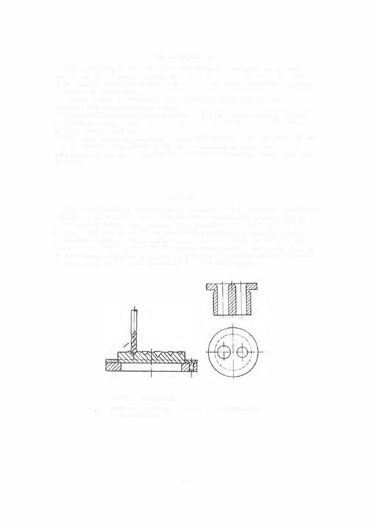
in  jigs .  The  part  to  be  drilled lies  freely  on the  drilling-machine  table  o r  

o n  a n  open  support,  and i s  easily placed manually under  the  drill  (Figure 

3 5 ,   a ) .   The  drill  is  guided by  the  center-punch  m ark.  The  use  of  jigs ,  on 

the other hand ,  requires  considerable  time  for  the  positioning and  fastening 

of the  part  in  the  jig,  and  removal  of the part  afte r  drilling. 

�) 

b) 

FIG URE 

35 . 

Drilling holes : 

a-according to center-punch marks;  b-jig bushing  for drilling 
closely spaced holes . 

2 4 1 

If  only  two  or  three  holes  are  drilled using a  jig,  the auxiliary time may 

turn  out to be longer  than  the d rilling  (basic )  time .  When a large  number 

of holes  are drilled in the same part,  it may  happen that not all  the  holes 

can be  drilled through  in  one  setting,  and  the part has  to be repositioned  in 

the  jig.  An  especially  complex bushing is necessary for drilling clos ely 

spaced  holes  (Figure  3 5 ,  b ).  Jig drilling is  less  accurate  s ince a  d rilling 

e rror,  in  addition  to  the  jig inaccuracy,  results  from  the  clearance between 

the  drill and the jig-bushing hol e .  

The  accuracy o f  the  distance  between  centers  i s  improved b y  d rilling 

according to  center-punch  marks . 

If  the  number of  holes  is  s mall,  they are  drilled on  the  S - 3M  (Figure  36 ) 

or  S- 1 2 M  (Figure 

3 7 )  

bench- type  vertical  drilling machines . 

FIGURE 36 .  S -3M single-spindle drilling machine 

FIGURE  37 .  S-12M double-spindle drilling machine 

242 

For a  large numbe r  of holes  the S- 44A  semiautomatic  machine  is  us ed. 

The  s econd spindle in the  S- 1 2 M  machine  is  frequently used for  countersink­
ing the  holes  drilled by the  first spindl e .  

Holes  in brass ,   o f  diameters  from  0 . 2  t o  2 . 0 mm ,   can be  drilled on the 

S - 3 M  and  S- 1 2 M  m achine s .   The  spindle  speeds  of these machines  are 

6 000 and  7 5 00  rpm ,   respectively. 

The  production rate  of the  drilling machine  depends  on the  mechanical 

prop e rties  of the  metal,  the  hole  diam eter,  and  the  spindle  rpm . 

The  mechanical  strength  of drills  0 . 2  to  0 .  7 mm  in  diameter  is  poor and 

therefore  the  drill  must be  withdrawn  from  the  work  from  tim e  to  time  dur­

ing drilling for chip removal  (Table  5 ) .  

The  cutting conditions f o r  drilling LS6 3 - 3  bras s  a t  

n  = 

6 0 00  rpm  are 

given in  Table  6 .  

TABLE  5 

Number of drill withdrawals as  a  function  of the diameter and  depth,  mm 

Drill dia-

Drilling depth 

meter 

0.8 

1 .1 

1 .4 

1 .7 

2 .3 

2.5 

Number of drill withdrawals 

0 .2 

0 .3 

-

0.5 

-

-

-

0.7 

-

-

-

-

-

The  drilling (basic )  time  is  determined by: 

where 

11  = 

the  drilling  depth,  mm; 

/2 

the  drill  approach,  mm; 

sm = 

feed,  m m / min,  from  Table  6; 

with  l2 being taken from 

where 

q>  = 

half the  drill-point angle; 

2.9 

3 .2 

The  holes  are  als o  countersunk  on  the  S- 3 M  and S- 1 2 M  machines . 

TABLE  6 

Speeds 

m/min.  and  feeds s.  mm/min.  as a  function  of the  diameter D. mm, 

for drilling LS-63-3 brass 

• m  

• m  

tl 

•m 

s m 

0 .2 

36 

3 .75 

0.6 

1 50 

11 .30 

1 . 0 

280 

18 .84 

1 .3 

350 

24.50 

0.3 

48 

5 .65 

0.7 

186 

13.20 

1 .1 

31 0 

20.70 

1 .4 

383 

26.40 

0.4 

78 

7 .54 

0.8 

227 

15.1 

1 .2 

330 

22.60 

1 .5 

395 

28 .40 

0 .5 

114 

9 .40 

0.9 

250 

1 7 . 1 0  

2 4 3  

The  S - 44A  ten- spindle  s emiautomatic  drilling  machine 

is  us ed in watch 

p roduction  for  drilling and  countersinking holes  in plates  and  bridges .  The 

m achine  cons ecutively pos itions  the  axes  of the  holes  to  be  machined op ­

posite  the  drilling- spindle axes  (Figure 

3 8 ) . 

The  machine  can  drill  consecutively,  in  one  chucking,  from  2 0  to  5 0  

holes  o f  ten different  diameters  with any  location  of the  holes  on the part 

FIGURE 38 .  S-44A  semiautomatic drilling 

within the  limits  of  a  circle  of  46  mm  dia­

meter.  The  cutting tools  use d  are twist 

drill s ,   pointed d rills  and countersinks , 

held  in  the  spindle  collets .  The  center­

punched part  is  positioned  on a pin plate 

on the  carriage.  The  carriage  moves  in 

a  vertical plane  and  positions  the  center ­

punched  hol e s  i n  front of the  drills .  

A fter all  the  holes  having the  same 

diameter have been  drilled,  the  spindle 

barrel  is  indexed  1 / 1 0  revolution,  and 

the  next  spindle ,   with a  drill  of  different 

diameter,  is  fed  into  working position. 

The machine is  automatically s witched­
off after all the  holes  have been drilled, 

and the  work carriage  is  lifted to the 

loading position for  reloading.  The part 

is  loaded and  removed manually. 

The  kinematic  diagram  of the m achine 

is  s hown in  Figure 

3 9 .  

The  electric  mo­

tor powers  the  reduction- gear s haft, which, 

in turn,  drives  the spindle  s haft  through 

a  claw clutch.  The  spindle  shaft powers , 

through  a  friction clutch,  the  d rilling 

spindle which is  in working position. 

Power is  transmitted to the reduction-

machine 

gear  output  shaft through  two  worm- and­

wheel  s ets  and a  pair of s pur change  gears .  The  output shaft powers  the 

camshaft through  a  pair  of  fixed  gears .  Six  camshaft speeds  are achieved 

by  changing the change  gears . 

The  camshaft carries  the  following cam s :   s tud - disk indexing (A ),  barrel 

indexing  and locking  (B and C ),  spindle  feed  (D) and carriage lift  ( E ) .  

The  s tud- disk indexing c a m  A  is  s e t  on the  front end of the  camshaft 

(Figure  40 ).  By acting  on lever  ( 1 )  and s lide  (2 )  the  cam  displaces  the 

pawl 

( 3 )  

to  the  right  and  thus  indexes  the  s tud  disk by  one  tooth  on the  rat­

chet wheel .  The  s lide  and pawl  are  returned  to  their initial pos ition by  the 

spring  (4 ) .  

The  barrel -indexing cam  B  and  the barrel -locking cam  C  are fastened 

on a  common bushing freely mounted  on the  camshaft  ( Figure  41 ) .   They 
are  controlled by the  s top  s c rews  ( 1 )  on the  s tud  disk  (Figure  42 ) .  

When  the  s tud  dis k  is  indexed b y  one  tooth,  s top  s crew  ( 1 )  engages  the 

toe  (2 )  and lifts  lever 

( 3 ) . 

The  right-hand  arm  of the  l ever  d rops  and  frees 

the pawl  (4),  which engages,  under the influence  of the spring  ( 5 ),  a  groove 

in  ring  ( 6  )

fastened  rigidly to  the  camshaft.  Both  cams  B  and  C  begin  to 

rotate .  The  l ocking cam  C  pulls  the l ockpin  ( 1 )  (Figure  4 1 )  out  of  the 

244 


Content   ..  59  60  61  62   ..