Technology of watch production - part 58
 

  Index      Books     Technology of watch production (Tarasov) 1964 year


Search            


Content   ..  56  57  58  59   ..


Technology of watch production - part 58


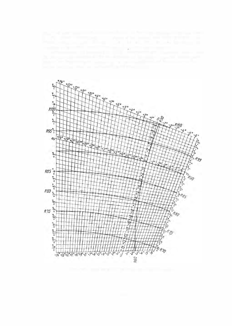
o rigin  of  c o o rdinates  on  the  n etwork  lies  at  the  inters ection  of  the  two  arcs 

90, 

which  correspond  to  the  paths  of  the  c utte r  and  table  c en t e rs .  A d ­

ditional  a rc s ,   o r  radii 

7 0 ,   7 5 ,   80,  8 5 ,   9 0,  9 5 ,   1 00 

from  the  c ente r  of 

rotation  of  the  tabl e  l e ver  have  been  d raytn  for  convenie nc e .  

Determination  o f  the  number o f  idle-movement  cam  degrees . 

A s   a  rul e ,  

the  l a rges t  idl e  m o vem ent  i s   the  a d vance  o f  the  cutter  from its  initial  p o s i ­

t i o n  to  t h e  beginning  of  m achining,  o r  t h e   withd rawal  o f  t h e   cutter  to  the 
initial  p o s i tion  after  the  term ination  o f  m ac hining . 

-

.. 

so 

R 70 

..., 

FIGUI<E 

24. 

Degree 

net1vork  for 

figuring 

the  cams of the  S - 5 0  machine 

2 2 9  

The  o rd e r   of  determination  of  the  cam - rotation  angl e s   is  as  fol l o ws . 

First,  the  angles  of  the  two  l e vers  in  the  initial  pos ition  relative  to  the  o r ­
igin  of  c oordinates  are  determined  on t h e   network.  The  angl e s   obtained 
are  c onverted  (using  the  tabl e  (A ppendix 

4 ) ) 

into  the  radial  increm ents 

6.R . 

The  angular  pos itions  of  the  two  l e vers  for  the  plunging  point 

are  then 

determined  (Figure  2 5 ),  and  their  values  s imilarly  c onverted  into  radial 

increments 

6.R. 

The  al gebraic  difference  between  the  increm ents  repres ents 

the  value  of  the  ris e   for  each  cam .  The  cutt e r  advance  results  from the  two 
m otions  (cutter  l ev e r  and  t able  l e ve r ) ,   and  the  cam  angl e  will  be  the  s a m e  
for  both  cam s . 

The  cam  angles  corresp onding  to  the  other  idle  m o vements  are  d e t e r ­

m i n e d  i n  t h e   s a m e   way .  

Dwells  of 

to  2 °   must b e   s chedul e d   at t h e  e n d  of  each  ris e  o r   d rop  i n  

o r d e r  t o   ensure  a  s m ooth  transitio n .   A  dwell of 

t o  

6 °  

i s   s chedul ed  aft e r  

t h e   cutter  retracts  t o  i t s   initial  pos ition  for  the  autom a·iic  s witching o f f  o f  
the  machin e .  

tJj]f 

!JR =2L 

sin¥ 

or 

f. 

or 

lld' 

where 

the lever  arm 

FIGURE 

25.  Setu!' calculation for the S-50 machine : 

a- angles of rotation of the lever;  b- increment of the cam  radius, 

t.R. 

Determination  of  the  number  of  cam  degrees  for  actual  machining. 

The 

numb e r  of  cam  degrees  per  path  p oint  (  or  the  p ath  l e ngth  in  mm  p e r   cam 

degre e )  i s   determin e d   by  s ub tracting  the  total  num b e r   of  i dl e - m ovem ent 
degrees  from 

3 6 0° 

and  dividing the  resul t  by  the  len gt h  of  the  a c tual  m a ­

chining  p ath  of  the  cutte r .   The  points  a r e  numbered  in  acco rdance  with  the 
co rresp onding  cam  angles .  In  s pl itting the  m achining p a th  into  s e ctors , 
the  following  conditions  must b e   obs e rved:  a  whole  numbe r   of  degrees  is 
appo rtioned  to  each  s e ctor  drawn  a c c o rding  to  the  same  law  (arc ,  s t raigh t  
line ) .   Each  arc - s hap ed  s ector  is  divided  into  a  num b e r   of p arts  e qual  to 
the  number  of  degrees  apportioned  to  i t ,   and  the  points  of  division  are  num ­
b e re d   accordingly.  F o r   s t raight  s ectors ,  only  the  initial  and  final  p oints 
are  num b e r e d .   If  arcs  of  s mall  radius ,  co rresponding  to  a  s e gm e nt  of 

to 

2 ° ,  

are  encoun te red  in  the  cutter  p ath,  it  is  n e c e s s ary  to  d e viate  from 

the  a c c ep t e d   design  values  and  to  add  to  the  number  of  c am  degrees  on  this 
arc  in  order  to  obtain  the  p rop e r   geometry  for  the  c ontour  to  b e   m illed  ( s e e  
points 

6 2  

to 

6 6  

i n   F igure 

2 3 ). 

2 3 0  

The  design number of  degrees  can  be  correspondingly  reduced  in  straight 

secto rs  (see points  8 5 - 8 7 ). 

In plunging  and  lifting,  the  cutter does  not move  along the  contour,  while 

the  camshaft  continues  to  revolve.  Thes e  points  are  acco rdingly numbe red 

(  . 

4  1 3  . 

2  ) 

y  two  num  ers  pomt 

1 2  

111 

F1gure  3  . 

The  values  of  the  angles  for  each point are  converted  according to  the 

table  (Appendix  4 )  into  inc rements 

D. R .  

The tabular values  are  calculated 

acc ording to  the  formula 

ll R = 2l · sln 

where 

=  the  lever a rm . 

The  curves  on  the  cams  are  A rchimedean  spirals . 

Analysis  of  the  accuracy  of  the  method  of  cam  figuring. 

Errors  are 

ine vitable in the  graphical  plotting of the  network  and in  the part  drawing .  

These  e rrors  will b e  transferred t o  the p roduct  togethe r  with the  errors  in 

cam  manufacture  and  the  errors  in  the  m achine  operation .  The  error in 
graphical  plotting  consists  of:  the  e rror in  graphically plotting the  cutter 

path to a  s cale  of  2 0: 1 

( A1 

=  0 . 02 mm),  the  error in  drawing the degree net­

work 

(A2 

=  0 . 02 mm ),  a  measuring error of  0° 1 '  on the network or corre­

spondingly  on the part 

( A3 

0 . 02 6  mm),  and  the  error  resulting from  the 

conve rsion  of the  angle  to 

D.R 

according to  the  table  in App endix 4 

( A4 

= 0 . 003 

m m ) .  

The  maximum  total  e rror o f  the  graphical  method i s  

EA 

=  0 .  0 7  m m .   The 

graphical  plotting and  the  m easurem ents  must accordingly be  done  very 

carefully. 

Determination  of  the  duration  of  the  machining  cycle. 

Duration of one 

m achining cycle  is  determined by  the  formula 

360° 

Tsec  = c;.o Top , 

whe re 

T0P 

=  the  time  during which the  cutter is  in  ope ration; 

a" =  the  s um  of idl e - movement cam  degrees; 

with 

-

60 · S  

o p   - m · b ·n ' 

where 

=  the  length  of  the  cutter machining path  (according to  the  drawing); 

m =  the s cale  2 0 : 1 ;  

= the  feed p e r  cutter revolution, ( 0 . 0 3 - 0 . 04 mm ); 

=  the  cutter rpm  ( 5 2 0 0 ),  and 

The  production  rate 

-

360°·60 

· S  

sec -

ao· m · b ·n  • 

6 0  

o f  the  machine i s  

=

-

T  = 

sec 

pieces / minute . 

Cam-figuring 

example 

for 

the 

milling of plates 

The  initial  position  of the  cutter,  in  machining the  " ldolniya"  brand  pocket-lv atch  plate  correspond;  to 

points 

350 - 351 

( Figure 

23). 

The  cutter  is  rapidly  advanced  through  the  sector 

351 -4 ,  

and  the  angle 

of 

ro­

tation  of  the  cam  is 

13'. 

The cutter  plunges  in sector 

4 - 6 

to the 

0 . 57  mm 

plane 

( 0 . 5 7  

m m  

is the  thicl<ness),  and  then  folloiVs  the 

2 3 1 

anticlochtise  circuit  6 - 1 2 .   From  point  12  to  point  13  the  cutter  moves  to  the  0.6 mnr  plane  (the  table 
drops  0.03 111111).  At  tlris  new  depth  it  moves  along  a  straight  line  to  point  1 6 .  

The  cutter  then  describes  a  circular  arc t o  31 ' .   Sectors  31 - 33 - 3 5  are  straight  lines and  serve  for 

by- passing  the  point  of contact  ben•een  the  two arcs.  The  sectors  35 - 46 - 48 - 5 0 - 5 5 - 5 6 - 62 - 66 -
72 - 7:1 - 75 - 77 - 7 9 - 82 - 85  are  milled at the same  0.6 

n1111 

depth.  The  intervals  between the  points  in 

sectors  6 - 1 � .  62 - 66  and 7 3 - 75 have  been  reduced  in  order  to  obtain  a  more  accurate  contour.  The cutter 

is  rapidly  advanced  along a  straight  line for the  idle  movement  in  the sector 8 5 - 8 7 ,   with a  simultaneous 

change  in the  m ill ing  depth to  the  0.7 mm  plane.  This  plane  is  machined  in sector 87 - 93  in  one  cutter 

pass (the  cutter  diameter  is  equal  to the  slot  width).  The  milling  depth changes  from  0.7  ro  0.9 

n1111 

in  sector 

9 3 - 95. 

The  0.9 mm  plane  is  machined on sectors  95 - 97 - 1 03 - 106- 109- 114 - 127- 1 2 9 - 140.  The cutter 

is  rapidly  advanced  in sector 140- 141  and  the  depth  is simultaneously  changed  for the 

J  .o:; 

1 1 1 1 1 1  

plane .  The 

rapid  advances  on sectors  85 - 87  and  140- 141  are  easily  made ,  as  no  metal  is  removed  in  these  places. 

The  1 .05 mm plane  is machined on sectors  1 4 1 - 146- 1 67 - 172 - 1 83 .   The  milling depth is changed on 

sector 183 - 184 to 1 .4 11lm.  The  plate  is  milled  at  this depth on sectors 1 84 - 1 8 8 - 1 98 - 2 0 0 - 204 - 2 1 0 -
212 - 21 9 - 249 - 254 - 260. 

The cutter  is rapidly  advanced  over  sectors � 6 0 - J61 - 263,  passing si multaneously  to the 1 .3 

n 1 1 n  

plane , 

after  '" hich i 

continues  on sectors  263- 27 5 - 277 - 281 - 285 - 289- 291 - 302 - 309- 311 .  Sector  3 1 3 -

3 2 5  i s  machined  on the 1 .5 n 1 1 n  plane ,  after which  the  cutter  leaves  the  plate a n d  moves ( above  the surface 

of the  component)  to  point  333.  lt  plunges  on  sector  333- 335 to  the  1 .15 mm  plane  and  continues  along 
sectors  :335- 336 - 338 - 339.  On sector 339- 341  of the  cam the cutter again  leaves the plate  and  returns 
on sectors 341 - 350 to  irs initial position.  The  time  taken  by  one  cycle  is  52  sec.  The  camshaft  revolves 

at speed  No.  2.  The  rotation  angles  for the  table  lever  and the  cutter  lever  are  determined  from  the  path 
diagram by  superposing  over  the  component' s  drawing the  degree  grid,  and  the  values  obtained  are  introduced 
into the  setup sheet for each  cam.  The  profiles of cams (21),  (22),  and (23)  are shm•n in  Figures 26  and  27 , 

and  the  calculation tables  are  given. 

Calculation  of the bell  cam 

(23).  The  maximum  milling depth ( 0 .57 mm  in Figure  23) corresponds to 

16 mm  cam height.  The  rise  or drop  on the  cam corresponds to a  rise  or  drop  of the  work  table  to  a  scale 

4 : 1 .   A 

change 

in 

the  milling  depth from 0 .57  to  0.6 mm 

thus 

corresponds  to  a  drop  of ( 0 .6 - 0.57) X 4  

0 .12 

on 

the 

cam.  The zero  point of the  bell cam (23) is  shifted  by  360

-

177" 

183" relative  to 

the  zero 

point 

of cam (22). 

Let us examine the transition  from  depth  0.57 mm  to  depth  0.6 mm.  This corresponds to  points  12"- 13" 

on  the cutter path.  The transition  must  begin not earlier than 12"  and  end  not later than 13".  The  correspond­
ing angle  on  the  bell  cam  is  1 96'  according  to  the  following calculation :  the  beginning  of the  transition  is 
taken  as  1 3  +  1 81" 

1 96 " ,   i . e .   w ith  a  delay  of 

1 " ,  

taken  as  allowance  for  cam  adjustment. 

FIGURE  26.  Profi le  of  earn (21) 

2 3 2  


Content   ..  56  57  58  59   ..