Technology of watch production - part 56
 

  Index      Books     Technology of watch production (Tarasov) 1964 year


Search            


Content   ..  54  55  56  57   ..


Technology of watch production - part 56


Concentric  recess es  are  als o  bored  on  the  S - 5 7 M  machine  whos e  design 

is  similar  to  that  of  the  S - 8 1A  machine .   The  two  machines  differ i n  the 

method  of  chucking  the  work.  In  the  S- 8 1A  machine  the  part is  gripped  on 
its  periphery  by  a  collet  chuck,  while  in  the  S - 5 7 M  machine it is  gripped 

by fingers  of a  jaw  chuck from  the machined  side .  Therefo re,  only on the 

S - 8 1A  machine  can  the  whole  face  surface  of a  part  be machined. 

The S- 5 7 M  machine  gives  a  more accurate boring depth,  the part fitting 

more  clos ely against the bearing surface. 

Both  types  of semiautomatic  machines  have  a  high  production  rate  and 

are  characterized by easy s e rvicing and  simple  adjustm ent . 

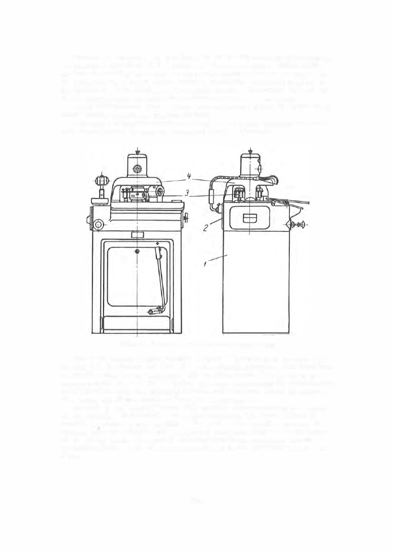
FIGURE 1 7 .   General view  of the  S- 188 rotary  shaping  machine 

The 

S- 1 8 8   rotary  shaping  machine 

(Figure  1 7 )  cons ists  of the  bas e  ( 1 ), 

the  bed  (2 ),  the  rotary tool  head  ( 3 ),  and  a  chucking fixture .   The base has 

a  s tarting p edal  on its  front  fac e .   The  working parts  of the  machine  are 

mounted  inside the  bed  (2 ):  the  drive,  the  cams  controlling the  chucking and 

ejection of the part,  the  chucking  fixture ,  and  the  lower  end  of the  spindle . 
The  upper end  of  the  spindle  is  fastened  in  housing  (4 )

The rotary tool head (2 ) (Figure 1 8  ),  on whose  circumference  are  mount­

ed five tools ( 3 ),  is  fastened on the  machine spindle ( 1 ).  Cams  (4 )  and  ( 5 )  

control  the  chucking and  ejection o f   the  part.  The  spindle  revolves  a t  

7 0 rpm ,   corresponding to a cutting speed o f  3 0 m / min a t  the  mean diam eter 

of the rotary head .  One part is  machined per head revolution,  and the 

machining (basic )  tim e  is  therefore  about  1  s ec;  the  auxiliary  time  is  1  to 
2  s e c .  

2 2 1  

The  part  is  pos itioned  manually  in  a  fixture  on  tab l e  

(6 )

and  e j e c t e d  

auto matically  by  rotating  l e ve r  

(7 ) . 

The  part  is  held  fixed  during  m ac hining. 

The  head  i s   s topped  by  cam 

( 8 ) .  

The  chips  a r e  blown  away b y  a i r ,   fed 

through  a  cam - c ontroll e d   valve . 

FIGURE  1 8 .  

Kinematic  diagram o f  

t h e  S-188  rotary  shaping  machine 

The  p a rt  to  be  m a c hined  i s   p r e s s e d  by  two  jaws 

( 1 )  

(Figu r e  

1 9 )  

a gains t 

s top  ( 2 )  a nd  platen 

(3 

) .   The  chucking j aws  are  fastened  to  l evers 

(4 

), 

whi ch 

a re  actuated  by  cam 

( 5 )  

when l ever 

( 7 )  

i s   rotate d .  

Ejection  i s   control l e d  b y  c am 

( 5 )  

(Figure 

1 8 )  

th rough  plunger 

( 6 ) .  

sloped  c hute  for  r e m o ving the  parts  i s  attached  t o  the  chucking fixtu r e . 

The  cycle  diagrams  f o r   the  m achine  cams  a r e   given  in  Figure 

2 0 .  

Idl e 

movements  c ons titute 

1 3  

o/o 

of  the  part  tim e . 

The  m ate rial  allowance ,   0 . 2  mm  p e r   s i d e ,   is  unifo rmly  dis tributed  am ong 

the  five  tool s .   The  m ac hine  p roduc es  a  class  9 

o r  

1 0  

surfa c e - finis h quality, 

while  the  p a rallelness  and  flatne s s   are  b e tween 

0. 005 

and 

0. 0 1 0  

m m   and 

depend  to  a  considerable  extent  on  the  pos itioning  and s ha rp e ning of the tool s .  
The  head  was  s o   d e s i gned  that  the  tool  pos ition  can  b e  adjusted  both  i n  the 
ve rtic al  direction  and  in  th e  plane,  the  width  of  the  tool  bit  being 

35 

m m .  

Rotary  s haping i s   m o re  p coduc t i ve  t han  facing,  and  the 

S- 1 8 8  

m ac hines 

a r e   acco rdingl y  being  used  to  an  i n c r easing  extent  in  watch  p roduction  of 

late. 

2 2 2  

FIGURE 

1 9 .  

Chucking fixture  for the S-188 rotary  shaping machine 

Cam name 

Chucking 

closing 

Part gripped 

Releasing 

and releas-

ing 

Ejection 

Air  feed 

Head  stop-

page 

30 

60 

90 

120  150 

180 

210  ZM  270  Joo  JJo 

Joo• 

FIGURE  20.  Cycle diagram of the S-188 machine 

223 

Technical  data 

of 

the 

S-188 

rnachine 

�lax iJllUJll 

diameter  of the  machined  part,  mm 

.  .  .  .  .  .  . 

2 8  

Thickness  of the  machined  part,  mm : 

lllaX illlUill 

. . . . . . . .  ,  .  ,  ,  . . .  ,  • . .  ,  ,  • . . . . • •  , 

minimum 

Max i m um 

material allow ance  per side,  mm  . 

.  .  .  .  .  . 

0

.

Tool-head  speed ,   rpm 

.  .  .  .  .  .  .  .  .  .  .  .  .  .  .  .  .  .  .  .  .  .  . 

70 

Cutting speed  on the mean circumference,  m

/

min  .  .  .  .  .  . 

30 

Electric  motor 

. . . . . . . . . . . . . . .

.

. .

.

. . . . . . .

.

. .  

0.6  k1• , 

1 500 rpm 

Production rate ,  parts  per 

shift 

. • . . • . • . • • • .

. . • . . .  

9,000- 1 0, 000 

THE  MILLING  OF  RECESSES  AND  PROJECTIONS 

In  s m all- s e ries  p roduction  t rac e r - cont rolled  universal  milling  ma chines 

of  the 

6 7 8 - lVI  

typ e ,   and  duplicating  m ac hines  with panto graph  m e chanis m s  

of  the 

646 1 

and 

6 4 6 3  

types ,  are  us ed 

for  reproducing complex  c ontours . 

Both  typ e s   of  m achine  u s e   an  accurate­
ly  c ontoured  temp l at e .   The  s cal e  is 

1 : 1  fo r  the  unive r s al  machin e ,   and 

1 0 : 

for p antograph  m ac hines .  The s e  

m achines  a r e   not,  howeve r ,   v e ry 
p roductive .  In  m as s   production  m o r e  
p ro duc tive  m achines ,  s uc h  as  t h e  

S- 50 

s emiautomati c   milling  m ac hine  a n d   the 

S- 1 8 7  

two - spindle  s emiautom atic  m ill ­

ing  m achine ,  a r e   u s e d .  

The 

S - 5 0  

semiautomatic  milling 

machine 

(Figu r e  

2 1 )  

s e rves  for  m illing 

complex  r e c e s s e s   and  p roj ec tions  of 
various  depths  in  plates  and  c oc ks , 

and  for  engraving ins c riptions  and 
d rawings  on  flat  p arts .  The  m achine 
p e rmits  both  continuous  and  inter ­

mittent  milling.  In  the  latter  c a s e  
s eve ral  r e c e s s e s   of  diffe rent  contour 
and  depth  can b e   milled  in  one  s tatio n .  

Recess es  of  complex  configuration 

are  milled  by  the  s im ul taneous  m otion 
o f  the  cutter  s pindle  and  the  work  table 
in  the  h o rizontal  pla n e .   A ny  required 
configuration  can  be  obtained by  the 
combination  of  s uitable  angular  dis ­

placem ents  of  the  s pindle  and  the  table 
in  the  hori zontal  plane .  The  tab l e   is 

r!G URE  2 1 .  

3-50  semiautomatic  milling 

machine 

lifted  and  lowered  by  a  cam ,  thus 

producing  r e c e s s e s   of  nonuniform  d epth.  The  m achine  consists  of  four  m ain 
units :  the  bas e ,   the  camshaft  housing,  the  s pindl e  head,  and  the  wo rk  tab l e .  

T h e  b a s e  

( 1 ) 

i s   o f  c a s t  i ron  a n d  i n  it  a re  m ounted  the  electric  motor 

( 2 )  

powe ring  the  camshaft,  the  planetary  reduction  gear 

( 3 ), 

and  the  sta rting 

2 2 4  


Content   ..  54  55  56  57   ..