Technology of watch production - part 57
pedal
(4
).
The c a m shaft housing
( 5 )
is m ounted on the b as e . The following
working a s s e mblies o f the ma chine are m ounted on and inside the cams haft
housing b o dy : the worm s haft, the cams haft , the c utter and table l evers ,
and the tab l e - lifting l e ve r .
The s p indle head
( 6 )
is a cylindrical b o dy ins ide
which the cutte r s pindl e r e vo l ves in four b e a rings (s e e technical data ) .
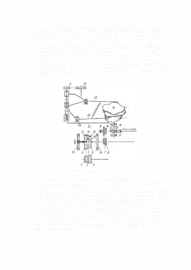
T h e m ac hine is e quipped with t w o elect ri c motors . O n e m otor (Figure
22 )
d rives the cam shaft and is m o unted inside the b e d . The s econd motor
d rives the cutt e r s pindl e and is m o unted in the b ody of the head on a speci al
b ra c k e t . P u l l e y
( 1 , 2, 3 )
on the f i r s t m o to r d rives t h e reduction - gear pul
ley
(4, 5 , 6 )
through a round b e l t .
A
planetary trans m is s io n , consis ting of
the four gears
( 1 3 , 1 4 , 1 5 , 1 6 ),
with a trans mission ratio
1 : 3 . 8 7 ,
is m ount
ed inside pulley
(4, 5, 6 ).
Two brake pull eys
( 1 9, 2 0 )
are m ounted on the
reductio n - gea r s hafts .
21
22
23
0
Reduction-gear shaft
0
FIGURE
22 .
K i nematic diagram of the
S - 5 0
machine
The planetary gea r , intended to reduce the s p e e d of r otation of the r e
duction - gear s haft, consists of t h e two s u n gea r s ,
( 1 3 )
with
3 1
te eth and
( 1 6 )
with
36
teeth, a pinion and two b rake p ull eys .
The s un gear
( 1 3 )
and the b rake pull ey
( 1 9 )
are rigidly connected to each
o th e r , but revolve fre ely on the reduc tion-gea r s h af t .
A
two - s tep sp rocket
wheel
( 7 -
8 )
is rigidly c onnected with the s un gear
( 1 6 )
and the b rake
( 2 0 ) .
The th r e e - s tep pulley
( 4 , 5 , 6 )
i s the planet-pinion c a r d e r . T h e pinion
i n turn c ons ists of two ge a rs ,
( 1 4 )
with
36
t e eth and
( 1 5 )
with
3 1
teeth.
The reduc tio n - gear s haft drives the worm s h aft through the sp rocket
wheels
( 7 ), ( 8 ), ( 9 ), (1 0 )
and a rol l e r chain .
The worm s haft d ri ves the
c a m s haft through the worm
( 1 7 )
(1
tooth ) a nd wheel
( 1 8 ) (45
teeth ) . Six dif
ferent c am s haft s p e e ds can b e achieved using the thre e - s tep pulley
(4 , 5, 6 )
a n d the two - s tep s p ro c ke t
( 7 -
8 )
.
Three cams a r e fitted on the ve rtic al
2 2 !1