Technology of watch production - part 64
 

  Index      Books     Technology of watch production (Tarasov) 1964 year


Search            


Content   ..  62  63  64  65   ..


Technology of watch production - part 64


bushing ( 9 )  som etimes  protrudes  from  the  die  by a  height  equal  to  the  depth 

of the  recess  in  the part  in  order to prevent the  buckling of  thin parts  (Fig­
ure  5 3 ).  Dies  having  recesses  instead of bushings  are  us ed  when the hole 
to be  s haved has  a  deep  countersink at the  exit.  The pres ence  of chips  in 

the  recess  is  evidence  of the correct 

functioning of the punch.  The chips  are 

removed from the reces ses  by a  jet of 

compressed  air .   The  hol e  entrance 

mus t  not hav e  a  counters ink if  it is  to 
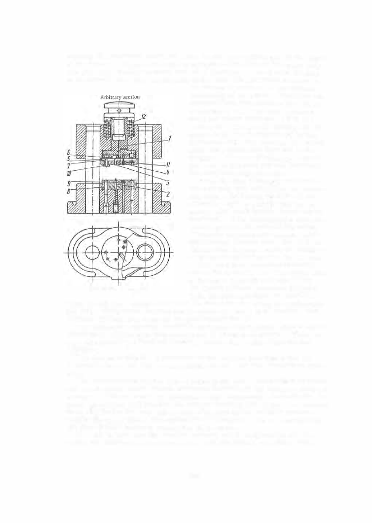
be  s haved.  The  ram  ( 1 )  (Figure  52 )  is 

guided  in the  fixed  stripper  ( 5 )  by the 
guidepos ts  ( 7 ).  The bushings  ( l l ) which 

guide the punches  are fastened in the 

s tripper .  The  use  of bushings  reduces 

the  wear on the  s tripper and inc reases 

the manufacturing accuracy. 

When  the  hole  diameters  are  small, 

the accuracy with which they can be  ma­

chined in a  jig-boring machine  at con­

siderable  depth  is poorer than the ac ­

curacy  with  which bushing holes  can be 
machined .  If the  bushings  are  accurate 

with respect to  run- out and diameter, 

it is  m ore  convenient  to  replace  worn­

out bushings  (by new  ones ]  than  it is  to 

replace  the  s tripper,  s ince  the  s tripper 

is  the m os t  c ritical part  in the die set. 

The part to be  shaved is  manually 

put on the  guide  pin  (2 ).  The  upper  shoe 

is  forced to  descend  with  ram  ( 1 )  by 

F I G URE 

52 . 

Shaving d ie 

the  spring  ( 1 2 )  and  transfers  the  part 

from  the guide pin  (2 )  to  the pins  (3 )

When  the  stripper engages  the  work  the  ram  advances  along the guide bus h ­

ing  ( 1  0 ) .   The  punches  em erge  and  penetrate  the holes  t o  be  shaved.  The 

s tripper  ( 5 )  continues  to press  the  p art  agains t  the  die. 

The design of a  shaving die with forced punch lubrication,  which  reduces 

punch  wear  and prevents  chip adherence,  is  s hown in  Figure  54.  This  de­

sign also p rovides  a  fixed  relationship  between the locating and s having 
elements . 

The  design  of  this  die  is  somewhat  more  complex  than  that of the  die 

desc ribed  above,  but this  is  compensated for by a  greater s tability in  oper­

ation. 

The requirem ents  for the  shaved holes in the plates  and bridges  of pocket­

and wristwatches  are  0. 007 mm  maximum  deviation  of the  dis tances between 

centers ,  0 . 005 mm m aximum  deviation of hole  diameters .  Accordingly,  the 

punch  must be  so  well fitted  in  the  stripper bushing that  oil  can  flow between 

them  only under the  very high pressure' created by the  s tripper upon  im -

pact of  the  upper sho e .   The  spring-loaded plungers  in  the  oil  pas s ages  in 

the  die-set posts  serve  to  control  the  oil pressure. 

In order to inc reas e  the shaving accuracy and to lengthen the die life, 

plates  and  cocks  are  now shaved twice,  and s om etimes  even  three times . 

2 5 3  

The  allowance for the  last  operation  is  0 . 0 1 - 0 . 0 1 5 mm  on  the  diameter. 

The  service life of such a  die (between  regrindings )  can  be as  much  as 

80, 000  strokes .  The punches and dies of shaving- die  s ets  are sharp ened 

directly in the  shoes ,  without  dis mantling  them . 

Stripper 

Workpiece 

Die 

FIGURE 53 .  Shaving-die guide bushing 

FIGURE 54.  Shaving die with forced punch lubrication : 

1 -die ;  2-punch;  3-punch holder;  4-srripper;  5-ring. 

Shaving  dies  are  expensive  tools ,  and  the  following  operational  rules 

have  accordingly been  established: 

1 .   Parts  to  be shaved must be inspected before  shaving in  order  to  as ­

certain  the  existence  of  all  the  holes  which  are to  be  shaved.  The  holes 

are inspected by  a  gage  cons isting  of a  plate and pins  on which the part  is 

freely fitted .   If any  o f  the  holes  is  missing,  the part will  obviously not fit 

on the  pins .  The  inspection can  als o  be  conducted using a p rojection device .  

2 .   The parts  are positioned according to  base  hol es  or along the  con­

tour,  but in s uch a  way as  to ensure positive location . 

3 .   The part  must b e  carefully  cleaned  and  washed t o  remove  chips  and 

dirt,  and  mus t fit tightly in the  die  or stripper. 

4 .   It is not recommended  that holes  whos e  depth is larger than  three 

diam eters  be shave d .   A  higher ratio might lead to  deflection of the punch . 

Measurement  of Hole  Center Coordinates 

The pos ition  of the hole  c enters  in plates and cocks  is  given in  Cartesian 

coordinates  which  are also used to  define  the  centers  of the  reces s e s ,   so 
as  to  provide uniform  system  of designations  in the  drawings .  The  values 

of  the  coordinates  and the  radii of  the  reces s es  are  listed in a  table .   The 

centers  of  holes  and  radii  are p rojected on a  horizontal plane  and  are  de­

s ignated by numbe rs  with  s ubscripts . 

2 5 4  

The  coordinates  x 

1 00 mm,  y 

1 00 mm  are  assigned  to  the  center­

wheel  center o r  to the  centers  of the  minute and hour  hands  in watches . 

This  ensures  that  the  coordinates  of  all  points  on  the  part  will  always  be 

positive,  that is ,  the part  will always  be situated in  the  first  quadrant of 

the  coordinate  system . 

Figure  55  shows  the  position of  the  train  bridge  with  the  table  of  coor­

dinates  for the basic points .  The diam eters  of the holes  in cocks  and plates 

FIGURE 55 .  Coordinates of the 

holes  in  the  train  bridge  of 
" Pobeda"  watches 

Point No. 

II 

Ill 
IV 

Point coordinates 

100 

1 00 

96.565 

1 01.394 

93.500 

92.825 

90.640 
90.750 

87.845 

100 

96.804 

1 06.5 

93.400 

101 .500 

are  m easured  us ing plug gages  or toolmakers 

microscopes .  The  coordinates  of  the  hole  cen­

ters  may be measured using the UIM - 1  universal 

m eas uring microscope  (Figure  56 ),  the  Haus er 

(Switzerland )  jig-boring m achine  (models  1  and 

2A ),  and  the  Hauser coordinate -measuring ma­

chine  (model R - 324 ). 

The  unit  of division on the  s cales  of the 

above - listed  machines  is  0 . 0 0 1  mm . 

The  UIM - 1  universal  m easuring micros cope 

is  little  used  for  coordinate  measuring becaus e 
it  has  neither a  circular  rotary table  nor a 

s upe rimposed - image  head . 

The  machine  mostly used for measuring the 

coordinates  of watch parts is the model- 1 Hauser 

coordinate- marking machine  (Figure  5 7 ) .  

The  limit o f  displacement o f  this  m achine is 

1 0 0 mm X 1 00 mm .  

A  1 2 0  mm  diameter three-jaw  chuck i s  mount­

ed at the upper end  of  the  lower  vertical  spindle 

of the machine ,  the lower end  of which spindle 

carries  a  dis k  with angular divisions  and a 

vernier of  0°02 1 accuracy.  Parts  are positioned 

in this  machine  with an accuracy of  0 . 002 m m .  

The  reading accuracy has  been increas ed to 

0°00 1 0511 in  the  latest  models . 

The  R - 3 2 4  coordinate- measuring insturment 

(Figure  5 8 )  uses  a  gear- and-rack mechanism 

for  moving the  slides .  There are no microm etric  s crews .  The  coo rdinates 

are  m easured by two  lateral  microscopes  with  reticules  (Figure  5 9 ) .   The 

central  microscope is  exchangeable  and  the  magnifications  available  are 

3 5 X  and  4 5X. 

The  part is  positioned  either  on a  flat table  with  independent  coordinate 

displacements,  or  on  a  rotary  table  with  scale divisions  of  0°00 1 05" on  the 

vernier  (Figure  6 0 ).  The  linear  positioning accuracy is  0. 002 m m .  

The  point  coordinates  a r e  m easured i n  t h e  No .  1  machines  and  the  R - 3 2 4  

instrument by  positioning the part  o n  the  machine  table ,   aiming at the  center 
of the hole  to be measured,  recording the m easured coordinates  and calcu­

lating the deviations,  if any. 

For measuring,  the part is positioned  on the  table  either by centering and 

then locking,  or  by  s etting according to  two  holes . 

When using the  first  method,  the  cente r  of hole  1  (the  centering hol e )  

(Figure  6 1 )  i s  made to  coincide  with  the  center of the  microscope  reticule 

and  the  part is  then  fastened  to  the  work table .   The  center o f  the  table  mus t 

2 5 5  

coincide  with  the  center microscop e - grid cross hairs and the machine slides 
be  s et  in the  middle position. 

The  center of hole  (2 )  (the locking hol e )  is  made to  coincide with the 

cross  hairs  of the  microscope  reticule by displacing the s lides  according 

to  the  coordinates 

x2y2 

of  the  locking point and  rotating  the  part  table  from 

position  1 '  into position 2 .   The  table is  locked  in this position. 

FIGURE 56 .  Ullv! 

-1 

uni versa! microscope 

FIGURE 57 .  Model-l  Hauser coordinate-marking 

machine 

2 5 6  

I FIGURE 58 .  R-324 Hauser coordinate-measuring 

instrument 


Content   ..  62  63  64  65   ..