Technology of watch production - part 68
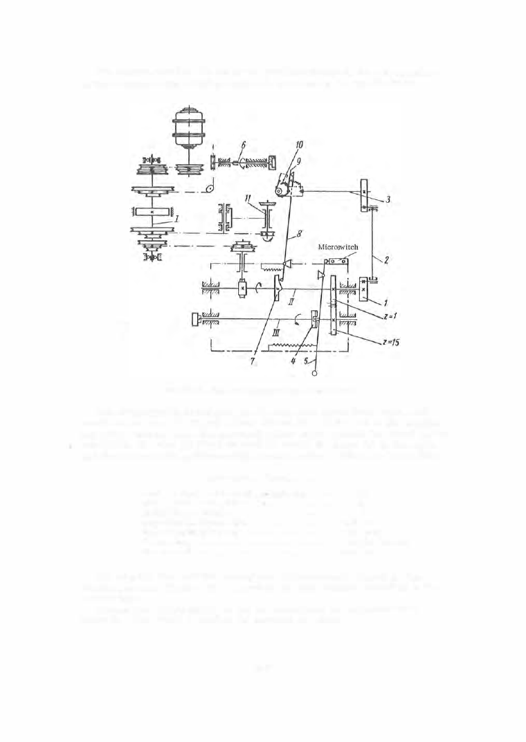
The escape wheel is fed under the grinding wheels on the two spindles
by the rocking of the dividing head ( 1 0 ), mounted on the spindle head .
FIGURE 14. Kinematic diagram of the S-125A machine
The dividing head is indexed one division (one wheel tooth ) upon each
revolution of cam ( 7 ) through levers (8 ) and ( 9 ) . At the end of the machin
ing cycle , that is, when the one - tooth pinion
Zt
has rotated the wheel
z16
one
revolution, the stop (4 ) fitted on shaft III move s the lever ( 5 ) to the right,
and the microswitch switches off the electric moto r . This stops the machine .
Technical data, S-125A machine
Maximum diameter of the wheel machined, mm
.
. . .
1 5
Number o f teeth o n the wheel machined
.
. . . . . . . . .
15
Number of camshaft speeds
. . . . . . . . • .
.
.
•
.
. . . .
6
Range of camshaft speeds, rpm
. . . . . . . . •
. . . . . . .
24.7-32
Range of spindle speeds, rpm
.
• . . . . • • . •
.
. . . . . .
1150-4420
Electric motor .
. • .
.
.
•
.
. . . . . . • • •
.
. . . . . . . .
0.25 kw, 1 500 rpm
Time per cycle, sec
.
. • . . . . . . . . . . . . . . . • . . • .
6 .8-36.4
The impulse face and the locking face are accurately ground on the
S - 1 2 6A machine (Figure 1 5 ). The wheel is again located according to the
central hole.
The-surface finish quality of the two faces must be not poorer than
class 1 2 . One wheel is held on the mandrel at a tim e .
2 6 9