Technology of watch production - part 41
 

  Index      Books     Technology of watch production (Tarasov) 1964 year


Search            


Content   ..  39  40  41  42   ..


Technology of watch production - part 41


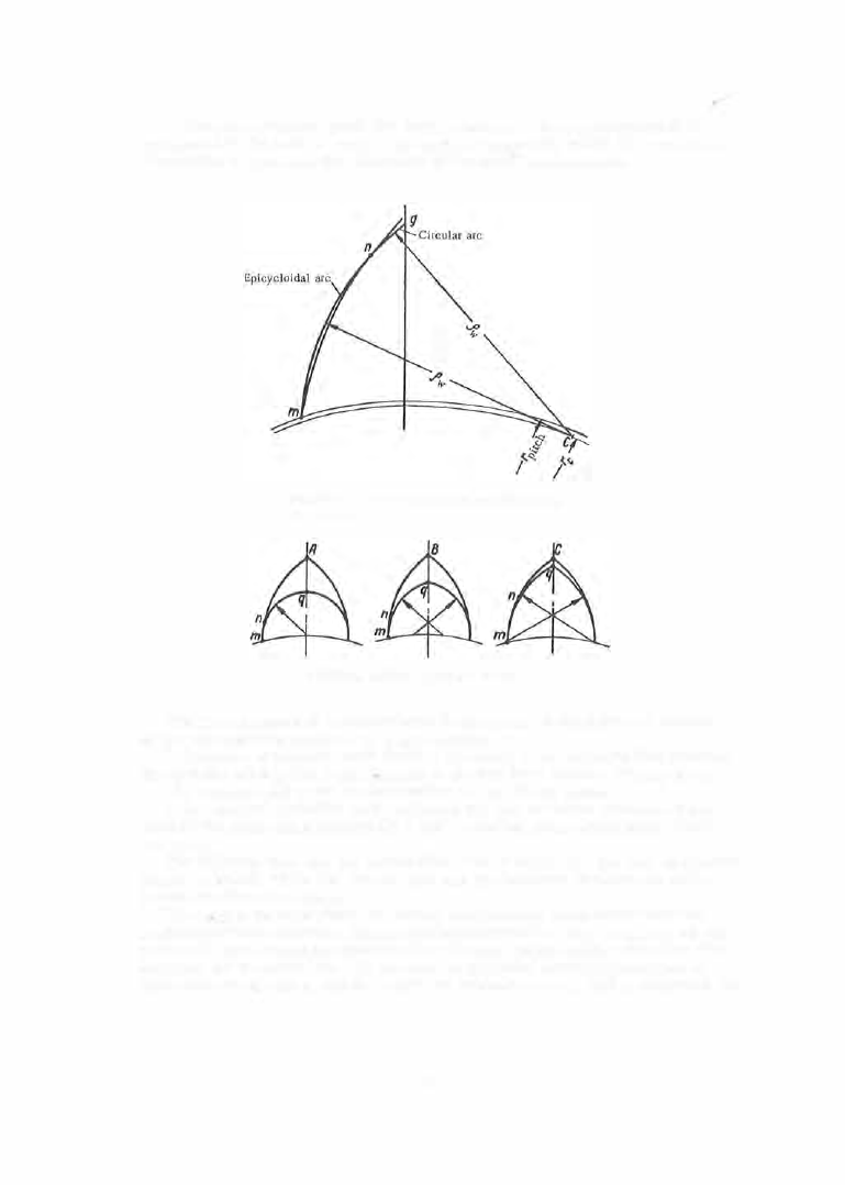
In  the  case of pinion  teeth  the  main  reason for  the  replacem ent  of the 

epicycloid is  the need  to  reduce  the  angle  of approach,  which  in turn  makes 

it possible  to  inc reas e  the  efficiency of  the  gear  transmiss ion. 

FIGURE' 3.  Replacement o f  the epicycloidal arc by  a 
circular arc 

FIGURE 4.  Profiles of pinion teeth tips 

The  line  of  action  of  a  m eshed  pair is  the  locus  of  the  points  of  contact 

of  the  two  mes hing contours  on a  given plane . 

In  the  case  of  involute  teeth  the  line  of  action is  the  straight  line  pass ing 

through  the pitch point 

and tangent to  the two  base  circles  (Figure  5,  a ) .  

The  s egment 

AB 

is  the  active portion  of the  line o f  action . 

In  the  case  of cycloidal  tooth  contours  the  line  of action cons ists  of two 

arcs  of the  generating circles 

A P  

PB 

,  meeting  at the  pitch  point 

(Fig­

ure  5,  b ) .  

The  follower face  and the  driver flank a r e  i n  action  till  the  line of centers 

01 02 

is  reached,  while  the  driver  face  and  the  follower  flank are  in action 

beyond the line  of centers . 

The  augles  through  which  the  driver  and  follower teeth  move  from the 

beginning of their contact to the line of centers are called t h e   a n g l e s   o f   a p ­

p r o  a c h ,  while the angles f rom the line of centers to the end of contact are  t h e 

a n g l e s   o f   r e c e s s i o n.  In  the  case  of  cycloidal  gearing  the  angles  of 

approach are 

cx1 

and 

ctz 

and  the  angles  of  recession are 

�1 

and 

�z 

(Figure 5 ,  b ) .  

1 6 1  

The  sum  of the  angles  of approach  and  recession for each wheel  must be 

equal  to or larger than its angular pitch: 

IX +  p 

where 

is the 

number of teeth  on  the  wheel . 

The  values  of  the  angles  of  approach  and  recession fo r  the  basic  gear 

pairs  of watch mechanis ms  are  given in Table  1 .   If thes e  gear pairs  had 
teeth with involute  contours,  the  angles  of approach would have been be­

tween  2 0  to 2 5 ° .   The  advantage  of the watch  gearing over involute  tooth 
form  gearing is  clear  considering the  fact  that  the  friction losses  decrease 

with decreas ed angle  of approach. 

FIGURE  5. 

Line of action : 

a-involute profiles;  b-cycloidal profiles. 

TABLE 

Angles  of approach  and recession in watch gearing (shortened) 

Number ofteeth : 

Angular pitch 

Angle  of 

Angle  of 

Pinion tooth form 

lvheel -

zw: 

of pinion 

approach 

recession 

(ace. to Fig.4) 

pinion- zp 

Zw = 60 

Zp  = 6  

60° 

17°44'13" 

42" 1 5'47" 

Zw = 70 

5 1  °25'43" 

1 1°30'28" 

39°55' 1 5" 

Zp  = 7  

Zw = 60 

Zp  = 8 

45° 

7°23'40" 

37°36'20" 

Z w= 

64 

45° 

7°17'30" 

37°42'30" 

Zp  = 8  

Zw = 80 

45° 

6°59'5" 

38°0'55" 

Zp  = 8  

Zw= 75 

360 

1 °20'7" 

340S9'53" 

Z p  =  1 0  

Zw= 80 

36° 

1°14' 1 2" 

34°45°48" 

Z p  = 10 

1 6 2  

In  watch  gearing  the  line  of  action  will  deviate  from  the  theoretical 

curve 

AB 

( Figure  5, b )  at  those  s ections  where  the  circular  arcs  do  not 

coincide  with  the  epicycloids .  This  deviation  disturbs  the  trans mission 

ratio of the meshing pairs (within the limits  of one pitch ),  and  in  consequence 

the  moment transmitted is  altered and the  accuracy is  disturbed.  This  is 
the main s hortcoming of watch gearing. 

In  order to  reduce this  deviation to  a  minimum ,  the active portion  of the 

wheel tooth p rofile 

-

(see Figure  3)  and of the pinion tooth p rofile  (Fig­

ure 4 ,   shape 

C), 

are made  to  approximate  the  epicycloid  as  clos ely  as  pos­

sibl e .  

The basic paramete rs  of watch  gearing a r e  given i n  A ppendix 2  (Standards 

of the  Glavchasprom  (Watch Industry C ente r ) ) .  

The  tolerance o n  the  center distance  must b e  narrower f o r  cycloidal  and 

watch  gears  than for  involute  gears . 

Deviations  in  the  c enter  dis tance  will  produce ,  in the  case  of  cycloidal  or 

watch gearing,  a  contact either between two hypocycloids  or two  epicycloids 

and this  obviously will  disturb  the  trans mis sion  ratio .  In involute  gears 

the  transmission  ratio  is not affected by s uch  deviations . 

The  influence  of  radial  wheel  run- out  o r  an  increas e  or  decreas e  in its 

diameter is  s imilar to that of a  deviation in the  center  distance .   A ccordingly, 

narrow  tole rances  are fixed  for  thes e  param eters . 

Jewel bearings  are used in watches  in order to  reduce  the  friction los ses 

in  the  b earings  and  to  increas e  the  efficiency  of  the  gear transmis s ion. 

Photographs  of a  wheel,  pinions ,  and a  claw clutch are given in Figure  6 .  

FIGURE  6.  Toothed  watch parts 

a-chronograph wheel;  b-third-wheel pinion;  c-cannon pinion;  d-claw clutch. 

Wheels  and pinions  have  spur teeth.  The  claw  clutch and  the  winding 

pinion have  face  teeth  - formed and angular .  

I n  order t o  obtain high performance from  the  gear transmission i t  is 

neces sary that the wheels  and pinions  have accurate  dimensions  and that 
the wheels  have  a  class  8  or 

s urface-finish quality,  and  the  pinions  a 

1 6 3  

class  1 1  to  1 3  finish.  In  order to  ensure  accurate  center  distances  in 

plates  and  bridges ,  the  holes  are sized  (see Chapter VI ). 

TOLERANCES  ON GEARING  ELEMENTS 

Accuracy  classes and  tolerances  for  2 0°  pressure  angle  involute  gearing 

elem ents  of module  1 mm and above  have been  established by GOST  1 6 4 3 - 4 6 .  

Only  departm ental  standards  exist for involute  gearing of  module  0 . 1 5 - 1 m m .  

Tolerances  us ed i n  watch  industry  for  watch  gearing  correspond to  the 

departmental  specifications  NPM5 - 24 6 - 5 3  (see Table  2 ). 

The  departmental  specifications  establish  tolerances  for  six  gearing 

elements .  The  table  has  been prepared  so  that  the  numerical  values  of  the 

tolerances  for 

/lD 

!lA 

and 

8f 

are  taken with  a  geometrical -progression 

factor of  1 .4 1 ,   and for 

!ld ,  /ls 

and 

8t 

with a  factor of  1 . 2 6 .  

Drawing 

TABLE  2 

Tolerances for  basic watch-gearing elements,  in microns 

Tolerances 

Maximum run-out, 

outside diameter 

Tolerance, external 

diameter 

1 6 4  

Symbol  Accuracy 

class 

lld 

llD 

Module, mm 

"" 

o

a ;;!  

.....  � 

..-< 

0 �  

E o  

.....  � 

12 

12 

15 

1 5  

19 

12 

14 

17 

20 

24 


C'> 

' o  

o ., 

E o  

� 8  

15 

1 9  

19 

24 

24 

30 

15 

1 9  

2 1  

26 

28 

35 


Content   ..  39  40  41  42   ..