Technology of watch production - part 42
 

  Index      Books     Technology of watch production (Tarasov) 1964 year


Search            


Content   ..  40  41  42  43   ..


Technology of watch production - part 42


Drawing 

TABLE 2 (cant' d) 

Tolerances 

Tooth-thickness 

tolerance 

Profile tolerance 

M aximum difference 

betlveen adjacent 

circular pitches 

Center distance 

tolerance for 

a gear pair 

1 6 5 

Module,  mm 

Symbol 

� 

class 

� 

ci 

'"""! 

0 "' 

'"""! 

"' 

'"""! 

0  0 

� 

J: 

"" 

E  :;; 

� 

t.A 

� 

� 

12 

15 

12 

15 

1 9  

15 

19 

24 

1 0  

1 0  

12 

14 

12 

± 7  

12 

12 

15 

15 

19 

± 9   H2 

1 9  

24 

30 

12 

16 

15 

19 

24 

± 1 6  

±10  ±13  ± 17 

± 22 

t 14 

! 18 

± 23 

i30 

1-' 

Gl 

Gl 

FIGURE  7.  Methods  of holding and positioning blanks  in machines : 

a-pinion blank  between  female centets;  b-cannon-pinion blank 
between male centers;  c-mounting and holding winding wheel 
blanks;  d- mounting wheel blanks  by sector windows;  e-moum­
ing and holding barrel-wheel blanks;  f-mounting and holding 

wheel stacks. 

Section A -A 

-

.. , 

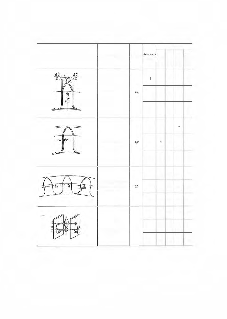
Table  2  does  not  include  tolerances  for  the  bas e  pitch 

A.t 

o r  for the  dis ­

placement 

lih 

of  the  basic  rack as  do  the  involute  gear tolerances ,  since  the 

pitch  circle  and  the  bas e  circle  coincide in cycloidal and in watch  gearing, 

and  the  param eter 

8h 

is  r eplaced  by the parameter 

AD 

in s harp-tipped  teeth . 

Mounting Gear Blanks  in Machines 

The blanks  are  fas tened in  the  heads tock of the  machine  dividing-head  and 

the  tailstock serves as  a  s upport  only.  The  methods  of  holding  and  position­

ing vary,  depending upon the  design  of  the blanks . 

The  mounting of a  pinion blank between  female  centers  is  shown  in  Fig­

ure  7,  a.  The centers have clearance  holes  for the journals .  The blank is 
located  on  chamfers  and the  conical notches in the  driving center  grip  the 
chamfer s o  that the  blank  rotates  with  the  center .   The  tailstock  cente r 

s erves  as  a  s upport. 

The cannon-pinion blank is  mounted between male centers  (Figure  7, b ) .  

The  driving center grips  the  hole  chamfer,  with  its  s harp  edges  forcing the 

blank to  turn with  the  center.  The  tailstock center s erves  as  a  support. 

Barrel-wheel blanks  having a  small-diameter  central  hole  are  s et  on 

the mandrel  ( 1 )  in a  s tack  (Figure  7, c) and are mounted between  centers . 

Here both centers  are knurled  on  their  faces  and  drive  the  work .  The  tail­

stock center  rotates  with the  mandrel,  the  ball  (2 )  s erving as  a  thrust bear­
ing.  The tailstock spindle retracts together with the center,  being connec ted 

to  it by  the  s et  s c rew  ( 3 )  which  fits  into  an annular  groove  on  the  cente r .  

Wheels  having sector  windows  i n  addition t o  the  central  hole  are  mounted 

on  s ector  tongues  on  the  mandrel  (Figure  7, d ) .   The  mandrel  {2 ) i s  center­

ed by  a  recess  on the s houlder of the headstock spindle nos e .   The  nut  ( 3 )  

serves  for p ressing the  blanks  against the  mandrel  s houlder .  The  center (4 ) 
fits  the  mandrel  hole,  its female cone accommodating the tailstock center ( 5 )  

The pin  ( 1 )  serves  as  a  driver  for  rotating the  mandrel . 

The  mainspring  barrel  with  a  3 . 2  mm  diam eter hole  (Figure  7 ,  e )  is 

mounted  and  held on  the  mandrel  ( 1 )  which  has  a  s hank fitting  the  dividing­

head spindle  bore  and  replacing the  driving center .   The chuck (2 ) is mounted 

in the  tailstock c enter and the pin  { 3 )  centers  the blank in the  mandrel . 

The  mounting  and  positioning  of wheel blanks  for  stack milling is  s hown 

in Figure  7 ,  f .   The  method  of milling in stacks  is  used  for  wheels  whose 

run  out in the s tack mus t not exceed 0 . 0 1  mm. 

MILLING  TEETH  USING  FORMED  CUTTERS 

The  methods  used for milling the  teeth of wheels  and pinions  in watch 

p roduction are  the  form-milling method  (division),  us ing a  profiled disk 

cutter,  and  the  generation method using a  hob . 

The  form - milling method  is  used for milling  the  teeth  of  ratchet wheels , 

segments  and  pinions  with  fewer  than  1 2  teeth  (z < 

1 2 ) . 

If  hobbing machines 

are not available ,   wheels  and pinions  with more  than  12  teeth  can  also  be 
form - milled. 

1 6 7  

The  p rofile  of  the  milling cutter (Figure  8 )  corresponds  to  the  p rofile 

of  the  tooth  spaces  of  the  wheel  or  pinion  to  be  milled. 

When one cut  has  been completed  the  blank is automatically indexed  by 

the  angle  3 6 0°/ z  ( z  =  the  number of teeth  on  the  wheel  or  pinion  to  be milled), 
and  another tooth  space is milled. 

Pinions  are milled one at a  tim e  and  thin wheels  are milled in stacks  of 

30  to  50  pieces . 

The  milling is  performed  on  specialized automatic  and  s emiautomatic 

machines  (models  S - 4 0 ,   S - 5 1 ,   S - 5 3 ,   S - 1 8 6 ,   etc . ) .  

The  S - 4 0  automatic  gear-milling  machine 

is  des igned f o r  milling wheels 

and pinions  with a  maximum  module  of  0 . 5 mm  for  brass and  0 . 3 5 mm  for 

FIGURE 8 .   Tooth milling 11ith a formed cutter 

steel,  over a  milling length  of  1 2  mm . 

If  the  blanks  are loaded  manually, 

blanks  up to  20 mm  diameter can  be 

milled .  If  magazine  loading is  us ed, 

the  maximum  diameter is  5 mm.  The 

machine  can  operate  automatically o r  

s emiautomatically. 

Power  is  trans mitted from  the 

electric- motor pulley  ( 1 )  through  a  flat 

belt  to  the  pulley  (2 )  on counters haft I 

(Figure  1 0 ) .   Pulley  (4 )  or  (5) on coun­

tershaft II is  driven by pulley  (2),  and 
pulley  ( 3 )  drives  either pulley  ( 1 4 )  or 

( 1 5 )  on the worm-gear s haft  ( 9 ) .  

Pulleys  (4 )  and  ( 1 4 )  are keyed to 

their s hafts  while  ( 5 )  and  ( 1 5 )  a re  idl e rs .  Shaft II drives  the  worm  ( 1 8 )  

through  the  three-step pulleys  ( 7 )  and  ( 1 3 )  (round  belt) and  the  rotation  is 

transmitted  through  the  worm  gear  ( 1 8 - 1 9 )  to  the  main camshaft .  The 

formed  cutter spindle  is  driven  from  countershaft II by a  round  belt  on 

pulley  ( 1 2 )  and  the  two -step pulley  ( 6 ).  The belt passes over the  guide  idlers 

( 1 0 )  and  ( 1 1 ).  The  auxiliary  camshaft is  powe red f rom the pulley  ( 14 ) through 

the  worm  gear  ( 9 - 1 7  ).  The  coolant- feed gear pump  is  driven  from  counter­

shaft II by pulleys  ( 8 )  and ( 1 6  ). 

Starting and stopping of the shaft II is  automatic .  The automatic  action 

of the  machine is  controlled  by fixed  cams  mounted  on the  main and  auxiliary 

camshafts  ( Table  3 ). 

The  machine  operates  as  follows : 

The  cam  A  advances  the  table  with  the  dividing head from  left to  right  in 

a  uniform  motion.  The  form  cutter  mills  one  tooth  space .   The  cam  B  then 
lifts  the  milling- cutter head  in  order to  enable  the  table  to  return  freely, 

without the cutte r  s c ratching the  blank.  The  drop  in  the  profile  of  cam  A 

allows  the  table  to  be  returned  to  the  left by  a  spring.  Cams  C  and D  then 
go  into  action .  Cam  D  lifts  the  left  end  of the  lockpin l ever  and  pulls  it  out 

of  the  index plate  slot.  Cam  C  next  lifts  the left  end of the push lever,  and 

the pawl  goes  down,  rotating the  ratchet wheel,  and  the  index plate  together 

with  it,  by  one  tooth .  The  ratchet wheel  is  fitted in the  sam e  bushing as  the 
index  plate  and  the  relative pos ition  of the  ratchet-wheel  tooth  and  the  index­

plate slot is  adjusted by means  of  special bolts  during the machine  s etup . 

The  ratchet wheel  and  the  index plate  have  the  same number of  teeth  as 

the  wheel to  be  milled,  or  a  multiple  the reof .   Both disks  are  replaceabl e . 

1 6 8  


Content   ..  40  41  42  43   ..