Technology of watch production - part 39
 

  Index      Books     Technology of watch production (Tarasov) 1964 year


Search            


Content   ..  37  38  39  40   ..


Technology of watch production - part 39


The  diameter of  the  collet hole  is  equal  to  the  nominal  diameter of  the 

bar  with  the  tolerance  of  class  2  accuracy  suitable  for  a  close  running 
fit .  The  use  of  collets  having slightly  different  dimensions  is  not  recom ­

mended  as  an additional  run- out appears  as  a  result of  the  incorrect grip ­
p ing of the bar  stock and  the  collet rapidly loses  its  sp ring p roperties .  The 

collet  has  brazed carbide inserts  which increas e  its  durability 4 - 5  tim es . 

C ollets  with  carbide  inserts  are  slotted by  m eans  of  diamond  cutting disks . 

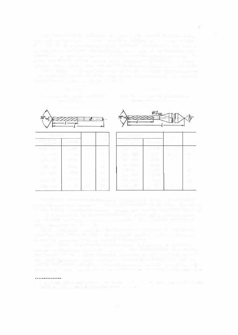
Twist drills .  Left- hand  twist drills  are  used on Swiss -type  automatics .  

The  types  and  dimens ions  of the  twist drills  most frequently use d  i n  watch 

p roduction are  given in Tables  1 9  and  2 0 .  

TABLE  19 

Dimensions of straight-shank twist drills with 

ground flutes, mm 

Drill diameter 

nominal di-

tolerance 

Inension 

0.025-0.30 

-0.008 

1 8  

0.32-0.40 

-0.0 1 0  

20 

0.42-0.50 

-0.010 

22 

0.52-0.60 

-0.01 0 

24 

0.62-0.70 

- 0.01 2 

26 

0.72 - 0.80 

-0.0 1 2  

28 

0.82- 1 .00 

-0.0 1 2  

1 0  

30 

TABLE  20 

Dimensions of twist drills with ground flutes and 

oversize straight shanks, mm 

Drill diameter 

nominal di-

Inension 

tolerance 

0. 1 0-0.20 

- 0.006 

1 .5 - 2.5 

1 5  

0.2 1 -0.30 

-0.008 

2.5-3 

1 5  

0.32-0.40 

- 0.0 1 0  

1 8  

0.42- 0.50 

-0.0 1 0  

20 

0.52-0.60 

- 0.0 1 0  

22 

0.62-0.70 

-0.01 2  

24 

0.72-0.80 

- 0.012 

24 

0.82 - 1 .00 

- 0.012 

10 

28 

Drills  with  o ve rs ized shanks  make it pos s ible  to  reduce  the  number of 

collet dimensions .  Because  of  the  s m all  diameters  of the  drills ,  the  helical 

flutes ,  having  a  particular c ontour,  are  ground from  the  hardened  blank / 1 2 /  

The  tole rance o n  the  working diameter is  according t o  accuracy class 

2 a':'  of GOST  3 04 7 - 54 .   The drills  are  made  of type R 1 8  high-speed  steel 

with a  hardness  Rc=  59  to  6 2 .  

U 1 0A - U 1 2A  steel  i s  not  us ed for d rills  as  the  drills  are  heated by  the 

grinding  wheel  (when the flutes  are  ground),  and this  would  cons iderably 

reduce  the  hardness  of  drills  made of these steels . 

Taps . 

Watch m echanisms  us e  right- hand,  and  sometimes left- hand, 

threads  of  diameters  from  0 . 3  to 2 . 6  mm.  The thread-profile angle  is  50°, 
for  threads  of 0 . 3 - 0 . 9  mm diam eter,  according to  GOST 3 1 96 - 4 6 ,   and 6 0° 

for watch  th,reads  of  larger diameters ,  according to  GOST  7 2 1 7 .   The  50° 

p rofile  has  s e ve ral  advantages  over  the  generally used  6 0°  p rofile for  small 

diameters .  The  s trength  of the thread increases  as  a  result of the  increas e 

•  [A  1st  accuracy  class  fit corresponds to an extra  fine fit,  a 2nd accuracy  class  fit to a fine  fit,  a  3rd  accuracy 

class fit to  a plain fit,  and a 4th accuracy class fit to a rough fit. ] 

1 5 3  

in  its  depth  and  the  thread wear  rate  decreas es  as  a  result of  the  increas e 
in  the  flank  area.  A mong the  sho rtcomings  of 50° threads  is  a  certain 

weakening of the  s crew or  tap  body  as  a  result of the  decreas e  in the  root 
diam ete r. 

The  ove r - all length and the  threading length  of the  taps  used fo r thread­

ing 0 . 3 - 0 . 9  mm  diameter threads  are different from  thos e  generally  ac­

cepted  (see Table  2 1  ).  

TABLE  2 1  

TABLE  22 

Dimensions and shape of triangular taps,  mm 

Dimensions of three-flute taps, 

111111 

I, 

I, 

0.3 

0.075 

1 6.8 

2.6 

0.5 

0.1 

0.35 

0 .075 

1 6.8 

2.6 

0.5 

0 . 1 2  

0.25 

27.7 

1 .5 

0.40 

0 . 1 00 

18.8 

3 5  

0.6 

0. 1 5  

1 .2 

0.25 

27.7 

1

.

0.45 

0. 1 00  

18.8 

3.5 

0.6 

0 . 1 7  

1 .4 

0.30 

30 

1 0  

1 .75 

0.50 

0 . 1 25 

20.9 

0.75 

0.2 

0.55 

G . l 25 

20.9 

0.75 

0.22 

1 .7 

0.35 

32 

1 2  

0.60 

0. 1 50 

20.9 

0.85 

0.25 

2.0 

0.40 

35 

1 4  

2.3 

0.70 

0. 1 75 

20.9 

0.25 

2.3 

0.40 

35 

1 4  

2.3 

0.80 

0.200 

23.0 

1

.

0.30 

2.6 

0.45 

38 

1 6  

2.

0.90 

0.225 

23.0 

1 .3 

0.30 

Triangular  taps  track reliably into  the  hole,  have a  s mall  cutting-lip 

width, and  are  stronge r  than taps  of the  usual  s hap e .   Their s hortcoming 
lies  in their large  negative  rake angles ,  as  much  as  4 0°  at the m ajor dia­

meter,  and  7 0°  at the  minor  diameter.  Cutting is  replaced to  a  consider­

able extent by  s craping when these taps  are used,  and this  requires  an ad­

ditional  effort. 

Triangular taps  have insufficient  clearances  for chip  removal  and s uch 

taps  are  therefore  not used  for threading holes  of a  diam eter larger than 

1 mm  in brass  and  steel ,  nor  holes with a  depth  greater  than  1 . 5d. 

Three - flute  taps  are  us ed for threads  of diameter larger than  1 . 0  mm  and 

depth m o re  than  1 . 5d .   The  dimensions  of thes e  taps  are  given in Table  2 2 .  

The  three - flute  taps  have  zero  rake  angles  and  this  gives  considerably 

improved cutting conditions  as  compared with  the  triangular tap s .  

The  flutes  als o  provide  s ufficient chip  space . 

1174 

1 54 

The  b ody s ection  of  three -flute  taps  is  somewhat weakened  and  it  is  more 

difficult to mill the flutes  in these taps  than in the triangular taps .  Three­
flute  taps  are made from  U 1 OA - Ul2A  s teel .  

Chaser dies . 

Three  standard  types  o f  chaser dies  are us ed i n  watch 

production:  round ,  nonadjustable ,   thread-forming tools without chip  spaces 
for cutting  threads  of  0 . 3 - 1 .2 mm  diameter;  tubular adjustable  chasing dies 

with chip spaces  for cutting threads  of  0 . 3 - 1 .  7 mm  diameter;  and round, 

nonadjustable  dies  with  chip  spaces  for  cutting threads  of  1 . 0  to  2 . 6  mm dia­
meter. 

The round,nonadjustable  dies without chip  spaces  are flat disks  with 

tapped  holes  (see Table  2 3 ). 

TABLE  23 

TABLE  24 

Dimensions of round dies without chip spaces, mm 

Dimensions of tubular dies, 

m m  

11 

/1 

/1 

0.3 

O.D75 

0.35 

0.60 

0. 150 

0.60 

0.35 

O.D75 

0.35 

0.70 

0.175 

0.60 

0.40 

0.1 00 

0.35 

0.8 

0.200 

0.60 

0.45 

0.100 

0.35 

0.9 

0.225 

0.70 

0.50 

0.1 25 

0.40 

1 .0 

0.250 

0.90 

0.55 

0. 1 25 

0.40 

1 .2 

0.250 

0.90 

0,30 

0,075 

0.5 

0.70 

0.175 

0.35 

0,075 

0.5 

0.80 

0,200 

0.40 

0.100 

0.5  0.90 

0.225 

0,45 

0.100 

0.5 

1 .00 

0.250 

0.50 

0. 1 25 

0.5 

1 .2 

0.250 

6.5 

0.55 

0, 125 

1 .4 

0,300 

0.60 

0,150 

1 .7 

0,350 

1.4 

1.4 

1.4 

1.6 

1 .6 

The  die  hole  is  chamfered at both ends  and  its  thickness  must  not exceed 

three thread pitches .  The  depth of the  chamfer is  0 . 7 5 s  and  the  cutting and 

calibrating portions  of the  die  are  equal  in length. 

An increase  in the  thickness  of the  die leads  to  the  s wift wors ening  of the 

threading conditions,  to j amming of the  part  in the  die  and  to  breaking off 

of the  part. 

A  notch is  cut on the  end plane of the  die to ameliorate  the conditions of 

thread formation.  The  s ervice life  of thes e  dies  is  not long (400 to  6 0 0  

threads ),  but their manufacture is  simple .  The blanks  for them  are  stamped 
from  a  s trip . 

The  tubular,  adjustable dies are  mainly used for threading in specialized 

automatic  machines .  Their dimensions  are  given in  Table  2 4 .  

Tubular dies  have  three cutting lips  with positive  rake  angles .  The 

threads  are  cut,  and  not formed as  by the  first type  of  die .  The  dies  are 
adjustable ,   which is  particularly important when the  mechanical  properties 

1 5 5 

o f  the bar  stock are  not  uniform .  When  the  lips  dull  they  can  be  res harpened 
by  grinding the  faces,  and  if  the  part  being  threaded  breaks  it  can be  re­

moved from  the  die by removing the adjusting  ring  and forcing the lips apart. 

A  die  without  chip  spaces  must be  dis carded in  s uch  a  cas e .   The  s ervice 

life of tubular chasing dies  is  5 - 6  times  longer than  that  of the forming dies , 

but  their production  requires  s everal  tim es  more labor and  mate rials .  The 

adjustable  chasing dies  are  better  than the  forming dies  for  use  in  mass 

p ro duction . 

Round  die s ,   nonadjustable  but  with  chip  spaces ,   are  us ed  for cutting 

threads  of  1 mm  diameter and larger.  Their advantage  relative  to  the  dies 
without  chip  spaces  lies  in  the pres ence  of three  cutting faces  with positive 

rake  angles  and with windows  for  chip  removal  (see Table  2 5 ). 

TABLE  25 

Dimensions of round dies,  mm 

0.25 

2.0 

1 .2 

0,25 

2.0 

1 .4 

0.30 

2.5 

1 .7 

0.35 

2.5 

2.0 

0.40 

3.0 

2.3 

0.40 

3.0 

2.6 

0.45 

3.0 

Round  dies  with  chip  spaces  are  more  expensive  to p roduce than  are 

those  without chip  spaces;  however,  they  can  be  resharpened by  grinding 

the  cutting faces .  The  dies  are  manufactured from  U 1 2A  and  9KhS,  steels . 

Slotting  cutters . 

Table  2 6  gives  the  dimensions  of  the  slotting cutters , 

m ade  of  U 1 0A ,   U 1 2A ,   9KhS  steel s ,   used for slotting s crew heads  and  cutting 

s m all slots  in bushings  and  other parts . 

Measuring  instruments . 

The  outer diameters  and  l engths  of  the  m achined 

parts  are  m easured by micrometers  of  special  design .   Dim ensions  with 

tolerances  of  0 . 02 mm  and larger are  meas ured by  the  horizontal  L- 2 3  mi­

crometer with  divisions  of  0 . 0 1  mm  on the  barrel  and  range  from  0  to  15 mm 

(Figure  34 ). 

Dimensions  with  tolerances between 0. 003 and  0 . 03 mm are  measured by 

me ans  of the  c ombined instrum er.t  K - 6 ,   consisting of  an  indicator with s cale 

divisions  of  0 . 0 0 1  mm and  range ± 0 . 0 3  m m ,   and  a  micrometer head with 

scale  divisions  of  0 . 0 1  m m ,   and  range  0  to  1 0 mm  (Figure  3 5 ). 

1 5 6  


Content   ..  37  38  39  40   ..