Technology of watch production - part 38
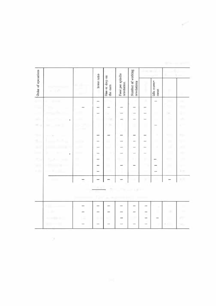
Cam rotation,
degrees, for
Designation of
operations
26th
Plunge No. 5
• • •
27th
Dwell
. • • . • . •
28th Retract No. 5
• • •
2 9th Approach No. 4
Headstock
and tool
travel
0,230
1 ,175
0,945
30th
Plunge No, 4
•
• •
0.1
+
0.025
=
=
0.125
31st
Dwell
• • • . • • •
-
32nd Retract No . 4
,
• •
1 .070
33rd Advance headstock 1 .27
34th
Approach No. 2
0.50
35th
Advance headstock 0.1
l
36th
Advance No, 2
• •
0,1
f
37th Advance No, 2
• •
1.45
T o t a l . . . . .
6
"'
u
0.46
2.35
2: 1 1.890
2
0,35
2,14
2,54
1 .50
0,2
0.3
4.35
0,005
43
0.008
15
0.005
20
0.008
180
540
bO
.s
"
:E
tJ
"'
6
18
10
10
(10)
87
247"
540
X
360
n
=
247
=
790 revolutions per piece
Production rate
A =
5000: 790= 6 .4 pieces per minute
Approach drill . . .
Dwell . . . . . . . .
Advance drill .
, ,
0.85
1:
1
0.85
112
Retract drill . . . .
1 4 9
2
3
3
2
2
4
3
113°
10
10
12
Sheet A-3 (cont'd)
Camshaft posi
tion, degrees
6
�
8
216
234
236
239
242
252
254
256
260
263
263
273
86
96
106
218
234
236
239
242
252
254
256
260
263
273
273
360
360"
96
106
218
230