Technology of watch production - part 17
 

  Index      Books     Technology of watch production (Tarasov) 1964 year


Search            


Content   ..  15  16  17  18   ..


Technology of watch production - part 17


When m ounted  on  a p ress ,   the  die s et  is  fastened  to  the  bolster plate of 

the p ress by m eans  of straps  and bolts . 

The  upp e r  shoe is  fastened to  the  press  ram  by  its  shank,  whos e  head 

fits  into  the  T-shaped slot of the transition shank  fastened  to  the  ram  by 

bolts . 

The  s hank head is  made  spherical  in order to  avoid the  transmiss ion  of 

nonaxial  forces  from  the  press  ram  to  the  upper shoe of the  die  set.  Such 

nonaxial  forces  could  result from  clearances  and  disto rtions  in the  moving 

parts . 

A s  comparatively large  clearances  exis t  between  the  moving  ram  and  its 

guide,  guidepins  are included in  the  die  s et  to  ensure  maintenance  of  the 

proper relationship  between the  uppe r  and  lower  die  elements . 

I! 

lJl 

Smm 

l5 

� 

"' 

4-o 

� 

1.5 

--" 

Bridge 

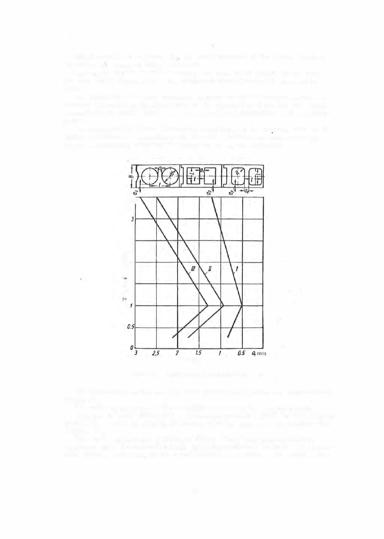
FIGURE 1 1 .   Determination of the width of bridges 

a1 

The  dimensions  of  the  die  s ets  used in  watch production are standardized 

(Table  2 ). 

The  m ain  working pa rts  of  a  blanking  die  are  the  die  and  the  punch. 

Dies  can be made  either with a  cylindrical  portion beyond the cutting edge 

of the  die,  or with an angular clearance  s tarting right from  the  cutting edge 

(Figure  1 2  ) .  

Dies  with  a  cylindrical portion a s  distinct f rom  dies  with a n  angular 

clearance only,  preserve  their s ize  after regrinding of the  fac e .   The  clear­

ance between punch and die  does  not change  in s uch dies .  The cutting  edge 

6 5  

of  dies  with  a  cylindrical  po rtion is  stronger than  that  of  the  other  type ,  

but  a  larger  force i s   required f o r  the  ejection of blanks .  The  relieved 

s ection below the  cylindrical p o rtion of  thes e  dies  may take many forms 

and  has  p ractically no influence on the  blanking p roces s .  

FIGURE 12.  Blanking dies : 

a and b-dies '"ith  a cylindrical portion;  c and d-dies with  an 
angular clearance only,  starting at the cutting edge. 

TABLE  2 

Dimensions of model Sh-01  die sets used in watch  production,  mm 

Die-set dimensions 

No.  of 

die  set 

110 

55 

55 

1 35 

7 0  

7 0  

160 

85 

90 

190 

95 

110 

235 

130 

140 

280 

160 

170 

330 

180 

200 

Limiting-

blank dia-

Hmln 

meter 

1 05 

1 0  

1 3 0  

15 

150 

25 

175 

35 

190 

50 

205 

65 

220 

85 

Dies  of  the  above  type  are us ed for blanking precision parts  and  when the 

blanked parts  have  to be p ress ed back into  the  s trip .  The  width  of the  cy­

lindrical portion is  usually made equal  to  the  thicknes s  of 2  to  5  parts . 

The  wider the  cylindrical  part  (within  certain limits ),  the  m o re  regrind­

ings  the die  can bear,  and the higher its  rigidity. 

Dies  with  angular  clearanc e  up  to  their cutting  edge  do  not retain the 

blanked parts  and therefore no  additional  force is  required for their ejection. 

6 6  

However,  because  regrinding changes  their  dimensions ,  they  are not 

s uitable  for blanking  accurate parts .  The  rigidity  of  such  dies  is  less  than 

that  of  dies  with  a  cylindrical portion  and  they  require  more  frequent  re ­
grindings .  Dies  with  a  full  angular clearance  are also  more difficult  to 

manufacture.  In  order to  overcome s ome  of  the  above  d rawbacks ,  die 

openings  are sometimes provided with a  double angular clearance  (see 
Figure  12,  d ) .   The  clearance in the  working part of the  opening has  a  slope 

Of  0° 1 5  

tO  0°30 

I ,  

While  in  the  nonworking part  the  SlOpe  iS  2° tO  5°. 

The  die blocks  have  holes fo r  fastening to the die s hoes ,  and for the 

m ounting of s tops ,  strippers ,  guides ,  and  other  die  components  (Figure 1 3 ) . 

Punches  are  s ubject to  high  crus hing,  bending and  also  tensile  stres s es . 

In order that  the  punch be  stable  in operation,  it  should  be  as  short  as  pos ­

s ible,  or  be  mounted in a  guide.  If the punch  is  not guided,  holes  to be 

FIGURE 13. 

Punch and die of 

a compound blanking die 

punched s hould not have  a  diam eter smaller  than 

the  stock thicknes s .   Guided  punches  can m ake  holes 

of diameters  down to  0 . 5 - 0 . 7 5  of the  stock thickne s s .  

Examples  of punch mountings  a r e  s hown  in  Fig­

ure  1 4 .  

Dies  and punches  are generally m ade from  high­

carbon  or chromium  tool  steels .  However,  dies 

and punches  used in the p roduction of watch compo­

nents  are frequently made of BK6 ,  BK8,  and other 

hard-alloy grades  (Figure  1 5 ). 

The  durability  of  dies  having cutting parts  made 

from hard alloys  is  1 0 - 1 5  tim es  as  high as  that of 

dies and punches  made of tool steel. 

A  blanking die for an irregularly shaped part  is 

shown in Figure  1 6 .  

To  facilitate  the  manufacture  of these dies ,  they 

are built-up  from  s ections ,  wi'th the  joints  chosen 

in s uch a  way  that  all parts  of  the  contour can be 

machined ,   Sectional  dies are  held  to gether by rings . 

The  rigidity  of  s ectional  dies  is  somewhat lower 

than that  of s olid dies and the considerable  stresses 

sometimes p roduce  dents  at the  joints . 

In  order to increas e  the  durability  of  the  die  s et  it  is  s o  adjus ted  that  the 

punch penetrates  into  the  die to  a  depth not exceeding the  thickness  of  the 

part. 

Strippers. 

When parts  are blanked  or holes pierced,  the punch penetrates 

the  entire  stock thickness  and in o rder to  pull  it out  of the  strip ,  or to  re ­

move  the  strip  f rom  the  punch,  a  force of  the  order of  1 0  to  1 5  o/o  of  the 

blanking force must be  applied.  Die  components  used for  this  purpose are 

called strippers . 

The  strippe rs  in s imple blanking dies  are permanently attached  to  the 

die  and  are  stationary.  The  stock pas s es  freely between the  strippe r  and 

die  and  the  s trippe rs  als o  se rve  to  guide  the  stock  (Figure  1 7  ).  

The  strippe rs  i n  compound blanking dies  a r e  mounted  s eparately from 

the lower die  (see  Figure  2 0 ). 

Types  of blanking  d

i

e

s

Blanking dies  are class ified,  according to  their 

p rinciple of action, a s   s i n g l e - a c t i o n   d i e s ,  p r o g r e s s i v e   d i e s , 

a n d   c o m p o u n d   d i e s . 

6 7  

S i n g l e - a c t i o n   d i e s   are us ed for blanking  the  external  contours  of 

parts ,  and  the  blanked parts  are  ejected through  the  die hole .  

FIGURE 

14. 

Punch  mounting : 

a-with additional guiding in the  knock-out;  b-without 

additional  guiding. 

FIGURE 

1 5 .   Hard-alloy dies 

FIGURE 

16.  Sectional die 

The  design  and  dimensions  of the  model Sh- 02  blanking  die  are s hown  in 

Figure 

1 7 .  

The  stripper (2 )  is  fastened to  the  die  ( 3  ) .   The  stock guides  (6 ) 

are located between  the  punch  and  the  s tripper.  The  die block,  with the 

p arts  fas tened  to  it,  is  mounted in the  recess  in the  lower  (die )  shoe  by 

pins  (4 )  and  two  s crews  ( 5 ). 

The  punch  ( 7 )  is  mounted  in  the  recess  of  the  upper  (punch )  shoe by the 

screws  and pins  (8 ) .  

The upper shoe  contains  two hardened steel bushings  ( 9 )  fo r  the  guidepins . 

The bushings increase the  s e rvice life  of  the  die  and  its  accuracy as  other ­

wise  the  holes  i n  the  cast- iron shoe  would be  rapidly worn  out and  the  die 
would los e  its  accuracy. 

The  s hank  ( 1 0 )  is  s c rewed into the  upper shoe,  and is  s ecured by the 

stud 

( 1  

). 

P r o g r e s s i v e   d i e s   fo r blanking parts with holes .  These dies are us ed 

for blanking parts in which  accurate  location of the hole relative  to the ex­
ternal  contour is  not required,  and where the width  of the bri dge  between 

the  external  contour and the hole is  small .  The  use  of  a  compound  die 

(see below) for such  a p art is  not  expedient,  s ince  the  punch and  die will 

have  weakened  cross  sections  and will therefo re be unreliable .   Figure  1 8  

shows  a  two - row strip layout f o r  alarm - clock pawls ,  which  are blanked  in 
the  following s equence .  

First-op eration - piercing the  hole i n  the  first part;  second operation ­

blanking  the  contour  of the  first p art ;  third operation - pie rcing the  hole in 

the  s econd part;  fourth  operation  - blanking  the  contour of  the  s econd part .  

6 8  


Content   ..  15  16  17  18   ..