Technology of watch production - part 16
 

  Index      Books     Technology of watch production (Tarasov) 1964 year


Search            


Content   ..  14  15  16  17   ..


Technology of watch production - part 16


It  is  seen  from  this  expres s ion  that the  center  of  pressure  is  uniquely 

determined by  the  blank perimeters  or,  in  our  cas e ,   by  the  diameters . 

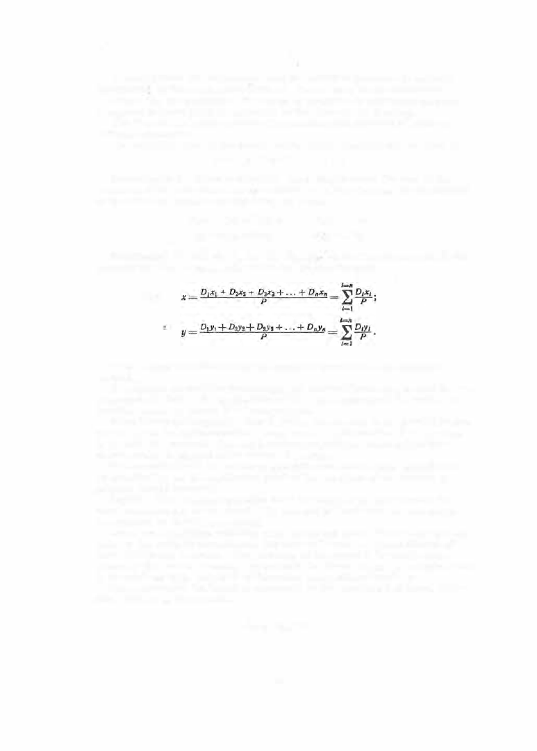
Gene rally,  the  position  of  the  center  of  press ure  is  expressed as 

and 

relative  to  some point of  reference  in  the  plane  of the  drawing. 

The  diagram  in Figure  6  shows  the  simultaneous  piercing of holes  of 

different diam eters . 

The  resultant 

of  all  the  forces  acting during blanking will  be  e qual  to 

P = P1 + P, 

Pa + ·  

. .  

+ P,.. 

Reso rting to  the  theorem  of s tatics ,  according to  which the  s um  of the 

moments  of the  component forces  relative  to  an axis  is  equal  to  the  moment 
of the resultant  relative  to  this  axis ,  we  obtain 

P1x1 

P1x2 

P8x8 

. .

+ P,x,. = P ·x, 

P1Y1  + P2Y2 + PaYs + · · · + P,yn = 

p .y. 

Substituting 

P1,  P2 ,  P3,  P,. 

for 

D1 ,  D2 ,  Da•  D,. 

(or the  perimete rs 

U1 

for 

contours  of  other shapes ),  we  obtain the  general  formula 

This  m ethod  for  determining the  c enter  of p ressure is  an  analytical 

m ethod . 

graphical  method for determining  the  center  of  pressure is  also  in us e .  

I t  c onsists  in  finding the  application p oint of the  resultant o f  the  system  of 

parallel  forces  by  means  of  a  forc e  polygon. 

When blanking irregularly  s haped p arts ,  the  contour of the part  is  b roken 

up into  parts  (straight  segments ,  arc s ,   etc . ) .   Each s ection of the  contour 

is  treated  as  a  material  line and  a  vector proportional  to its  length  (to  a 

chosen  s cale )  is  applied  at its  center  of  gravity . 

The  coordinates  of  the  center  of  p ressure  are  determined,  analytically 

or  graphically,  as  the  application point of  the  resultant  of  the system  of 

parallel forces  ( vectors ) .  

Layout. 

The blanking  operation must  be  designed s o  a s  to ensure  the 

most economic  us e  of the  m etal .  To  that  end the  part  must be laid  out in 

the  strip  so  as  to  minimize  scrap . 

Scrap  resulting from  punching small  holes  and  was te  of  the  m etal  at  both 

ends  of  the  strip  is  unavoidable ,   but  their influence  on  the  coefficient  of 

m etal  utilization is  small .  The  economy of the  layout  is  basically  deter­

mined by the  amount of s c rap  left between the blanks  which,  in certain  cas e s ,  

i s  a s  much a s   7 0 "/o,  only  3 0 "/o  o f  the  meta.l  being utilized us efully. 

The  economy of the layout  is  m easured by  the  coefficient  of m etal  utiliza­

tion,  defined by  the  formula 

km. u.= rr 

1 00, 

6 1  

FIGURE 

7 .   Examples of strip layout 

6 2  

where 

km. u.= 

coefficient  of m etal utilization,  o/o; 

blank area,  mm 2; 

B  = 

s trip  width,  mm; 

strip  feed per blank,  mm  (distance  between two homologous 
points  of two  adjacent blanks ) .  

S everal  examples  o f  layout a r e  shown i n  Figure  7 .   Figure  7,  a  shows  a 

single-row strip  layout,  as  us ed in  blanking  and  s imultaneous  piercing the 

winding wheel  of wris twatches .  The  coefficient  of  metal  utilization  (ne­
glecting the  waste  due to  the  punching of the  holes )  i s  5 0 % .  

Figure  7 ,   b  shows  a  two - row strip  layout used f o r  blanking  spoked  wheels . 

The  coefficient  of m etal  utilization is  6 4  

o/o. 

Figure  7 ,   c  pres ents  a  five - row 

s trip layout for blanking hexagonal  nuts  with  simultaneous  punching of  holes . 

The  blanks  are  arranged in  a  honeycomb pattern  and  the  coefficient  of  metal 

utilization is  6 0 o/o .

Figure  7 ,   d  shows  a  two - row strip  layout for

blanking cas e  rim s ,   with 

simultaneous  punching of holes .  The  layout  is  economical  fo r  the  given 

part,  although  the  coefficient  of metal  utilization is  only  3 3  o/o .  

I n  Figure  7 ,   e  three strip layouts  for blanking alarm - clock  regulators 

are  shown .  The  coefficient  of metal utilization is  32 o/o  in  the  first layout, 

4 0 o/o  in the  s econd,  and  4 6 o/o  in the  third. 

FIGURE 8 .  

Blanking of two parts by  two 

stamping dies from the  same  strip 

Figure  8  shows  the  strip  layout  for 

blanking two  different alarm - clock parts 

in two  different s tamping  dies:  the  re­

gulator is blanked  after the  blanking of 

the  spring. 

The  staggered multi- row layout is 

most  expedient for blanking round parts 

(washers ,  wheels ,   etc . ) .   It should be 

kept in mind,  when designing the l ayout, 

that in mas s  p roduction  a  saving  of 

several  grams  of metal per part adds  up  to  tens  of tons  of metal . 

The  strip  layouts  can  be  designed in the  following m anner:  the  part  is 

cut out of cardboard  in several  copies ,  in its  full - size  dim ensions  or to 
s cale .   Various  arrangements  are  then  tried,  and  the  arrangement  giving 

the  smallest loss of material  is  selected.  If  the  c onfiguration of the part 
is  such  that  there  is  always  considerable  s c rap ,  it  s hould  be  matched with 

another part of the  same thicknes s  and  the  two  parts  can  either be  made  by 
the  s ame  die  or  s eparately by  two  dies . 

A  l ayout  without  s c rap  is  possible  for certain parts  whose  contours  are 

made up  of straight  lines . 

For parts  with  very  narrow sections ,  such as  clock hands ,  etc .  ,  an  in­

vers e  layout  can be used,  in which  the part  remains  in the strip  in the fo rm 

of  a bridge  while  the  blanked  spaces between  the  parts  constitute  the  scrap . 

The  coefficient of m etal  utilization  in  such cases  d rops  to  1 5 - 2 0 o/o .  

The  s trip  layout for blanking wris twatch  hands  i s  shown  in Figure  9 .  

The  thickness  in section a - a  is  equal  to  0 . 1 5 m m ,   and  the  width  is  0 . 0 5  to 

0 . 08 m m .  

The  stamping o f  this  part  is  carried out  as  follows :   the  hole i s  pierced, 

the contour is  blanked;  the central  s ection is  cambered and the  s ocket  drawn; 

lastly,  the  hand  is  cut off from  the  lateral  edges  of the  strip . 

In  designing  the  layout  it  is  necessary  to  take  into  account  the  arrange­

ment  of the parts  relative  to  the  direction of the ( rolling] grain in the material 

6 3  

The  grain  in strips  is  .usually  of  longitudinal  orientation but  if  the  strips 

are  cut  from  sheets  it is  possible  to  obtain trans versally  oriented  grain. 

There  are parts  which,  due  to  their configuration,  cannot  be  made with 

trans versally  directed grain .  The  s top -watch  spring is  an  example  (Figure 

1 0 );  it will  break after heat treatment if  m ade with  trans vers e  grain.  In 

s uch  cases  it  is necess ary  to arrange the parts  along the  s trip,  although 

s uch a  layout  is  less  economical . 

0.05-0.08 

1st 

2nd 

3rd 

4th operation 

FIGURE 9. 

Layout for the blanking of wrist-watch hands 

FIGURE 1 0 .  

Stop-watch spring 

When designing  the  layout  it  is  necessary  to  take  into  account  the  exis t­

ing as s ortment o f  s tandard s trips  (GOST).  If a  c e rtain layout calls  fo r 

s trips  of  nons tandard width,  it  is  likely that  the  extra cost of  p reparation 

of nonstandard  s trips  will be  higher than the economy  achieved  by the  better 

layout.  The  striving for  economy in the layout must not be allowed to lead 

to an increase in m achining work  and to the  introduction of additional  oper­
ations . 

Blanking  of  s heets  or  s trips  leaves  in  the  blank p ortions  of  metal  called 

bridges  which  constitute  waste .  The  width  of  these  bridges  depends  on 

many  factors ,  but  mainly  on  the  s trip  thickness  and  the  metal  s trength . 

It  is  also  influenced  by  the  dimens ions

and  configuration  of  the  blanks , 

the  m eans  of  strip  feeding,  the  required  accuracy,  and  the  s tamping­
die  design .  

The  width o f  the bridges i s  determined using empirical  graphs (Figure 1 1 )  

o r  tables . 

The  data  given  in  Figure  1 1  must b e  multiplied by the following coeffi ­

cients ,  depending  on  the  mate rial  being s tamped:  0 . 9  for s teel  of  average 
hardness,  1 . 0  for hard steel,  1 . 2  for s oft b ras s ,   1 . 4  for aluminum . 

If an  automatic  roll feed is  used in  the  blanking p roces s ,   the  bridge 

values  are  multiplied by  1 . 2 .  

I f  the  blanks  are t o  b e  p ress ed back into  the  s trip,  the  bri dge  width  must 

be inc reas ed by 2 0 o/o . 

Scrap  width 

a� 

at the s trip  edges  is  taken as  equal  to  1 . 2 - 1 . 5 a1 • 

Elements  of  blanking  dies . 

Most s tamping operations  in watch production 

are  conducted  on die  s ets  p rovided with guidepins .  A  die  s et  cons ists  of the 

uppe r  and  lower  shoes ,  the  punch,  the  die,  and  other  auxiliary  components . 

The  shoes  are  two  cas t-iron plates  on  which  all  the  other components  of 

the  die  are mounted .  The  guidepins  and  the  die  block are mounted  on  the 

lower shoe,  the  punch  and  the s hank,  on the upper s ho e .  

6 4  


Content   ..  14  15  16  17   ..