Technology of watch production - part 15
 

  Index      Books     Technology of watch production (Tarasov) 1964 year


Search            


Content   ..  13  14  15  16   ..


Technology of watch production - part 15


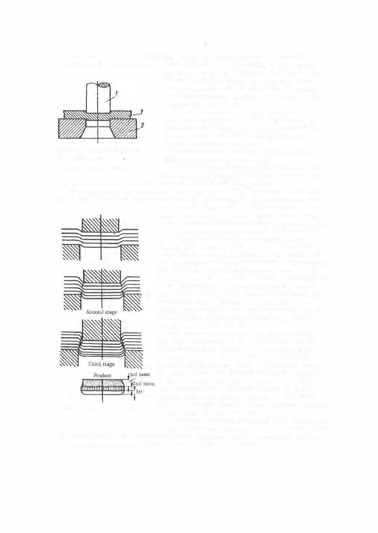
S e c o n d   s t a g e .   During  this  stage,  in which  stres s es  go  beyond  the 

elas tic  limit,  there  occurs  a  further bending and  stretching of  the  fibe rs , 

FIGURE 

1 .  

Schematic diagram of 

the  blanking process 

and  they  are  cut  by  the  s harp  edges  of  the  die .  

A t  the  end of this  s tage ,  the  stres s es  reach 

the ultimate shearing s trength for the m etal, 

and  mic rofractures  appear.  The  press  force 

reaches its  m aximum . 

T h i r d   s t a g e .  The  beginning of  this 

s tage is  characterized by the  app earance  of 

macrofractures  near  the  cutting edges  of  the 

die  and punch,  and  their propagating  at  a 

definite  angle  into  the  m etal . 

These fractures  develop  s wiftly,  and  the 

blank s eparates  from  the  strip . 

1- punch;  2-die;  3-stock. 

If the  clearance between  the punch and  the 

die  opening is  normal,  the punch-side and  die­

side  fractures will  meet  and form  a  common  sh'earing surface .  

I f  the  clearance i s  too small ,  the  di rections o f  the fractures  d o  not  coin­

cide,  and  the double s hearing causes  the  formation of  an extended burr on 

the p roduct  (Figure  3 ) .   If the  clearance is  too 

First stage 

large ,  the  blank  will  have  rugged edges  owing 

to  the  tearing of m aterial  in  the  clearance  spac e .  

A  graph  showing the  s tres ses  i n  the  m etal 

as  a  function of the  ram  motion is  given  in 

F igure 4  for a  steel  strip  of up  to  4 mm  thick­

ness  and of  average  hardness .  The  s ector A B  
corresponds  to  the s tage  of  elastic  deformations 

and  BC  to  the  plastic  deformation s tage  (up  to 

the beginning of shearing).  Point  C  corresponds 

to  the  m aximum  s tress  imposed on the  metal 

during  the blanking and  s ector  CD  indicates  the 

rupturing  stage .  Secto r  DE  gives  the  force 

which must be  applied in order to  ove rcom e  the 

friction when  the  part  is  ejected  from  the  strip 

and forced through  the  die .  

The  three  zones  o n  the late ral  s urface of 

the  part  correspond  to  the  three  stages  of  the 

blanking p rocess  (Figure  2 ).  The firs t  zone, 

corresponding  to  the  first  stage,  is  slightly 

rounded  off  on the  die  side .  The  s econd  zone 

is  a  cylindrical belt formed during the  cutting 
of  the  fibers  by the  cutting edges  of the  die, 

zone 

and  corresponds  to  the  ram  motion up  to  the 

appearance  of  shearing fractures .  The  third 

FIGURE 2.  Stages of the blanking 

zone  is  a  rough conical  surface  and  corresponds 

to  the  stage  of metal  failure . 

process 

Clearance  between  punch  a

nd die .  Clearance 

is  the  diffe rence between the  matching punch and 

die  dimens ions .  The  magnitude  of  the  clearance  required  depends  mainly 

on  the  material  and  the  thickness  of the  part  to  be  blanke d .  

5 7  

Each material  and  thicknes s  have  their optimal  clearance ,   defined as 

the  clearance  for  which the  directions  of the  shearing s tresses  from  the 
punch  and the  die  coincide,  and for which  the  blanking  force is  a  m inimum . 

FIGURE  3.  Shearing fractures  and 

shape of the  blank  in the case of 
insufficient punch clearance 

P,k 

3500 

3100 

2800 
2400 
zooo 

1500 

1l00 

BOO 
�00 

a4  0.8  11  tG  lO 

ZA 

l.B 

.U J.6 

mm 

Ram stroke 

FIGURE 4,  Graph of the stresses in the stamped 
metal as a function of the ram stroke (steel strip 
of a thickness of up to 4 mm and average hardness) 

Despite  the  wide  application  of  blanking operations ,  as  yet  the re  exists 

no  theoretically s ubstantiated  method for determining the  clearanc e .   Em ­

pirical  data are us ed in production practice .  

Recommended clea rances  between the  punch and  the  die  for blanking dies 

are given in Table  1 .  

TABLE  1 

Bilateral clearance between punch and die  in 

o/o 

of the  strip thickness 

Clearance, 

o/o 

Strip thickness,  mm 

brass and mild 

steel of average 

hard steel 

steel 

hardness 

0.1 o- 1  

1 .1 -2 

4.5 

2 .2 -4 

1 0  

4.2 - 6  

12 

Optimum clearances  vary between  5  and  1 2 %  of the  strip  thickness .  

The  values  given are  s uitable  for circular blanks .  When blanking parts 

of a  more  complex shape,  having s harp  angles ,  the  data  given in  the  table 

mus t  be adjusted up  or down,  depending on the  actual  s hape  of the  part. 

In blanking operations  the required clearance  is  obtained at the  expense 

of the  punch  size,  the  size of the blank being  equal to the die  opening.  In 

piercing operations ,  on  the other hand,  the  clearance is  achieved by in­

c reasing the  size  of the die  opening,  as  the size of the pierced hole is  equal 

to  the punch  diam eter .  

1174 

5 8  

Blanking Forces 

The  force 

P ,  

required to  blank  out  a  part,  depends  on  the  shear  area , 

equal  to  the  perimeter  of  the  blanked part  multiplied by  the  stock thickne s s ,  
and  on the s hear strength of the  metal . 

The  force 

is  calculated using the  formula 

where 

the  force,  kg; 

length  of the part perimeter,  mm; 

s  = 

the  thickness  of  the part,  mm; 

a ,  

the  shear s trength of the  metal,  kg/ m m2 . 

For circular parts 

rrD , 

and  ( 1 )  becomes 

P = 'lt· D · S ·a , . 

( 1 )  

If several punches  operate  s imultaneously in the  stamping die,  the  value 

of the  total force 

is  e qual  to  the  s um  of the  forces  calculated s eparately 

for  each punch. 

In a  gang blanking  die  the  blanking force is  sometimes  reduced by instal ­

ling the punches  a t  different heights ,  which  ensures  progressive blanking. 

The  value  of 

a, 

for  various  m aterials  can be found in the  handbooks  on 

stamping.  The  value  of 

als o  depends  on the  die  design.  If the die  hole 

has  a  cylindrical portion,  an  additional  force Q  is  necessary  in  order to 

force the  blankJ  through the  die  (cf.  below).  The  n  mber  of parts  held in 

this  cylindrical  portion obviously depends  on the  height  of the  latter  and  on 

the  thickness  of the  material .  The  force Q  necessary for forcing  through 

one part  is  on  the  average  3  to  5 

"'o 

of 

P .  

If the  die has  a  tapered hole  ( see 

below),  the part will  not be  retained,  and no  additional  force is  needed to 

force it  through . 

The  magnitude  of 

decreases  if  the  strips  are lubricated  and  increas es 

with a  decreas e  in the clearance  between the punch and die below the  normal 

value .   Blunted  cutting  edges  on  the  punch  and  die  als o  inc reas e  the  force. 

decreas es by 5  to 7 

o/o 

when the  strips  are lubricated,  and  can increase 

by  1 5  to  2 0 "/o  with  a  decrease in  the  clearance.  The  blunting of  the  cutting 

edges likewise  leads  to  an  increas e  in 

of  1 0  to  1 5 "/o .  The p res ence  of 

buffer springs  in the  die also  increases  the  required blanking forc e .  

Owing t o  the  above-listed factors ,  the  actual  value  of the blanking force 

is  higher by 20 to  3 0 "/o  than the value  calculated by  ( 1 ): 

J?.cr= 

( 1 . 2  - 1 .3) 

calc 

( 2 )  

Example  of  calculation  of 

P .  

Let the  part  be  a  watch plate:  the  blanking 

diameter,  38 mm;  the thicknes s ,   3 . 2  mm; the material ,  brass; 

" ,  

40 kg/mm2 . 

Atct= 1 .2�tDsa 

s  = 

1 .2 · 3.14·38 · 3.2 · 40 ""  18.!l 

t. 

Center of pressure  of the  die . 

The  blanking forces  are applied  along 

the  cutting edges  of the punch  and  die  and  are  mutually parallel  and per­

p endicular to the  die plane . 

The  point  of  application  of  the  resultant  of  all  the  forces  acting  during 

the  blanking is  called the  c e n t e r  o f   p r e s s u r e . 

59 

The  center  of  pres sure  of  a  blanking  die  mus t  coincide  with  the  axis  of 

the die  shank  mounted  in  the  ram , as  otherwis e,  lateral  shearing forces 

will  appear which  can lead to uneven wear of the ram guides  o r  of the die , 
uneven blunting of  the  cutting edges  and,  in  the  cas e  of s mall  clearances , 

even  punch breakage  or  damage  of  the  die. 

In round parts  the  center  of pressure coincides  with the center  of  the 

blank .  In parts  of  regular  geometrical  shape,  s uch  as  s quares  and  rectan­

gles ,  the  center  of pressure  coincides  with the  inte rs ection of the  diagonals . 

In parts  of  any  shape  the  cente r  of  pressure  will  always  be  located  at 

the  center of gravity  of the  contour of the  part,  calculated by  as sumin g  that 
the  contour of  the part  to  be blanked  is  a  material  line  poss essing weight . 

The re  are s everal  methods  for  the  determination  of  the  center  of  p res ­

sure. 

A  diagram  of the  simultaneous  piercing of two holes of different diam eters , 

having  cente rs  located  on  the  X-axis ,  is  s hown  in  F igure  5,  where  the  fol ­

lowing  designations  have  been  adopted: 

D1 

diam eter of  the  s maller hole; 

D2 

diameter of the larger  hole; 

U1 

and 

U2 

perimeters  of the holes; 

a, = 

shearing  strength . 

The  forces 

P1 

and 

P2 

neces sary for piercing  the  two  holes,  respectively, 

will be  equal to 

P1 = U1s · a, , 

P2 = U2 · S ·a, . 

The  forces 

P1 

and 

P2 

are applied at  the  centers  of  the  corresponding 

circles . 

Pt 

and 

P2 

are  parallel  and  the  magnitude  of  their  resultant  is  the re ­

fore  equal  to  their  sum 

The  point  of application  of  the  resultant 

is  determined by s etting  the 

moments  of  the  two  forces  equal 

Pzl 

X =  

P1 

Substituting fo r 

P. 

and 

P2 

their values  and  canceling 

s ,   a , ,  7t ,  

w e  obtain 

X =  

Dz . 

FIGURE 

5. 

Determination of the  center 

of pressure for  a  two-punch  die 

FIGURE 

6. 

Determination of the  center  of  pressure  for  a 

multi -punch die  by  the  analytical  method 

6 0  


Content   ..  13  14  15  16   ..