Technology of watch production - part 13
 

  Index      Books     Technology of watch production (Tarasov) 1964 year


Search            


Content   ..  11  12  13  14   ..


Technology of watch production - part 13


metals  of  hardness  beyond 

HRc 

6 7 .   The working  range  of  scale 

lies 

within the limits 

HRa 

25  and 

HRa 

1 0 0,  and  of s cale 

between  the  limits 

HRc 

2 0  and 

HRc 

7 0 .  

Diameter of 

imprint 

2.4 

2.45 

2.50 
2.55 

2.60 

2.65 

2.70 

2.75 

2.80 

2.85 

2.90 

2.95 

3.00 

3.05 

3 . 1 0  

3 . 1 5  

3.20 

3.25 

3.30 

3.35 

3.40 

3.45 

3.50 

TABLE  12 

Brinell hardness numbers (P= 3000 

kg, 

Dball 

10 mm) 

Diameter of 

Diameter of 

Hardness n8 

imprint 

HardnessH 8 

imprint 

652 

3.55 

293 

4.70 

627 

3.60 

286 

4,75 

600 

3.65 

277 

4.80 

578 

3.70 

269 

4.85 

555 

3.75 

262 

4.90 

532 

3.80 

255 

4.95 

5 1 2  

3.85 

248 

5.00 

495 

3.90 

241 

5.05 

477 

3.95 

235 

5 . 1 0  

460 

4.00 

229 

5 . 1 5  

444 

4.05 

223 

5.20 

430 

4 . 1 0  

2 1 7  

5.25 

5.30 

4 1 8  

4 . 1 5  

2 1 2  

5.35 

402 

4.20 

207 

5.40 

5.45 

387 

4.25 

202 

5.50 

375 

4.30 

1 96 

5.55 

364 

4.35 

1 92 

5.60 

351 

4.40 

1 87 

5.65 

340 

4.45 

1 83 

5,70 

332 

4.50 

1 79 

5.75 

321 

4 .55 

1 74 

5.80 

5.85 

3 1 1 

4.60 

1 70 

5.90 

302 

4.65 

1 66 

5.95 

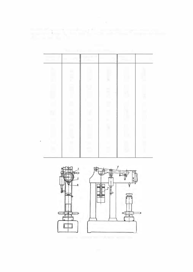
FIGURE 

6. 

Apparatus used for RockHell  hardness tests 

49 

Hardness n8 

1 63 

159 

1 56 

1 53 
149 

1 46 

143 

1 40 

1 37 

1 34 

131 

1 28 

1 26 

124 
1 2 1  

1 1 8  

1 1 6  

1 1 4  

1 1 2 

1 09 

1 07 

1 05 

1 03 

1 0 1  

99 

97 

Rockwell  tests  take less  tim e  than  do  B rinell  tests . 

A nother advantage  o f  the  Rockwell m ethod is  that  the  specimen surface 

suffers  almost no  damage,  the indentations  made by the steel  ball  or the 
diamond indenter being negligible .  

The  Rockwell  hardnes s  tes ter i s  s uitable  for testing specim ens  of a 

thickness not less  than  1 mm  on scale 

C ,  

and  not  less  than  2 mm  on  s cale 

B .  

TABLE  1 3  

Rockwell-hardness scales 

Symbol 

Indenter 

Initial load, 

Final load, kg 

Application 

kg 

Diamond cone with 

apex angle 120' and 

Hard and heat-treated 

1 0  

1 0 + 140 = 150 

of radius curvature 

steels 

0

.

2

mm 

Superhard  alloys,  prod-

The same 

1 0  

10 + 50 =  6 0  

ucts with case-hardened, 

work-hardened surface, 

etc. 

Steel ball  of 1 .588 mm 

diameter 

1 0  

1 0 +  90 =  100 

Soft metals 

Thinner specimens  are  deformed through  the  revers e  side,  and  the 

hardness  readings  are distorted. 

The  Rockwell hardness has a  relative  value,  and is  not an abs olute 

quantity.  One  division on the  indicator  s cale  corresponds  to  a  depth  of 

penetration of 

fl. .  

A  definite  relationship  exists  between the  hardness  values  obtained by 

the Brinell  method and thos e  obtained by the  Rockwell  m ethod  (Figure  7 ). 

As  the  machinability of a  m etal  is  not uniquely determined by its  chemical 

composition  and  m echanical p roperties,  the  m etals  to  b e  us ed in  the  manu­

facture of parts  are  s ubjected to  technological tests . 

D r a w i n g   t e s t   o f   s h e e t  m e t a l s .   Sheets  and  s trips  intended for 

drawing are  s ubjected to  this  test. 

The test  specimen  ( 1 )  is fastened to  the  apparatus  (Figure  8 )  by m eans 

of the  threaded sleeve  ( 5 ).  When  the  hand wheel 

( 7 ) 

is  turned,  the spindle (4 ) 

is  displaced forcing  the  punch  (2 )  into  the  m etal .  The  m etal  is  thus  drawn 

through  the  die  ( 3 )  until c racks  appear.  The  punch and  die  are .of  s tandard 

form ,  and the appearance  of  c racks  is  obs e rved through the mirror 

(6 )

.  The 

depth of draw up  to  the  appearance of c racks  s e rves  as  a  m esure of the 

d rawability of the  m etal . 

Figure  9  presents  three photographs  of  tested specimens .  In  Figure  9,a, 

the  depth  of draw,  for  a  thick b rass  specimen,  was  1 2  m m .   Figure  9,  b 

s hows  a  0 . 3 5  mm  specimen d rawn  to  a  depth  of  5 m m .   In  Figure  9 ,  c ,   a 

0 . 5  mm  steel  specimen  has  b een  drawn  to  a  depth o f  1 0  m m .  

Strip  material  (steel ,  bras s ,   etc . ),  which i s  t o  go  into  the m anufacture 

of alarm - clock case s ,   airborne  clock  housings ,  etc . ,  is  first  subjected  to 

a  drawing test. 

50 

A  drawing depth  of  1 1  to  1 2  mm  has  been  established as  the  standard for 

1 Kh 1 8N9 stainless  steel,  used in the  m anufacture  of lids  and bottoms  for 

pocket- or wristwatches .  

The  conditions  under which  the  drawing tests  are  to b e  carried  out are 

specified by GOST 5 0 3 - 4 1 .  

R e p e a t - b e n d i n g   t e s t s  for  round  and  s quare bars  are  carried  out 

on the  NG- 1 - 2  apparatus  (Figure  1 0 ). 

The  apparatus  consists  of a  s mall  bench- type  vis e  ( 1  ),  with  exchangeable 

jaws  (2 ),  which clamp  one  end of the  specimen.  The  other  end is  held  by 

the  carrier  (4 )  of  the  rotating lever ( 3 ) .  

Hs 

k

g/

mm� 

100 

fSO 

200 

500 

550 

600 

850 

700 

750 

800 

-10 

10 

20 

JO 

40 

50 

SO  10 

Rockwell hardness  scale C 

FIGURE 

7 .   Relationship between Rockwell  and  Brinell 

hardness values 

The  test specimen is  bent  9 0°  alternatingly to  the  right  and  left .  The 

number of  bends  to  failure  of  the  test specimen is  characteristic  of  the 

ductility  o f  the  m etal . 

5 1  

FIGURE 8.  Apparatus for drawing tests 

FIGURE  9.  Drawing test specimens 

FIGURE 10.  NG-1-2 apparatus for bending tests 

52 


Content   ..  11  12  13  14   ..