Technology of watch production - part 18
 

  Index      Books     Technology of watch production (Tarasov) 1964 year


Search            


Content   ..  16  17  18  19   ..


Technology of watch production - part 18


This  die  operates  with  two  side  cutters .  A  general  view  of  the  die is 

shown in F\gure  1 9 .  

The  die has  no  guidepins ,  punches  being guided by the  s tripper  ( 1 )  which 

is  mounted on the  die  (2 ).  In order to  increas e  the  durability  of the  die, 

FIGURE 

1 7 .  

Model Sh-02  blanking die with 

fixed-type  lm"er stripper 

hardened bushings  ( 3 )  are  p ressed into 

it.  The piercing and blanking punches 

(4 )  and  ( 5 )  and  the  side  cutters  ( 6 )  are 

fastened  to the  upper shoe.  The  punches 

neve r  leave  the  guiding stripper  ( 1 )  dur­

ing the  operation  of the  die .  

Progressive  dies  are o f  a  much  s im ­

pler  design  than  are compound  die s .  

C o m p o u n d   d i e s   are us ed for blank­

ing parts  with windows  and  holes  where 

an  accurate  mutual location of  the  holes 

and  the  contour is  required. 

Compound dies are  widely used in 

watch  m anufacture,  as  they m ake it pos ­

s ible  to  blank parts  to  a  high  degree of 

accuracy  ( 0 . 02 mm ) .   Their s hortcom­

ing lies in the complexity of their design 

and  manufacture . 

A  schematic  drawing of  the model 

Sh- 04  compound  die  for  blanking a  round 

part  with a  hole  is  shown  in  Figure  2 0 .  

When the  uppe r  die i s  lowered,  the 

s tock is  pressed onto  the  lower die. 

The spring s trippe r  (4 )  des cends  s imul ­

taneously with the upper die ,   the blanking 

punch  ( 5 )  and the  die  ( 3 )  blank  the  part, 

and the knock- out  (6 )  is  pushed back. 

At  the  same time  the piercing punch (2 ), 

cooperating with the hole in  the blanking 

punch  ( 5 )  which  constitutes  a  die, pierces 

a  hole in the part.  When the upper die 

is  lifted,  the s tripper (4 )  removes the stock from the blanking punch  (5 ), 

while the knock- out  ( 6  ),  actuated by the push pin  ( 1 )  and the spring  ( 7  ), ejects 

the blanked p art from  the  die  ( 3 )  and forces  it back into the  s trip . 

The  model  Sh- 06  compound  die  for blanking b rass  wheels  is  s hown  in 

Figure  2 1 .  

The  blanking punch  ( 6 - 7 )  is  mounted in the lower shoe  of this  die  and 

s erves  als o  as  piercing die  for  both the  s ector windows  and  the  central  hol e .  
The  punch is  compos ed of the  contour punch  (Figure  2 2 ,  a )  and the  core 

(Figure  2 2 ,  b ),  clamped together by the ring ( 5 )  (Figure  2 1 ).  The s tock 

s trippe r  (4 )  is  also mounted in the  lower shoe. 

The  die  ( 3 )  for blanking the external  contour of the part,  and the  punch (2 ) 

for blanking  the s ector windows ,  are  mounted  in the upper s ho e .   The  punch 

(2 )  consists  of five  s ectors  (Figure  2 3 ).  The punch  ( 1 )  (Figure  2 1 )  for 

pie rcing  the central hole,  and  the  knock- out  ( 8 )  for p ressing  the  part back 

in

t

o the s trip ,  are  also mounted in the upper s ho e .  

6 9  

.....] 

FIGURE  1 8 .   Strip  layout  of  alarm-clock  pawls for  stamping  on  a 
progressive  die 

_ _  

ij3 

__ _ _ _  

_ _  - - - - - - - -

-

t.- t+ 

----- - - - - --

- - - - �

o

- - - -

I._ 

_ _  

_) 

-· 

FIGURE  1 9 .   General  view  o f  a  progressive  die 

FIGURE 

2 0 .   Sh- 04  compound  blanking die 

FIGURE 

2 1 .  

Sh-06 compound die  for  blanking 

wheels with tapering spokes 

FIGURE 

22.  Lower  punch : 

a-contour  punch;  b-punch  core . 

7 1  

The  knock- out  ( 8 )  (Figure  2 4 )  c onsists  of  the  knock- out p roper ( Figure 

24,  a),  and  the  star- s haped  core  (Figure  2 4 ,   b ) .  

The  working parts  o f  the  die  set  are  standardized.  The  dimens ions  of 

the  upper and lower punches  mounted in the die  s et  No. 

are  given  in 

Figure  22 

-

2 4   (see Table  2 ) .  

FIGURE 23.  Upper puncl1 for  punching 
\V indows 

FIGURE 

24. 

Knock-out of a sectional die : 

a-knock-out proper;  b-core. 

The  stamping die  operates  as  follows :  when  the  upper shoe  is  lowered, 

the punch  (6 - 7) p enetrates  into the die ( 3 )  and blanks  the part.  The strip ­

per  (4 )  goes  down.  The  knock- out  ( 8 )  is  forced up  and  compress es  the 

spring through  a  pin  and  washer.  Simultaneously,  the  punches  ( 1 )  and  (2 ) 

p roduc e  the  s ector  windows  and  the  central hole.  Slugs  from  the holes  d rop 

through  a  hole in the  lower  shoe  and the bols ter plate into  a  box.  When the 

uppe r  shoe  returns ,  the  blanked p art is  ejected by the  knock- out  ( 8 ),  the 

stock is  removed  from  the  punch  (6  - 7 )  by the  s trippe r  (4 ),  and the  part  is 
forced back  into  the  strip . 

Parts  punched by  this  m ethod  have  no  rough  edges  and  do  not  require 

any  additional  straightening.  They need only be pres sed out of the  strip , 

a  very s imple  operation.  For s table  operation all  parts  of  the  die  s et  s hould 

have  proper fits  and should be  centered. 

Hardened s teel  dis ks  are placed between the contact faces of the  cas t ­

iron  shoes and the die block in order to p rotect the  shoe  against local  denting. 

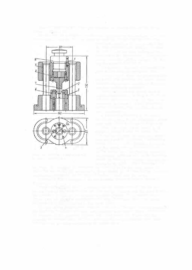
P i e r c i n g   d i e s   are  a  variant  of the blanking dies .  They are  used  for 

piercing holes  in blanked parts  located in  the  die by  their  external  contour. 

A  piercing die for piercing a  central  hole  in gears  located  acco rding to 

their external  diameter is  s hown  in  Figure  2 5 .  

The  gear is  ins e rted  into  the  conical  part o f  the  c entering nes t  ( 6 ) .  The 

die  ( 8 )  is  mounted  on the  upper shoe and  the  punch  ( 5 )  in the  punch  holde r ( 1 ) . 

The  centering nes t  ( 6 )  is  free  to  slide  on  the  punch  holder ( 1 )  and  is  held by 

three springs  ( 3 ) .   The  part  to  be  pierced is  put  into  the  centering nes t  ( 6 ). 

7 2  


Content   ..  16  17  18  19   ..