CESSNA 172S NAV III Skyhawk SP. Information Manual (2016) - page 4
SECTION 8
CESSNA
AIRPLANE HANDLING, SERVICE
MODEL 172S NAV III
AND MAINTENANCE
KAP 140 AUTOPILOT
FUEL (Continued)
FUEL ADDITIVES
Strict adherence to recommended preflight draining instructions as
called for in Section 4 will eliminate any free water accumulations from
the tank sumps. While small amounts of water may still remain in
solution in the gasoline, it will normally be consumed and go unnoticed
in the operation of the engine.
One exception to this can be encountered when operating under the
combined effect of: (1) use of certain fuels, with (2) high humidity
conditions on the ground (3) followed by flight at high altitude and low
temperature. Under these unusual conditions, small amounts of water
in solution can precipitate from the fuel stream and freeze in sufficient
quantities to induce partial icing of the engine fuel system.
While these conditions are quite rare and will not normally pose a
problem to owners and operators, they do exist in certain areas of the
world and consequently must be dealt with, when encountered.
Therefore, to help alleviate the possibility of fuel icing occurring under
these unusual conditions, it is permissible to add isopropyl alcohol or
Diethylene Glycol Monomethyl Ether (DiEGME) compound to the fuel
supply.
The introduction of alcohol or DiEGME compound into the fuel provides
two distinct effects: (1) it absorbs the dissolved water from the gasoline
and (2) alcohol has a freezing temperature depressant effect.
NOTE
When using fuel additives, it must be remembered that the
final goal is to obtain a correct fuel to additive ratio in the
tank, and not just with fuel coming out of the refueling
nozzle. For example, adding
15 gallons of correctly
proportioned fuel to a tank which contains 20 gallons of
untreated fuel will result in a lower than acceptable
concentration level to the 35 gallons of fuel which now
reside in the tank.
(Continued Next Page)
8-16
U.S.
172SPHAUS-05
CESSNA
SECTION 8
MODEL 172S NAV III
AIRPLANE HANDLING, SERVICE
KAP 140 AUTOPILOT
AND MAINTENANCE
FUEL (Continued)
FUEL ADDITIVES (Continued)
Alcohol, if used, is to be blended with the fuel in a concentration of 1%
by volume. Concentrations greater than 1% are not recommended
since they can be detrimental to fuel tank materials.
The manner in which the alcohol is added to the fuel is significant
because alcohol is most effective when it is completely dissolved in the
fuel. To ensure proper mixing, the following is recommended:
1. For best results, the alcohol should be added during the fueling
operation by pouring the alcohol directly on the fuel stream
issuing from the fueling nozzle.
2. An alternate method that may be used is to premix the complete
alcohol dosage with some fuel in a separate clean container
(approximately 2-3 gallon capacity) and then transferring this
mixture to the tank prior to the fuel operation.
(Continued Next Page)
172SPHAUS-05
U.S.
8-17

SECTION 8
CESSNA
AIRPLANE HANDLING, SERVICE
MODEL 172S NAV III
AND MAINTENANCE
KAP 140 AUTOPILOT
FUEL MIXING RATIO
Figure 8-1*
8-18
U.S.
172SPHAUS-05
CESSNA
SECTION 8
MODEL 172S NAV III
AIRPLANE HANDLING, SERVICE
KAP 140 AUTOPILOT
AND MAINTENANCE
FUEL (Continued)
FUEL ADDITIVES (Continued)
Diethylene Glycol Monomethyl Ether (DiEGME) compound must be
carefully mixed with the fuel in concentrations between
0.10%
(minimum) and 0.15% (maximum) of total fuel volume. Refer to Figure
8-1 for a DiEGME-to-fuel mixing chart.
WARNING
ANTI-ICING ADDITIVE IS DANGEROUS TO HEALTH
WHEN BREATHED AND/OR ABSORBED INTO THE
SKIN.
CAUTION
MIXING OF DIEGME WITH FUEL IS EXTREMELY
IMPORTANT. A CONCENTRATION IN EXCESS OF THAT
RECOMMENDED (0.15% BY VOLUME MAXIMUM) MAY
RESULT IN DETRIMENTAL EFFECTS TO THE FUEL
TANK AND SEALANT, AND DAMAGE TO O-RINGS AND
SEALS USED IN THE FUEL SYSTEM AND ENGINE
COMPONENTS. A CONCENTRATION OF LESS THAN
THAT RECOMMENDED (0.10% BY TOTAL VOLUME
MINIMUM) WILL RESULT IN INEFFECTIVE TREATMENT.
USE ONLY BLENDING EQUIPMENT THAT IS
RECOMMENDED BY THE MANUFACTURER TO OBTAIN
PROPER PROPORTIONING.
Prolonged storage of the airplane will result in a water buildup in the
fuel which leeches out the additive. An indication of this is when an
excessive amount of water accumulates in the fuel tank sumps. The
concentration can be checked using a differential refractometer. It is
imperative that the technical manual for the differential refractometer be
followed explicitly when checking the additive concentration.
(Continued Next Page)
172SPHAUS-05
U.S.
8-19
SECTION 8
CESSNA
AIRPLANE HANDLING, SERVICE
MODEL 172S NAV III
AND MAINTENANCE
KAP 140 AUTOPILOT
FUEL (Continued)
FUEL CONTAMINATION
Fuel contamination is usually the result of foreign material present in
the fuel system, and may consist of water, rust, sand, dirt, microbes or
bacterial growth. In addition, additives that are not compatible with fuel
or fuel system components can cause the fuel to become
contaminated.
Before each flight and after each refueling, use a clear sampler cup and
drain at least a cupful of fuel from each fuel tank drain location and from
the fuel strainer quick drain valve to determine if contaminants are
present, and to ensure the airplane has been fueled with the proper
grade of fuel.
If contamination is detected, drain all fuel drain points again, including
the fuel reservoir tank and fuel selector drain valves, and then gently
rock the wings and lower the tail to the ground to move any additional
contaminants to the sampling points. Take repeated samples from all
fuel drain points until all contamination has been removed. If, after
repeated sampling, evidence of contamination still exists, the airplane
should not be flown. Tanks should be drained and system purged by
qualified maintenance personnel. All evidence of contamination must
be removed before further flight. If the airplane has been serviced with
the improper fuel grade, defuel completely and refuel with the correct
grade. Do not fly the airplane with contaminated or unapproved fuel.
In addition, Owners/Operators who are not acquainted with a particular
fixed base operator should be assured that the fuel supply has been
checked for contamination and is properly filtered before allowing the
airplane to be serviced. Fuel tanks should be kept full between flights,
provided weight and balance considerations will permit, to reduce the
possibility of water condensing on the walls of partially filled tanks.
To further reduce the possibility of contaminated fuel, routine
maintenance of the fuel system should be performed in accordance
with the airplane Maintenance Manual. Only the proper fuel, as
recommended in this POH, should be used, and fuel additives should
not be used unless approved by Cessna and the Federal Aviation
Administration.
8-20
U.S.
172SPHAUS-05
CESSNA
SECTION 8
MODEL 172S NAV III
AIRPLANE HANDLING, SERVICE
KAP 140 AUTOPILOT
AND MAINTENANCE
LANDING GEAR
Consult the following table for servicing information on the landing gear.
COMPONENT
SERVICING CRITERIA
Nose Wheel (5.00-5, 6-Ply Rated Tire)
45.0 PSI
Main Wheel (6.00-6, 6-Ply Rated Tire)
42.0 PSI
Brakes
MIL-H-5606
Nose Gear Shock Strut
MIL-H-5606; 45.0 PSI *
* Keep strut filled with MIL-H-5606 hydraulic fluid per
filling instructions placard, and with no load on the strut,
inflate with air to 45.0 PSI. Do not over inflate.
172SPHAUS-05
U.S.
8-21
SECTION 8
CESSNA
AIRPLANE HANDLING, SERVICE
MODEL 172S NAV III
AND MAINTENANCE
KAP 140 AUTOPILOT
CLEANING AND CARE
WINDSHIELD AND WINDOWS
The plastic windshield and windows should be cleaned with an airplane
windshield cleaner. Apply the cleaner sparingly with soft cloths, and rub
with moderate pressure until all dirt, oil scum and bug stains are
removed. Allow the cleaner to dry, then wipe it off with soft flannel
cloths.
CAUTION
NEVER USE GASOLINE, BENZENE, ALCOHOL,
ACETONE, FIRE EXTINGUISHER, ANTI-ICE FLUID,
LACQUER THINNER OR GLASS CLEANER TO CLEAN
THE PLASTIC. THESE MATERIALS WILL ATTACK THE
PLASTIC AND MAY CAUSE IT TO CRAZE.
If a windshield cleaner is not available, the plastic can be cleaned with
soft cloths moistened with Stoddard solvent to remove oil and grease.
Follow by carefully washing with a mild detergent and plenty of water.
Rinse thoroughly, then dry with a clean moist chamois.
Do not rub the plastic with a dry cloth since this builds up an
electrostatic charge which attracts dust. Waxing with a good
commercial wax will finish the cleaning job. A thin, even coat of wax,
polished out by hand with clean soft flannel cloths, will fill in minor
scratches and help prevent further scratching.
Do not use a canvas cover on the windshield unless freezing rain or
sleet is anticipated since the cover may scratch the plastic surface.
(Continued Next Page)
8-22
U.S.
172SPHAUS-05
CESSNA
SECTION 8
MODEL 172S NAV III
AIRPLANE HANDLING, SERVICE
KAP 140 AUTOPILOT
AND MAINTENANCE
CLEANING AND CARE (Continued)
PAINTED SURFACES
The painted exterior surfaces of your new Cessna have a durable, long
lasting finish.
Generally, the painted surfaces can be kept bright by washing with
water and mild soap, followed by a rinse with water and drying with
cloths or a chamois. Harsh or abrasive soaps or detergents which
cause corrosion or scratches should never be used. Remove stubborn
oil and grease with a cloth moistened with Stoddard solvent. Take
special care to make sure that the exterior graphics are not touched by
the solvent. For complete care of exterior graphics, refer to the
Maintenance Manual.
To seal any minor surface chips or scratches and protect against
corrosion, the airplane should be waxed regularly with a good
automotive wax applied in accordance with the manufacturer's
instructions. If the airplane is operated in a seacoast or other salt water
environment, it must be washed and waxed more frequently to assure
adequate protection. Special care should be taken to seal around rivet
heads and skin laps, which are the areas most susceptible to corrosion.
A heavier coating of wax on the leading edges of the wings and tail and
on the cowl nose cap and propeller spinner will help reduce the
abrasion encountered in these areas. Reapplication of wax will
generally be necessary after cleaning with soap solution or after
chemical deicing operations.
When the airplane is parked outside in cold climates and it is necessary
to remove ice before flight, care should be taken to protect the painted
surfaces during ice removal with chemical liquids. Isopropyl alcohol will
satisfactorily remove ice accumulations without damaging the paint.
However, keep the isopropyl alcohol away from the windshield and
cabin windows since it will attack the plastic and may cause it to craze.
(Continued Next Page)
172SPHAUS-05
U.S.
8-23
SECTION 8
CESSNA
AIRPLANE HANDLING, SERVICE
MODEL 172S NAV III
AND MAINTENANCE
KAP 140 AUTOPILOT
CLEANING AND CARE (Continued)
PROPELLER CARE
Preflight inspection of propeller blades for nicks, and wiping them
occasionally with an oily cloth to clean off grass and bug stains will
assure long blade life. Small nicks on the propeller, particularly near the
tips and on the leading edges, should be dressed out as soon as
possible since these nicks produce stress concentrations, and if
ignored, may result in cracks or failure of the propeller blade. Never use
an alkaline cleaner on the blades; remove grease and dirt with
Stoddard solvent.
ENGINE CARE
The engine may be cleaned, using a suitable solvent, in accordance
with instructions in the Maintenance Manual. Most efficient cleaning is
done using a spray type cleaner. Before spray cleaning, ensure that
protection is afforded for components which might be adversely
affected by the solvent. Refer to the airplane Maintenance Manual for
proper lubrication of controls and components after engine cleaning.
The induction air filter should be replaced when its condition warrants,
not to exceed 500 hours.
(Continued Next Page)
8-24
U.S.
172SPHAUS-05
CESSNA
SECTION 8
MODEL 172S NAV III
AIRPLANE HANDLING, SERVICE
KAP 140 AUTOPILOT
AND MAINTENANCE
CLEANING AND CARE (Continued)
INTERIOR CARE
To remove dust and loose dirt from the upholstery and carpet, clean the
interior regularly with a vacuum cleaner.
Blot up any spilled liquid promptly with cleansing tissue or rags. Do not
pat the spot; press the blotting material firmly and hold it for several
seconds. Continue blotting until no more liquid is taken up. Scrape off
sticky materials with a dull knife, then spot clean the area.
Oily spots may be cleaned with household spot removers, used
sparingly. Before using any solvent, read the instructions on the
container and test it on an obscure place on the fabric to be cleaned.
Never saturate the fabric with a volatile solvent; it may damage the
padding and backing materials.
Soiled upholstery and carpet may be cleaned with foam type detergent,
used according to the manufacturer's instructions. To minimize wetting
the fabric, keep the foam as dry as possible and remove it with a
vacuum cleaner.
For complete information related to interior cleaning, refer to the
Maintenance Manual.
AVIONICS CARE
The Garmin GDU displays have an anti-reflective coating that is very
sensitive to skin oils, waxes, ammonia, and abrasive cleaners. Clean
the displays as described in the G1000 Cockpit Reference Guide.
172SPHAUS-05
U.S.
8-25/8-26
CESSNA
SECTION 9
MODEL 172S NAV III
SUPPLEMENTS
KAP 140 AUTOPILOT
SUPPLEMENTS
INTRODUCTION
The supplements in this section contain amended operating limitations,
operating procedures, performance data and other necessary
information for airplanes conducting special operations for both
standard and optional equipment installed in the airplane. Operators
should refer to each supplement to ensure that all limitations and
procedures appropriate for their airplane are observed.
A non FAA Approved Log Of Approved Supplements is provided for
convenience only. This log is a numerical list of all FAA Approved
supplements applicable to this airplane by name, supplement number
and revision level. This log should be used as a checklist to ensure all
applicable supplements have been placed in the Pilot's Operating
Handbook (POH). Supplements for both standard and installed optional
equipment must be maintained to the latest revision. Those
supplements applicable to optional equipment which is not installed in
the airplane, do not have to be retained.
Each individual supplement contains its own Log of Effective Pages.
This log lists the page number and revision level of every page in the
supplement. The log also lists the dates on which revisions to the
supplement occurred. Supplement page numbers will include an S and
the supplement number preceding the page number.
The part number of the supplement provides information on the
revision level. Refer to the following example:
172SPHAUS
-S1
-00
Revision Level (Original Issue)
Supplement Number
Airplane Model - 172S
Nav III, KAP 140 Autopilot, U.S.,
(Serials 172S9810 thru 172S10467
and 172S10469 thru 172S10506
and 172S10508 thru 172S10639
and 172S10641 thru 172S10655)
FAA APPROVED
172SPHAUS-05
U.S.
9-1/9-2
CESSNA
SECTION 9
MODEL 172S NAV III
SUPPLEMENTS
KAP 140 AUTOPILOT
LOG OF APPROVED SUPPLEMENTS
NOTE
It is the airplane owner's responsibility to make sure that he
or she has the latest revision to each supplement of a
Pilot's Operating Handbook, and the latest issued “Log Of
Approved Supplements”. This
“Log Of Approved
Supplements” was the latest version as of the date it was
shipped by Cessna; however, some changes may have
occurred, and the owner should verify this is the latest,
most up-to-date version by contacting Cessna Customer
Care at (316) 517-5800.
Supplement
Name
Revision
Equipment
Number
Level
Installed
1
Pointer Model 3000-11 or Model
1
4000-11 Emergency Locator
Transmitter (ELT)
2
Canadian Certified Airplanes
2
3
Bendix/King KAP
140
2 Axis
1
Autopilot
4
Winterization Kit
0
5
Brazilian Certified Airplanes
3
6
Artex C406-N Emergency Locator
1
Transmitter (ELT)
7
Bendix/King KR87 Automatic
0
Direction Finder (ADF)
8
Russian Federation (RF) and
0
Other Commonwealth of
Independent States (CIS)
Countries
9
Artex ME406 Emergency Locator
0
Transmitter (ELT)
10
JAR-OPS Operational Eligibility
0
11
Japanese Certified Airplanes
0
12
Garmin G1000 Synthetic Vision
1
Technology (SVT)
13
Argentine Certified Airplanes
0
14
Reserved
15
Ukrainian Certified Airplanes
0
172SPHAUSLOG-16
9 February 2015
U.S.
Log 1/Log 2
Pilot’s Operating Handbook and
FAA Approved Airplane Flight Manual
CESSNA MODEL 172S
NAV III AVIONICS OPTION
Serials 172S9810 and On
SUPPLEMENT 1
POINTER MODEL 3000-11 OR MODEL 4000-11
EMERGENCY LOCATOR TRANSMITTER
SERIAL NO. _____________________
REGISTRATION NO.________________
This supplement must be inserted into Section 9 of the Pilot's Operating Handbook
and FAA Approved Airplane Flight Manual when the Pointer Model 3000-11 or
Model 4000-11 Emergency Locator Transmitter is installed. The Pointer Model
4000-11 Emergency Locator Transmitter is approved for use only in the USA,
Canada, Japan and France.
25 FEBRUARY 2005
COPYRIGHT © 2005
CESSNA AIRCRAFT COMPANY
WICHITA, KANSAS, USA
REVISION 1
19 SEPTEMBER 2005
172SPHAUS-S1-01
U.S.
S1-1
SECTION 9 - SUPPLEMENTS
CESSNA
SUPPLEMENT 1
MODEL 172S NAV III
SUPPLEMENT 1
POINTER MODEL 3000-11 OR MODEL 4000-11
EMERGENCY LOCATOR TRANSMITTER (ELT)
Use the Log of Effective Pages to determine the current status of this
supplement.
Pages affected by the current revision are indicated by an asterisk (*)
preceding the page number.
Supplement Status Date
Original Issue
25 February 2005
Revised
19 September 2005
LOG OF EFFECTIVE PAGES
Page
Page
Revision
Number
Status
Number
* S1-1 thru S1-2
Revised
1
S1-3
Original
0
* S1-4
Revised
1
S1-5 thru S1-12
Original
0
FAA APPROVED
S1-2
U.S.
172SPHAUS-S1-01
CESSNA
SECTION 9 - SUPPLEMENTS
MODEL 172S NAV III
SUPPLEMENT 1
SERVICE BULLETIN CONFIGURATION LIST
The following is a list of Service Bulletins that are applicable to the
operation of the airplane, and have been incorporated into this
supplement. This list contains only those Service Bulletins that are
currently active.
Number Title
Airplane
Revision
Incorporated
Serial
Incorporated in Airplane
Effectivity
FAA APPROVED
172SPHAUS-S1-00
U.S.
S1-3
SECTION 9 - SUPPLEMENTS
CESSNA
SUPPLEMENT 1
MODEL 172S NAV III
POINTER MODEL
3000-11
OR
4000-11
EMERGENCY LOCATOR TRANSMITTER (ELT)
GENERAL
This supplement provides information which must be observed when
operating the Pointer Model 3000-11 or 4000-11 Emergency Locator
Transmitter. The Pointer Model
4000-11 Emergency Locator
Transmitter is approved for use only in the USA, Canada, Japan and
France.
Both the Pointer Model 3000-11 ELT (which incorporates the English
placard) and Model 4000-11 ELT (which incorporates the bilingual
placard) consist of a self-contained, dual-frequency, solid-state
transmitter powered by a battery pack consisting of five alkaline "C" cell
batteries and is automatically activated by a deceleration sensing
inertia "G" switch, which is designed to activate when the unit senses
longitudinal inertia forces as required in TSO-C91A. Also, a remote
switch/annunciator is installed on the top right hand side of the copilot's
instrument panel for control of the ELT from the flight crew station. The
annunciator, which is in the center of the rocker switch, comes on when
the ELT transmitter is transmitting. The ELT emits an omni-directional
signal on the international distress frequencies of 121.5 MHz and 243.0
MHz. General aviation and commercial aircraft, the FAA and CAP
monitor 121.5 MHz, and 243.0 MHz is monitored by the military.
The ELT is contained in a high impact, fire retardant, fiberglass filled
Lexan case with carrying handle and is mounted behind the aft cabin
partition wall on the right side of the tailcone. To gain access to the unit,
unfasten the turn fasteners on the aft cabin partition. The ELT is
operated by a control panel at the forward facing end of the unit or by
the remote switch/annunciator located on the top right hand portion of
the copilot's instrument panel (refer to Figure S1-1).
Power for the transmitter is provided by an alkaline battery pack inside
the transmitter case.
(Continued Next Page)
FAA APPROVED
S1-4
U.S.
172SPHAUS-S1-01

CESSNA
SECTION 9 - SUPPLEMENTS
MODEL 172S NAV III
SUPPLEMENT 1
GENERAL (CONTINUED)
In accordance with FAA regulations, the ELT's battery pack must be
replaced after 2 years shelf or service life or for any of the following
reasons:
a. After the transmitter has been used in an emergency situation
(including any inadvertent activation of unknown duration).
b. After the transmitter has been operated for more than one
cumulative hour (e.g. time accumulated in several tests and
inadvertent activation of known duration).
c. On or before battery replacement date. Battery replacement
date is marked on the battery pack and the label on the
transmitter.
POINTER MODEL 3000-11
EMERGENCY LOCATOR TRANSMITTER
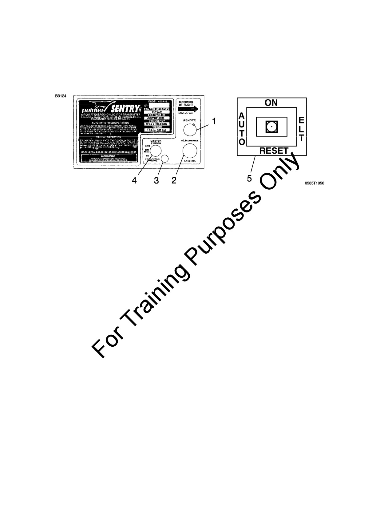
Figure S1-1
1. REMOTE CABLE JACK - Connects to ELT remote switch/
annunciator located on the copilot's instrument panel.
2. ANTENNA RECEPTACLE - Connects to antenna mounted on top
of tailcone.
3. TRANSMITTER ANNUNCIATOR LIGHT - comes on red to
indicate the transmitter is transmitting a distress signal.
(Continued Next Page)
FAA APPROVED
172SPHAUS-S1-00
U.S.
S1-5
SECTION 9 - SUPPLEMENTS
CESSNA
SUPPLEMENT 1
MODEL 172S NAV III
GENERAL (CONTINUED)
4.
MASTER FUNCTION SELECTOR SWITCH (3-position toggle
switch):
AUTO - Arms transmitter for automatic activation if "G" switch
senses a predetermined deceleration level.
ON -
Activates transmitter instantly. Used for test purposes
and if "G" switch is inoperative. The ON position
bypasses the automatic activation switch. (The red
annunciator in the center of the remote switch/
annunciator should come on).
OFF/
Deactivates transmitter during handling, following
RESET - rescue and to reset the automatic activation function.
(The red annunciator in the center of the remote
switch/annunciator should go off).
5.
REMOTE SWITCH/ANNUNCIATOR (3-position rocker switch):
ON -
Remotely activates the transmitter for test or
emergency situations. Red annunciator in center of
rocker switch comes on to indicate that the transmitter
is transmitting a distress signal.
AUTO - Arms transmitter for automatic activation if "G" switch
senses a predetermined deceleration level.
RESET - Deactivates and rearms transmitter after automatic
activation by the "G" switch. Red annunciator in center
of rocker switch should go off.
(Continued Next Page)
FAA APPROVED
S1-6
U.S.
172SPHAUS-S1-00
CESSNA
SECTION 9 - SUPPLEMENTS
MODEL 172S NAV III
SUPPLEMENT 1
GENERAL (CONTINUED)
POINTER MODEL 4000-11
EMERGENCY LOCATOR TRANSMITTER
Figure S1-2
1.
REMOTE CABLE JACK - Connects to ELT remote switch/
annunciator located on the copilot's instrument panel.
2.
ANTENNA RECEPTACLE - Connects to antenna mounted on top
of tailcone.
3.
TRANSMITTER ANNUNCIATOR LIGHT - comes on red to
indicate the transmitter is transmitting a distress signal.
4.
MASTER FUNCTION SELECTOR SWITCH (3-position toggle
switch):
AUTO - Arms transmitter for automatic activation if "G" switch
senses a predetermined deceleration level.
ON -
Activates transmitter instantly. Used for test purposes
and if "G" switch is inoperative. The ON position
bypasses the automatic activation switch. (The red
annunciator in the center of the remote switch/
annunciator should come on).
OFF/
Deactivates transmitter during handling, following
RESET - rescue and to reset the automatic activation function.
(The red annunciator in the center of the remote
switch/annunciator should go off).
(Continued Next Page)
FAA APPROVED
172SPHAUS-S1-00
U.S.
S1-7
SECTION 9 - SUPPLEMENTS
CESSNA
SUPPLEMENT 1
MODEL 172S NAV III
GENERAL (CONTINUED)
5. REMOTE SWITCH/ANNUNCIATOR (3-position rocker switch):
ON -
Remotely activates the transmitter for test or
emergency situations. Red annunciator in center of
rocker switch comes on to indicate that the transmitter
is transmitting a distress signal.
AUTO - Arms transmitter for automatic activation if "G" switch
senses a predetermined deceleration level.
RESET - Deactivates and rearms transmitter after automatic
activation by the "G" switch. Red annunciator in center
of rocker switch should go off.
OPERATING LIMITATIONS
Refer to Section
2 of the Pilot's Operating Handbook and FAA
Approved Flight Manual (POH/AFM).
EMERGENCY PROCEDURES
Before performing a forced landing, especially in remote and
mountainous areas, activate the ELT transmitter by positioning the
remote switch/annunciator to the ON position. The annunciator in
center of the rocker switch should be illuminated.
Immediately after a forced landing where emergency assistance is
required, the ELT should be utilized as follows:
NOTE
The ELT remote switch/annunciator system could be
inoperative if damaged during a forced landing. If
inoperative, the inertia "G" switch will activate automatically.
However, to turn the ELT OFF and ON again requires
manual switching of the master function selector switch
which is located on the ELT unit.
(Continued Next Page)
FAA APPROVED
S1-8
U.S.
172SPHAUS-S1-00
CESSNA
SECTION 9 - SUPPLEMENTS
MODEL 172S NAV III
SUPPLEMENT 1
EMERGENCY PROCEDURES (CONTINUED)
1.
VERIFY ELT ACTIVATION:
a. Position remote switch/annunciator to the ON position even if
annunciator light is already on.
b. If airplane radio is operable and can be safely used (no threat
of fire or explosion), turn ON and select 121.5 MHz. If the ELT
can be heard transmitting, it is working properly.
c. Ensure that antenna is clear of obstructions.
NOTE
When the ELT is activated, a decreasing tone will be heard
before the typical warbling tone begins.
2.
PRIOR TO SIGHTING RESCUE AIRCRAFT - Conserve airplane
battery. Do not activate radio transceiver.
3.
AFTER SIGHTING RESCUE AIRCRAFT - Position remote
switch/annunciator to the RESET position and release to the
AUTO position to prevent radio interference. Attempt contact with
rescue aircraft with the radio transceiver set to a frequency of
121.5 MHz. If no contact is established, return the remote switch/
annunciator to the ON position immediately.
4.
FOLLOWING RESCUE - Position remote switch/annunciator to
the AUTO position, terminating emergency transmissions.
FAA APPROVED
172SPHAUS-S1-00
U.S.
S1-9
SECTION 9 - SUPPLEMENTS
CESSNA
SUPPLEMENT 1
MODEL 172S NAV III
NORMAL PROCEDURES
When the remote switch/annunciator is in the AUTO position and the
ELT master function selector switch remains in the AUTO position, the
ELT automatically activates when the unit senses longitudinal inertia
forces as required in TSO-C91A.
After a lightning strike, or an exceptionally hard landing, the ELT may
activate although no emergency exists. If the remote switch/
annunciator comes on, the ELT has inadvertently activated itself.
Another way to check is to select 121.5 MHz on the radio transceiver
and listen for an emergency tone transmission. If the remote switch/
annunciator is on or an emergency tone is heard, position the remote
switch/annunciator in the RESET position and release to the AUTO
position.
The ELT must be serviced in accordance with FAR Part 91.207.
INSPECTION/TEST
1. The emergency locator transmitter should be tested every 100
hours.
NOTE
Test should only be conducted within the first 5 minutes of
each hour.
2. Disconnect antenna cable from ELT.
3. Set the MASTER switch BAT in the ON position.
4. Turn airplane transceiver ON and set frequency to 121.5 MHz.
5. Place remote switch/annunciator in the ON position. The
annunciator should come on. Permit only three emergency tone
transmissions, then immediately reposition the remote switch/
annunciator to the RESET position and release to the AUTO
position.
(Continued Next Page)
FAA APPROVED
S1-10
U.S.
172SPHAUS-S1-00
CESSNA
SECTION 9 - SUPPLEMENTS
MODEL 172S NAV III
SUPPLEMENT 1
NORMAL PROCEDURES (CONTINUED)
6. Place the ELT master function selector switch in the ON position.
Verify that the transmitter annunciator light on the ELT and the
remote switch/annunciator on the instrument panel are on.
7. Place the ELT master function selector switch in the OFF/RESET
position.
8. Reposition ELT master function selector switch to AUTO.
9. Reconnect antenna cable to ELT.
WARNING
A TEST WITH THE ANTENNA CONNECTED SHOULD
BE APPROVED AND CONFIRMED BY THE NEAREST
CONTROL TOWER.
NOTE
Without its antenna connected, the ELT will produce
sufficient signal to reach the airplane transceiver, yet it will
not disturb other communications or damage output
circuitry.
After accumulated test or operation time equals 1 hour, battery pack
replacement is required.
IN-FLIGHT MONITORING AND REPORTING
Pilot's are encouraged to monitor 121.5 MHz and/or 243.0 MHz while in
flight to assist in identifying possible emergency ELT transmissions. On
receiving a signal, report the following information to the nearest air
traffic control facility:
1. Your position at the time the signal was first heard.
2. Your position at the time the signal was last heard.
3. Your position at maximum signal strength.
4. Your flight altitude and frequency on which the emergency signal
was heard - 121.5 MHz or 243.0 MHz. If possible, positions
should be given relative to a navigation aid. If the aircraft has
homing equipment, provide the bearing to the emergency signal
with each reported position.
FAA APPROVED
172SPHAUS-S1-00
U.S.
S1-11
SECTION 9 - SUPPLEMENTS
CESSNA
SUPPLEMENT 1
MODEL 172S NAV III
PERFORMANCE
There is no change in airplane performance when the Pointer Model
3000-11 or 4000-11 Emergency Locator Transmitter (ELT) is installed.
FAA APPROVED
S1-12
U.S.
172SPHAUS-S1-00

CESSNA MODEL 172S
NAV III AVIONICS OPTION - KAP 140 AUTOPILOT
Serials
172S9810 thru 172S10467 and 172S10469 thru 172S10506
and
172S10508 thru 172S10639 and 172S10641 thru 172S10655
SUPPLEMENT 2
CANADIAN CERTIFIED AIRPLANES
SERIAL NO.
REGISTRATION NO.
This supplement must be inserted into Section
9 of the Pilot's
Operating Handbook and FAA Approved Airplane Flight Manual for
Canadian Certified Airplanes.
25 FEBRUARY 2005
COPYRIGHT © 2005
CESSNA AIRCRAFT COMPANY
WICHITA, KANSAS, USA
REVISION 2
21 MAY 2008
172SPHAUS-S2-02
U.S.
S2-1

SECTION 9 - SUPPLEMENTS
CESSNA
SUPPLEMENT 2
MODEL 172S NAV III
KAP 140 AUTOPILOT
SUPPLEMENT 2
CANADIAN CERTIFIED AIRPLANES
Use the Log of Effective Pages to determine the current status of this
supplement.
Pages affected by the current revision are indicated by an asterisk (*)
preceding the page number.
Supplement Status
Date
Original Issue
25 February 2005
Revision 1
7 February 2007
Revision 2
21 May 2008
LOG OF EFFECTIVE PAGES
Page
Page
Revision
Number
Status
Number
* S2-1 thru S2-5/S2-6
Revised
2
FAA APPROVED
S2-2
U.S.
172SPHAUS-S2-02
CESSNA
SECTION 9 - SUPPLEMENTS
MODEL 172S NAV III
SUPPLEMENT 2
KAP 140 AUTOPILOT
SERVICE BULLETIN CONFIGURATION LIST
The following is a list of Service Bulletins that are applicable to the
operation of the airplane, and have been incorporated into this
supplement. This list contains only those Service Bulletins that are
currently active.
Number
Title
Airplane Serial
Revision
Incorporated
Effectivity
Incorporated
in Airplane
FAA APPROVED
172SPHAUS-S2-02
U.S.
S2-3
SECTION 9 - SUPPLEMENTS
CESSNA
SUPPLEMENT 2
MODEL 172S NAV III
KAP 140 AUTOPILOT
CANADIAN CERTIFIED AIRPLANES
GENERAL
This supplement is required for Canadian operation of Cessna Model
172S airplanes equipped with the Nav III KAP 140 autopilot avionics
option. Serials
172S9810 thru
172S10467 and
172S10469 thru
172S10506 and 172S10508 thru 172S10639 and 172S10641 thru
172S10655.
NOTE
In Canada, FAA operating rules (i.e., 14 CFR 91 and 14
CFR 135) and any references to such rules in the basic
manual and approved supplements are not applicable. The
airplane must be equipped and operated in accordance
with Canadian operating requirements. Refer to the
Canadian Aviation Regulations (CARs) for the operating
and equipment requirements that do pertain to operations
in Canada.
OPERATING LIMITATIONS
KINDS OF OPERATIONS LIMITS
The Kinds of Operations Equipment List (KOEL) may not necessarily
apply in Canada. Refer to the Canadian Aviation Regulations (CARs)
for the equipment requirements that pertain to operations in Canada.
EMERGENCY LOCATOR TRANSMITTER
The Artex ME406 Emergency Locator Transmitter equipped with a
Lithium Sulphur Dioxide battery is not approved for Canadian Certified
Airplanes.
The Artex ME406 Emergency Locator Transmitter equipped with a
Lithium Manganese Dioxide battery is approved for Canadian Certified
Airplanes.
(Continued Next Page)
FAA APPROVED
S2-4
U.S.
172SPHAUS-S2-02

CESSNA
SECTION 9 - SUPPLEMENTS
MODEL 172S NAV III
SUPPLEMENT 2
KAP 140 AUTOPILOT
OPERATING LIMITATIONS (Continued)
PLACARDS
The following information must be displayed in the form of composite or
individual placards for Canadian Certified Airplanes.
1. Near both fuel tank filler caps:
EMERGENCY PROCEDURES
There is no change to the airplane emergency procedures for
Canadian Certified Airplanes.
NORMAL PROCEDURES
There is no change to the airplane normal procedures for Canadian
Certified Airplanes.
PERFORMANCE
There is no change to the airplane performance for Canadian Certified
Airplanes.
FAA APPROVED
172SPHAUS-S2-02
U.S.
S2-5/S2-6
CESSNA MODEL 172S
NAV III AVIONICS OPTION - KAP 140 AUTOPILOT
Serials
172S9810 thru 172S10467 and 172S10469 thru 172S10506
and
172S10508 thru 172S10639 and 172S10641 thru 172S10655
SUPPLEMENT 3
BENDIX/KING KAP 140 2 AXIS AUTOPILOT
SERIAL NO.
REGISTRATION NO.
This supplement must be inserted into Section 9 of the Pilot's Operating Handbook
and FAA Approved Airplane Flight Manual when the Bendix/King KAP 140 2 Axis
Autopilot System is installed.
25 FEBRUARY 2005
COPYRIGHT © 2005
CESSNA AIRCRAFT COMPANY
WICHITA, KANSAS, USA
REVISION 1 - 9 FEBRUARY 2015
172SPHAUS-S3-01
U.S.
S3-1

SECTION 9 - SUPPLEMENTS
CESSNA
SUPPLEMENT 3
MODEL 172S NAV III
KAP 140 AUTOPILOT
SUPPLEMENT 3
BENDIX/KING KAP 140 2 AXIS AUTOPILOT
Use the Log of Effective Pages to determine the current status of this
supplement.
Pages affected by the current revision are indicated by an asterisk (*)
preceding the page number.
Supplement Status
Date
Original Issue
25 February 2005
Revision 1
9 February 2015
LOG OF EFFECTIVE PAGES
Page
Page
Revision
Number
Status
Number
* S3-1 thru S3-44
Revised
1
FAA APPROVED
S3-2
U.S.
172SPHAUS-S3-01
CESSNA
SECTION 9 - SUPPLEMENTS
MODEL 172S NAV III
SUPPLEMENT 3
KAP 140 AUTOPILOT
SERVICE BULLETIN CONFIGURATION LIST
The following is a list of Service Bulletins that are applicable to the
operation of the airplane, and have been incorporated into this
supplement. This list contains only those Service Bulletins that are
currently active.
Number
Title
Airplane Serial
Revision
Incorporated
Effectivity
Incorporated
in Airplane
FAA APPROVED
172SPHAUS-S3-01
U.S.
S3-3
SECTION 9 - SUPPLEMENTS
CESSNA
SUPPLEMENT 3
MODEL 172S NAV III
KAP 140 AUTOPILOT
BENDIX/KING KAP 140 2 AXIS AUTOPILOT
GENERAL
The Bendix/King KAP 140 2 Axis Autopilot provides the following
modes of operation:
1. Roll (ROL) mode - keeps the wings level.
2. Vertical Speed (VS) mode - holds the climb or descent rate at
the moment the autopilot is engaged or a manually-set climb or
descent rate. Controlled using the up (UP) and down (DN)
buttons.
NOTE
The autopilot can hold a set vertical speed only if engine
power and airplane weight will let it. If the vertical speed set
on the autopilot is more than the airplane can supply and
airspeed decreases sufficiently, the airplane can be made
to stall. Make sure that the vertical speed set on the
autopilot results in airplane performance that stays in the
operating limitations of both the autopilot and the airplane.
3. Altitude Hold (ALT) mode - holds a set altitude using combined
engine power, pitch and pitch trim control.
4. Heading (HDG) mode - holds the magnetic heading set using
the HDG bug on the G1000 Primary Flight Display (PFD)
Horizontal Situation Indicator (HSI).
5. Navigation (NAV) mode - locks on a course set using the course
(CRS) knob when a valid VHF navigation source (NAV 1 or NAV
2) is shown on the G1000 HSI, when GPS is set as the HSI
navigation source and the GPS is operating in OBS mode, or
when the course is set automatically using GPS direct-to or flight
plan (FPL) navigation and GPS is shown on the G1000 HSI.
(Continued Next Page)
FAA APPROVED
S3-4
U.S.
172SPHAUS-S3-01
CESSNA
SECTION 9 - SUPPLEMENTS
MODEL 172S NAV III
SUPPLEMENT 3
KAP 140 AUTOPILOT
GENERAL (Continued)
6. Approach (APR) mode - locks on-course with greater sensitivity
than NAV mode. APR mode is used to lock on the final approach
course to the Final Approach Fix (FAF), and start the final
approach segment of the procedure. While operating on an
intercept heading or course, in either HDG or NAV mode, APR
mode is set or armed (ARM) to lock on to the final approach
course. APR mode will work for VOR, LOC and ILS approaches
using either the NAV 1 or NAV 2 VHF navigation radios with the
correct signal, the applicable radio set as the navigation source
on the HSI and the correct course (CRS) set on the HSI. APR
mode will automatically lock on the glideslope
(GS) using
vertical speed mode during ILS approaches. APR supplies
vertical guidance only for ILS approaches, and then only when
established on the localizer before glideslope intercept. This
mode also works for GPS or RNAV/GPS approaches when GPS
is set as the navigation source on the HSI.
The KAP 140 autopilot gives the pilot altitude preselect and altitude
alert functions. The altitude preselect function lets the pilot set a limit or
target altitude before starting a climb or descent. The autopilot will
climb or descend, as applicable, at the preselected vertical speed and
will return to level flight at the preselected altitude. The altitude alert
function will supply an altitude alert, an electronic sound or aural tone,
at 1000 feet before the preselected altitude or when altitude changes
more than 200 feet from the altitude selection.
The KAP 140 autopilot elevator trim system supplies automatic
adjustment of elevator trim during normal autopilot operation. The
autopilot elevator trim system also supplies the pilot with a Manual
Electric Trim (MET) system when the autopilot is not engaged. The
MET system is controlled by using the DN-UP switches on the control
wheel. The elevator trim system is designed to default to a fail-safe
condition for any single trim system malfunction during flight. All trim
system malfunctions will produce warning annunciations on the face of
the KAP 140 autopilot display and on the upper right portion of the
Garmin G1000 PFD.
(Continued Next Page)
FAA APPROVED
172SPHAUS-S3-01
U.S.
S3-5
SECTION 9 - SUPPLEMENTS
CESSNA
SUPPLEMENT 3
MODEL 172S NAV III
KAP 140 AUTOPILOT
GENERAL (Continued)
Internal computer logic prevents the autopilot or MET system from
engaging until the KAP
140 autopilot computer has successfully
completed the preflight self-test sequence and has determined the
system is operating correctly. The preflight self-test will automatically
start when the AVIONICS switch (BUS 2) is set to the ON position.
The KAP 140 autopilot will disengage if any of the following conditions
occur:
1. Internal autopilot system malfunction.
2. Autopilot computer monitor detects either roll axis (R) or pitch
axis (P) malfunction annunciation.
3. Pitch accelerations larger than +1.4g or -0.6g caused by a servo
malfunction. The pilot cannot maneuver the airplane and cause
this condition, although some turbulence can.
4. DC electric turn coordinator malfunction.
5. The A/P DISC/TRIM INT switch on the left control wheel is
pushed.
The AVIONICS switch (BUS 2) supplies electrical power to the AUTO
PILOT circuit breaker from AVIONICS BUS 2. The AVIONICS switch
(BUS 2) can also de-energize the KAP 140 autopilot or MET system in
an emergency.
The following circuit breakers energize and supply protection for the
KAP 140 autopilot:
LABEL
FUNCTIONS
AUTO PILOT A pullable circuit breaker on the AVIONICS BUS 2
energizes the KAP 140 autopilot computer and the
roll, pitch and pitch trim servos.
WARN
A pullable circuit breaker on the CROSSFEED BUS
supplies power for the PITCH TRIM annunciation
on the Garmin G1000 PFD.
(Continued Next Page)
FAA APPROVED
S3-6
U.S.
172SPHAUS-S3-01

CESSNA
SECTION 9 - SUPPLEMENTS
MODEL 172S NAV III
SUPPLEMENT 3
KAP 140 AUTOPILOT
GENERAL (Continued)
BENDIX/KING KAP 140 2 AXIS AUTOPILOT SYSTEM
Figure S3-1*
FAA APPROVED
172SPHAUS-S3-01
U.S.
S3-7

SECTION 9 - SUPPLEMENTS
CESSNA
SUPPLEMENT 3
MODEL 172S NAV III
KAP 140 AUTOPILOT
GENERAL (Continued)
BENDIX/KING KAP 140 2 AXIS AUTOPILOT WITH
ALTITUDE PRESELECT, OPERATING CONTROLS
AND INDICATORS
Figure S3-2
1.
PITCH AXIS (P) ANNUNCIATOR - P annunciations on the lower
left corner of the KAP 140 autopilot computer indicates failure of
pitch axis and will either disengage the autopilot or not allow
engagement of the pitch axis. In turbulent air, the P annunciator
may illuminate during abnormal vertical accelerations.
2.
AUTOPILOT ENGAGE/DISENGAGE (AP) BUTTON - When the
AP button is pressed and held for approximately 0.25 seconds,
the autopilot will engage only if all preflight self-test conditions
are met. The autopilot will engage in the basic roll (ROL) mode
which functions as a wing leveler and the pitch axis vertical
speed (VS) mode. The commanded vertical speed will be
displayed in the upper right corner of the KAP 140 autopilot
computer display. The captured VS will be the vertical speed
present at the moment the AP button is pressed. The AP button
may also be used to disengage the autopilot.
3.
ROLL AXIS (R) ANNUNCIATOR - R annunciations on the lower
left corner of the KAP 140 autopilot computer indicates failure of
the roll axis and will disengage the autopilot or not allow
engagement of the roll axis.
(Continued Next Page)
FAA APPROVED
S3-8
U.S.
172SPHAUS-S3-01
CESSNA
SECTION 9 - SUPPLEMENTS
MODEL 172S NAV III
SUPPLEMENT 3
KAP 140 AUTOPILOT
GENERAL (Continued)
4.
HEADING (HDG) MODE SELECTOR BUTTON - When pushed,
will select the heading mode, which commands the airplane to
turn and maintain the heading selected by the heading bug on
the HSI. A new heading may be selected at any time by rotating
the heading select knob on the Garmin G1000 PFD resulting in
the airplane turning to the new heading bug location on the HSI.
The button can also be used to change between HDG and ROL
modes.
5.
NAVIGATION (NAV) MODE SELECTOR BUTTON - When
pushed, will select the navigation mode. This mode provides
automatic beam capture and tracking of VOR, LOC, or GPS
signals as set on the HSI. NAV mode is recommended for
enroute navigation tracking.
6.
APPROACH (APR) MODE SELECTOR BUTTON - When
pushed, will select the approach mode. This mode provides
automatic beam capture and tracking of VOR, GPS, LOC and
Glideslope (GS) on an ILS, as set on the HSI. APR mode
tracking sensitivity is recommended for instrument approaches.
7.
BACK COURSE APPROACH (REV) MODE BUTTON - This
button is active only when the coupled navigation receiver is
tuned to a LOC/ILS frequency. When pushed, will select the
back course approach mode. This mode functions identically to
the approach mode except that the autopilot response to LOC
signals is reversed. The glideslope feature is locked out with the
autopilot in the REV mode.
8.
ALTITUDE HOLD (ALT) MODE SELECT BUTTON - When
pushed, will select the altitude hold mode. This mode provides
capture and tracking of the selected altitude. The selected
altitude is the airplane altitude at the moment the ALT button is
pressed. If the ALT button is pressed with an established VS
rate present, there will be about a 10%, of VS rate, overshoot,
but will quickly return to the selected altitude.
(Continued Next Page)
FAA APPROVED
172SPHAUS-S3-01
U.S.
S3-9
SECTION 9 - SUPPLEMENTS
CESSNA
SUPPLEMENT 3
MODEL 172S NAV III
KAP 140 AUTOPILOT
GENERAL (Continued)
9.
VERTICAL SPEED (UP/DN) MODE BUTTONS - The action of
these buttons depends on the vertical mode selection when
pressed.
a. If VS mode is active, AP plus any lateral mode, and the UP
button is pressed, the autopilot will modify the displayed VS
command Feet Per Minute (FPM) in the up direction. Single
momentary cycles on either the UP or DN button will
increment the VS command by 100 FPM per cycle. When
either button is continuously held in, it will modify the VS
command by 300 FPM per second.
b. If ALT mode is active, pressing the UP/DN buttons will
modify the captured altitude by 20 feet per cycle. If held
continuously will command the airplane up or down at the
rate of 500 FPM, synchronizing the ALT reference to the
actual airplane altitude upon button release.
10. AUTO PILOT CIRCUIT BREAKER, refer to Figure S3-1, A 5-
amp pullable circuit breaker supplies 28 VDC to the KAP 140
autopilot system.
11.
WARN CIRCUIT BREAKER, refer to Figure S3-1, A 5-amp
pullable circuit breaker supplies power to the autopilot
disconnect horn and PITCH TRIM annunciator on the Garmin
G1000 PFD.
12. AUTOPILOT DISCONNECT (A/P DISC/TRIM INT) SWITCH,
refer to Figure S3-1, When depressed, will disengage the
autopilot and interrupt Manual Electric Trim (MET) power. An
autopilot disconnect will be annunciated by a continuous
2
second tone accompanied by flashing AP annunciations on the
KAP 140 autopilot computer display.
13. MANUAL ELECTRIC TRIM (MET) SWITCHES, refer to Figure
S3-1, When both switches are pressed in the same direction,
the trim system will provide pitch trim in the selected direction.
Use of manual electric trim during autopilot operation will
disengage the autopilot.
14. COURSE SELECT (CRS) KNOB, refer to Figure S3-1, Selects
the desired magnetic course to be tracked by the autopilot.
NOTE
The HDG bug must also be positioned to the proper course
to capture and track the selected radial or desired track.
(Continued Next Page)
FAA APPROVED
S3-10
U.S.
172SPHAUS-S3-01
CESSNA
SECTION 9 - SUPPLEMENTS
MODEL 172S NAV III
SUPPLEMENT 3
KAP 140 AUTOPILOT
GENERAL (Continued)
15. HEADING SELECT KNOB
(HDG), refer to Figure S3-1,
Positions the heading pointer bug on the HSI compass card.
NOTE
The position of the heading bug also provides heading
datum to the autopilot when armed for course capture in
NAV, APR, or REV (BC) modes.
16. PITCH TRIM (PT) Annunciator - PT annunciations on the KAP
140 autopilot computer display indicates system operation with
arrowheads to indicate direction of pitch trim motion. The PT
annunciation will flash if autotrim has not satisfied the request
for trim for a period of
10 seconds. A solid PT without an
arrowhead is an indication of a pitch trim fault. Refer to the
RECOVERY PROCEDURE listed in the EMERGENCY
PROCEDURES section of the supplement for proper response
to a pitch trim fault.
17. PITCH TRIM Annunciation, refer to Figure S3-1, PITCH TRIM
annunciations on the upper right corner of the Garmin G1000
PFD indicates the automated preflight self-test has detected a
pitch trim fault or the continuous monitoring system has
detected a pitch trim fault during flight. Refer to the RECOVERY
PROCEDURE listed in the EMERGENCY PROCEDURES
section of the supplement for proper response to a pitch trim
fault.
18. AUTOPILOT ENGAGE AP Annunciation - AP annunciation on
the KAP 140 autopilot computer display indicates the autopilot is
engaged. Flashing AP annunciations on the KAP 140 autopilot
computer display indicates pilot initiated or automatic
disengagement of the KAP 140 autopilot system.
19. ROTARY KNOBS - Used to set the altitude alerter reference
altitude; or may be used immediately after pressing the BARO
button, to adjust the autopilot barometric setting to match that of
the airplane's altimeter when manual adjustment is required.
(Continued Next Page)
FAA APPROVED
172SPHAUS-S3-01
U.S.
S3-11
SECTION 9 - SUPPLEMENTS
CESSNA
SUPPLEMENT 3
MODEL 172S NAV III
KAP 140 AUTOPILOT
GENERAL (Continued)
20. BARO SET (BARO) BUTTON - When pushed and released, will
change the display from the altitude alerter selected altitude to
the baro setting display (either IN HG or HPA) for 3 seconds. If
pushed and held for 2 seconds, will change the baro setting
display from IN HG to HPA or vice versa. Once the baro setting
display is visible the rotary knobs may be used to manually
adjust the baro setting.
21. ALTITUDE ARM (ARM) BUTTON - When pushed, will change
the altitude arming function between on or off. When ALT ARM
is annunciated, the autopilot will capture the altitude alerter
displayed altitude
(provided the airplane is climbing or
descending in VS to the displayed altitude). ALT hold arming
when the autopilot is engaged is automatic upon altitude alerter
altitude selection via the rotary knobs. Note that the alerter
functions are independent of the arming process thus providing
full time alerting, even when the autopilot is disengaged.
22. ALTITUDE ALERTER/VERTICAL SPEED/BARO SETTING
DISPLAY - Normally displays the altitude alerter selected
altitude. If the UP or DN button is pushed while in VS hold, the
display changes to the command reference for the VS mode in
FPM for 3 seconds. If the BARO button is pushed, the display
changes to the autopilot baro setting in either IN HG or HPA for
3 seconds.
23. ALTITUDE ALERT ANNUNCIATION - ALERT annunciation on
the KAP 140 autopilot computer display Illuminates continuously
in the region of 200 to 1000 feet from the selected altitude if the
airplane was previously outside of this region. Flashes for two
seconds the first time the airplane crossed the selected altitude
and continuously in the 200 to 1000 feet region if the airplane
was previously inside of this region (i.e. at the selected altitude).
Associated with the visual alerting is an aural alert (5 short
tones) which occurs 1000 feet from the selected altitude upon
approaching the altitude and 200 feet from the selected altitude
on leaving the altitude.
FAA APPROVED
S3-12
U.S.
172SPHAUS-S3-01
CESSNA
SECTION 9 - SUPPLEMENTS
MODEL 172S NAV III
SUPPLEMENT 3
KAP 140 AUTOPILOT
OPERATING LIMITATIONS
The following autopilot limitations must be obeyed:
1.
The entire Preflight procedure given in the Normal Procedures
section of this supplement must be satisfactorily completed prior
to each flight. Use of the autopilot or manual electric trim system
is prohibited before the satisfactory completion of the Preflight
procedure.
2.
The autopilot must be OFF during takeoff and landing.
3.
During autopilot operation, a pilot must be seated in the left front
seat with their seat belt fastened.
4.
The system is approved for Category I operation only (Approach
mode selected).
5.
Autopilot maximum airspeed limitation - 140 KIAS.
Autopilot minimum airspeed limitation - 70 KIAS.
Autopilot minimum approach airspeed - 80 KIAS.
6.
Maximum flap extension - 10°.
7.
Maximum lateral fuel imbalance with autopilot engaged - 90
Pounds.
8.
The autopilot must be disengaged below 200 feet AGL during
approach operations and below 800 feet AGL for all other
phases of flight.
9.
Manually overriding the autopilot to change pitch or roll attitude
is prohibited. (Disengage the autopilot before moving the control
wheel manually).
10. If the red PITCH TRIM warning annunciator, shown on the upper
right corner of the Garmin G1000 PFD, comes on during flight,
perform the Recovery Procedure shown in the Emergency
Procedures section of this supplement. The electric trim and
autopilot systems will not operate with the AUTO PILOT circuit
breaker in the open position.
11.
Operation of the KAP 140 autopilot is prohibited when the GMA
1347 audio panel is inoperative as no warning tone will be
supplied when the autopilot disengages.
FAA APPROVED
172SPHAUS-S3-01
U.S.
S3-13
SECTION 9 - SUPPLEMENTS
CESSNA
SUPPLEMENT 3
MODEL 172S NAV III
KAP 140 AUTOPILOT
EMERGENCY PROCEDURES
The four-step recovery procedure listed below should be committed to
memory. It is important that the pilot be proficient in accomplishing all
four steps without reference to this supplement.
RECOVERY PROCEDURE
1. In case of autopilot, autopilot trim, or manual electric trim
malfunction (accomplish steps 1a. and 1b. simultaneously):
a. Airplane Control Wheel
- GRASP FIRMLY and regain
control of airplane.
b. A/P DISC/TRIM INT Switch - PUSH and HOLD throughout
recovery.
c. AIRPLANE - TRIM manually as needed.
d. AUTO PILOT Circuit Breaker - OPEN (pull out).
WARNING
FOLLOWING AN AUTOPILOT, AUTOTRIM OR MANUAL
ELECTRIC TRIM SYSTEM MALFUNCTION, DO NOT
ENGAGE THE AUTOPILOT UNTIL THE CAUSE OF THE
MALFUNCTION HAS BEEN CORRECTED.
NOTE
The AVIONICS switch (BUS 2) may be used to de-energize
the autopilot and electric trim systems. If necessary,
complete steps 1a. thru 1c. listed above, set the AVIONICS
switch (BUS 2) to the OFF position and then locate and
open (pull) the AUTO PILOT circuit breaker. Then the
AVIONICS switch (BUS 2) can be set to the ON position to
restore power to the other avionics equipment on
AVIONICS BUS 2. Primary attitude, airspeed, directional
compass, and altitude instruments will continue to operate
when the AVIONICS switch (BUS 2) is in the OFF position.
Maximum altitude losses due to autopilot malfunction:
CONFIGURATION
ALTITUDE LOSS
Cruise, Climb or Descent
350 Feet
Maneuvering
100 Feet
Approach
90 Feet
(Continued Next Page)
FAA APPROVED
S3-14
U.S.
172SPHAUS-S3-01
CESSNA
SECTION 9 - SUPPLEMENTS
MODEL 172S NAV III
SUPPLEMENT 3
KAP 140 AUTOPILOT
EMERGENCY PROCEDURES (Continued)
AMPLIFIED EMERGENCY PROCEDURES
The following paragraphs provide additional information for more
complete understanding of the recommended course(s) of action in
emergency situations.
1.
An autopilot or autotrim malfunction occurs when there is an
uncommanded deviation in the airplane flight path or when there
is abnormal control wheel or trim wheel motion. In some cases,
(especially for autopilot trim), there may be little to no airplane
motion, but the PITCH TRIM warning annunciator, located on
the upper right corner of the Garmin G1000 PFD, may come on.
2.
The primary concern in reacting to an autopilot or autopilot trim
system malfunction, or to an automatic disconnect of the
autopilot, is to keep control of the airplane. Immediately grasp
the control wheel and push and hold the A/P DISC/TRIM INT
switch throughout the recovery. Manipulate the controls as
required to safely keep the airplane within all of its operating
limitations. Elevator trim should be used manually as needed to
relieve control forces. Locate and open (pull) the AUTO PILOT
circuit breaker on the lower right hand corner of the circuit
breaker panel to completely disable the autopilot system.
3.
A manual electric trim system malfunction
(without pilot
actuation of the manual electric trim switches) may be
recognized by the PITCH TRIM annunciator coming on or by
unusual trim wheel motions with the autopilot not engaged. As
with an autopilot malfunction, the first concern following a
manual electric trim system malfunction is to keep the airplane
in control. Grasp the control wheel firmly and push and hold
down the A/P DISC/TRIM INT switch. Locate and open (pull) the
AUTO PILOT circuit breaker on the lower right hand corner of
the AVIONICS BUS 2 circuit breaker panel.
(Continued Next Page)
FAA APPROVED
172SPHAUS-S3-01
U.S.
S3-15
SECTION 9 - SUPPLEMENTS
CESSNA
SUPPLEMENT 3
MODEL 172S NAV III
KAP 140 AUTOPILOT
EMERGENCY PROCEDURES (Continued)
AMPLIFIED EMERGENCY PROCEDURES (Continued)
Trim system voice messages will be provided for the following flight
conditions:
1. TRIM IN MOTION - Elevator trim runs for more than 5 seconds,
message repeats every 5 seconds.
2. CHECK PITCH TRIM - An out of trim condition has existed for
approximately 20 seconds, take immediate corrective action:
a. Airplane Control Wheel
- GRASP FIRMLY and regain
control of airplane.
b. A/P DISC/TRIM INT Switch - PUSH and HOLD throughout
recovery.
c. AIRPLANE - TRIM manually as needed.
d. AUTO PILOT Circuit Breaker - OPEN (pull out).
NOTE
Emergency procedures for any malfunction are essentially
the same: immediately grasp the control wheel and regain
control of airplane while pushing and holding the A/P DISC/
TRIM INT switch, then trim the airplane as needed. After
these steps have been accomplished, secure the autopilot
electric trim system by pulling the AUTO PILOT circuit
breaker. As with any airplane emergency procedure, it is
important that these 4 steps of the recovery procedure be
committed to memory.
3. The AVIONICS switch (BUS 2) may be used to remove all
electric power from the autopilot and electric trim systems while
the AUTO PILOT circuit breaker is located and opened. When
the AVIONICS switch (BUS 2) is OFF, the autopilot and electric
trim systems will not operate. After opening the AUTO PILOT
circuit breaker, set the AVIONICS switch (BUS 2) to the ON
position to return power to the other equipment on AVIONICS
BUS 2.
4. It is important that all portions of the autopilot and electric trim
system are tested prior to each flight in accordance with the
Normal Procedures section of this supplement in order to assure
their integrity and continued safe operation during flight.
(Continued Next Page)
FAA APPROVED
S3-16
U.S.
172SPHAUS-S3-01
CESSNA
SECTION 9 - SUPPLEMENTS
MODEL 172S NAV III
SUPPLEMENT 3
KAP 140 AUTOPILOT
EMERGENCY PROCEDURES (Continued)
AMPLIFIED EMERGENCY PROCEDURES (Continued)
WARNING
FOLLOWING AN AUTOPILOT, AUTOTRIM OR MANUAL
ELECTRIC TRIM SYSTEM MALFUNCTION, DO NOT
ENGAGE THE AUTOPILOT UNTIL THE CAUSE OF THE
MALFUNCTION HAS BEEN CORRECTED.
A flashing PT annunciation on the face of the autopilot indicates a
failure in the pitch trim system. The pitch trim (autotrim) system has not
reduced the load on the pitch servo sufficiently quickly. This condition
should be temporary.
1. FLASHING PT ANNUNCIATION - OBSERVE airplane pitch
behavior. If pitch behavior is satisfactory, wait 5 to 10 seconds
for the annunciation to go off.
2. If PT annunciation continues, CONTROL WHEEL - GRASP
FIRMLY, DISENGAGE the autopilot and CHECK for out of trim
condition in pitch. Manually trim to reduce control forces.
3. AUTOPILOT OPERATION - CONTINUE, if satisfied that the
pitch trim malfunction indication was temporary. DISCONTINUE
if failure of autotrim.
If a red P or R is shown on the face of the autopilot:
1. A red P indicates that the pitch axis system of the autopilot has
been disabled and cannot be engaged.
WARNING
DO NOT ENGAGE THE AUTOPILOT IF ONLY THE ROLL
AXIS IS OPERATING.
NOTE
If the red P lamp comes on because of abnormal
acceleration of the airplane (due to turbulence), the red P
lamp should go off within approximately one minute and
normal operation of the autopilot will begin again.
2. A red R indicates that the autopilot roll axis system has been
disabled and cannot be engaged. The autopilot cannot be
engaged again.
(Continued Next Page)
FAA APPROVED
172SPHAUS-S3-01
U.S.
S3-17
SECTION 9 - SUPPLEMENTS
CESSNA
SUPPLEMENT 3
MODEL 172S NAV III
KAP 140 AUTOPILOT
EMERGENCY PROCEDURES (Continued)
AMPLIFIED EMERGENCY PROCEDURES (Continued)
If a flashing mode annunciation is shown on the face of the autopilot:
1. HDG flashing - Shows a failed heading input. PUSH the HDG
button to change to ROL mode. ROL will be shown on the face
of the autopilot.
NOTE
The HDG annunciation will flash for 5 seconds on selection
of NAV, APR or REV mode to instruct the pilot to set the
HDG bug, on the HSI, to the desired course.
2. NAV, APR or REV flashing - Shows that the autopilot navigation
source is not working correctly (flag). The navigation signal may
have been lost or the navigation source may have been
switched at the PFD.
NOTE
NAV, APR or REV flashing can also be caused by a failed
heading input (during course capture).
3. GS flashing - Shows a failed glideslope signal or input (GS will
ARM again if a good glideslope signal comes back).
NOTE
• If the approach is continued using the localizer only,
make sure to obey the Minimum Descent Altitude (MDA)
for the non-precision approach procedure. Use ALT or
VS mode as necessary to control altitude.
• When the mode annunciator starts to flash, the autopilot
has changed to a default mode of operation: ROL for
lateral control and/or VS for vertical control. The
autopilot may be engaged in the previous mode again as
soon as the correct navigation, glideslope or heading
signal or source is available.
(Continued Next Page)
FAA APPROVED
S3-18
U.S.
172SPHAUS-S3-01
CESSNA
SECTION 9 - SUPPLEMENTS
MODEL 172S NAV III
SUPPLEMENT 3
KAP 140 AUTOPILOT
EMERGENCY PROCEDURES (Continued)
AMPLIFIED EMERGENCY PROCEDURES (Continued)
Effects of equipment failure on autopilot operation:
1. Failure of Attitude Indicator - No effect on autopilot.
2. Failure of AHRS - The autopilot will function only in ROL mode.
3. Failure of DC Turn Coordinator - Autopilot will disengage or will
not engage.
4. Failure of HSI - If HSI fails to function correctly, no heading
signal will be available, so the autopilot HDG, NAV, APR and
REV modes will not function correctly. Only ROL mode will
function correctly.
5. Failure of the Transponder Pressure Altitude Encoder - The
Altitude Alert and Altitude Preselect functions will not operate
correctly (gray code signal not available).
6. Failure of the No. 2 GIA 63 Integrated Avionics Unit: If the No. 2
GIA 63 unit fails, the autopilot will function only in ROL mode.
7. Failure of the GMA 1347 Audio Panel - No aural annunciator
(Electronic sound or aural tone) will be heard when the autopilot
disengages.
FAA APPROVED
172SPHAUS-S3-01
U.S.
S3-19
SECTION 9 - SUPPLEMENTS
CESSNA
SUPPLEMENT 3
MODEL 172S NAV III
KAP 140 AUTOPILOT
NORMAL PROCEDURES
PREFLIGHT (PERFORM BEFORE EACH FLIGHT):
1. MASTER Switch (BAT) - ON
2. AVIONICS Switch BUS 2 - ON
3. POWER APPLICATION and SELF-TEST - The autopilot tests
itself when power is first made available. The test is a sequence
of internal checks before starting normal system operation. The
test sequence is shown on the face of the autopilot as PFT X.
“X” is the test sequence step number. Successful completion of
the self-test is shown by all autopilot display elements coming
on (Display Test), the PITCH TRIM annunciator on the PFD
coming on and the operation of the autopilot disengagement
tone.
WARNING
IF THE RED P STAYS ON, THE AUTOPILOT HAS
FAILED THE PREFLIGHT TEST. OPEN (PULL) THE
AUTO PILOT CIRCUIT BREAKER TO MAKE SURE THAT
THE AUTOPILOT AND MANUAL ELECTRIC TRIM
SYSTEM WILL NOT OPERATE.
NOTE
When power is first supplied to the autopilot, the red P
(pitch axis) annunciator may come on the face of the
autopilot to show that the pitch system cannot be engaged.
This condition should last approximately 30 seconds. The
red P (pitch axis) annunciator will go off and the autopilot
pitch trim system will function correctly.
(Continued Next Page)
FAA APPROVED
S3-20
U.S.
172SPHAUS-S3-01
CESSNA
SECTION 9 - SUPPLEMENTS
MODEL 172S NAV III
SUPPLEMENT 3
KAP 140 AUTOPILOT
NORMAL PROCEDURES (Continued)
PREFLIGHT
(PERFORM BEFORE EACH FLIGHT):
(Continued)
4. MANUAL ELECTRIC TRIM (MET) SYSTEM - TEST (Using the
DN - UP switches on the outboard side of the left control wheel):
a. Left Switch - PUSH FORWARD to DN position and hold.
MONITOR elevator trim wheel for movement. If elevator trim
wheel moves, MET system has failed. Release switch to
center OFF position.
NOTE
Any movement of the elevator trim wheel during the check
of either the left or right switch means that the MET system
has failed. The airplane may be flown if the AUTO PILOT
circuit breaker is PULLED and secured in the OPEN
position so that the autopilot is disconnected from electrical
power and will not operate until it is repaired.
b. Left Switch - PULL AFT to UP position and hold. Make sure
that the elevator trim wheel does not move. Release switch
to center OFF position.
c. Right Switch - PUSH FORWARD to DN position and hold.
Make sure that the elevator trim wheel does not move.
Make sure the red PT light on the face of autopilot comes
on. Release switch to center OFF position.
NOTE
If red PT light is not shown on the face of the autopilot after
the right switch is held in the DN position for 5 seconds, the
trim monitor system has failed. The airplane may be flown if
the AUTO PILOT circuit breaker is PULLED and secured in
the open position so the autopilot is disconnected from
electrical power and will not operate until it is repaired.
d. Right Switch - PULL AFT to UP position and hold. Make
sure that the elevator trim wheel does not move. Make sure
the red PT light on the face of the autopilot comes on.
Release switch to center OFF position.
(Continued Next Page)
FAA APPROVED
172SPHAUS-S3-01
U.S.
S3-21
SECTION 9 - SUPPLEMENTS
CESSNA
SUPPLEMENT 3
MODEL 172S NAV III
KAP 140 AUTOPILOT
NORMAL PROCEDURES (Continued)
PREFLIGHT
(PERFORM BEFORE EACH FLIGHT):
(Continued)
e. Left and Right Switches - PUSH BOTH FORWARD (DN
position) at same time and hold. Make sure that the elevator
trim wheel moves in the nose-down direction. While holding
both switches forward, PUSH and HOLD the A/P DISC/
TRIM INT switch, make sure that the elevator trim wheel
does not move while the A/P DISC/TRIM INT switch is held.
Continue to hold both switches forward and RELEASE the
A/P DISC/TRIM INT switch. Make sure that the elevator trim
wheel moves in nose-down direction. Release both switches
to the center OFF position.
NOTE
Make sure that the elevator trim tab moves up with nose
down elevator trim (both switches held in the DN position)
movement. If the elevator trim wheel moves while the A/P
DISC/TRIM INT switch is pushed and held, the manual
electric trim system has failed. The airplane may be flown if
the AUTO PILOT circuit breaker is PULLED and secured in
the open position so that the autopilot is disconnected from
electrical power and will not operate until it is repaired.
f.
Left and Right Switches - PULL BOTH AFT (UP position) at
same time and hold. Make sure that the elevator trim wheel
moves in the nose-up direction. While holding both switches
in the aft position, PUSH and HOLD the A/P DISC/TRIM INT
switch, make sure that the elevator trim wheel does not
move while the A/P DISC/TRIM INT switch is held. Continue
to hold both switches aft and RELEASE the A/P DISC/TRIM
INT switch. Make sure that the elevator trim wheel moves in
nose-up direction. Release both switches to the center OFF
position.
(Continued Next Page)
FAA APPROVED
S3-22
U.S.
172SPHAUS-S3-01
CESSNA
SECTION 9 - SUPPLEMENTS
MODEL 172S NAV III
SUPPLEMENT 3
KAP 140 AUTOPILOT
NORMAL PROCEDURES (Continued)
PREFLIGHT
(PERFORM BEFORE EACH FLIGHT):
(Continued)
NOTE
Make sure that the elevator trim tab moves down with nose
up elevator trim (both switches held in the UP position)
movement. If the elevator trim wheel moves while the A/P
DISC/TRIM INT switch is pushed and held, the MET
system has failed. The airplane may be flown if the AUTO
PILOT circuit breaker is PULLED and secured in the open
position so that the autopilot is disconnected from electrical
power and will not operate until it is repaired.
5. BARO setting flashing
- SET current local barometer
(atmospheric pressure) using knobs or push BARO button to
accept the present setting.
6. AUTOPILOT - ENGAGE (push and hold AP button for 1
second).
7. FLIGHT CONTROLS - MOVE. Make sure that the autopilot can
be overpowered in both pitch axis and roll axis.
8. A/P DISC/TRIM INT Switch
- PUSH. Make sure that the
autopilot disengages. Make sure that the disengagement
warning sound is heard.
9. ELEVATOR TRIM WHEEL - SET pointer to TAKEOFF position.
WARNING
• WHEN THE AUTOPILOT IS ENGAGED, THE PILOT-
IN-COMMAND MUST CONTINUOUSLY MONITOR
AND BE READY TO DISENGAGE THE AUTOPILOT
AS NOTED ABOVE. DO THE EMERGENCY
RECOVERY PROCEDURE IF AUTOPILOT
OPERATION IS ERRATIC OR DOES NOT
CORRECTLY CONTROL THE AIRPLANE.
• DURING AUTOPILOT OPERATIONS, THE PILOT-IN-
COMMAND MUST SET THE AUTOPILOT VERTICAL
SPEED (VS) RATE AND ENGINE POWER TO MAKE
SURE THAT AIRSPEED STAYS BETWEEN 80 KIAS
AND 160 KIAS AND DOES NOT EXCEED ANY
OTHER AIRPLANE OPERATING LIMITATION.
(Continued Next Page)
FAA APPROVED
172SPHAUS-S3-01
U.S.
S3-23
SECTION 9 - SUPPLEMENTS
CESSNA
SUPPLEMENT 3
MODEL 172S NAV III
KAP 140 AUTOPILOT
NORMAL PROCEDURES (Continued)
PREFLIGHT
(PERFORM BEFORE EACH FLIGHT):
(Continued)
NOTE
Autopilot tracking performance will not be as good as usual
in turbulence.
10. AVIONICS Switch (BUS 2) - OFF
11. MASTER Switch (BAT) - OFF
BEFORE TAKEOFF
1. A/P DISC/TRIM INT Switch - PUSH
2. BARO - SET
CAUTION
CONTINUE TO SET BARO THROUGHOUT THE FLIGHT
WHEN THE ALTIMETER SETTING CHANGES. NO
FLASHING BARO SETTING WILL BE SHOWN TO
REMIND THE PILOT.
3. ALTITUDE SELECT - SET target altitude using knobs.
CAUTION
THERE IS NO CONNECTION BETWEEN THE G1000 ALT
SEL FEATURE AND THE KAP 140 ALTITUDE ALERT
FUNCTION.
NOTE
At 1000 feet before the altitude selection, an electronic
sound or tone will be supplied for the pilot. Altitude changes
of more than 200 feet from the altitude selection will cause
a series of short tones to alert the pilot.
(Continued Next Page)
FAA APPROVED
S3-24
U.S.
172SPHAUS-S3-01
CESSNA
SECTION 9 - SUPPLEMENTS
MODEL 172S NAV III
SUPPLEMENT 3
KAP 140 AUTOPILOT
NORMAL PROCEDURES (Continued)
AFTER TAKEOFF
1. Elevator Trim
- SET to trim airplane before engaging
the
autopilot.
NOTE
If the autopilot is engaged when the airplane is out of trim,
the result can be an unwanted altitude change, TRIM FAIL
annunciation and autopilot disengagement.
2. Airspeed and Rate of Climb - STABLE
NOTE
Only engage the autopilot during wings-level stable flight.
The autopilot will come on in ROL (wings leveler) and VS
(Vertical Speed) modes. The VS mode initial rate-of-climb
will be the vertical speed at the time the autopilot is
engaged. Do not engage the autopilot when the airplane
cannot hold the climb rate because of excessive pitch
attitude, low airspeed, low engine power or high airplane
weight. Do not engage the autopilot when the performance
or operation of the autopilot or airplane will not obey the
limitations.
3. AP Button - PUSH and HOLD. Make sure that ROL and VS are
shown on the face of the autopilot. If no selection of other
operating modes is made, the autopilot will operate in ROL and
VS modes.
NOTE
When operating in ROL mode, turbulence may result in
changes to airplane heading. ROL mode only works to
keep the wings level.
(Continued Next Page)
FAA APPROVED
172SPHAUS-S3-01
U.S.
S3-25
SECTION 9 - SUPPLEMENTS
CESSNA
SUPPLEMENT 3
MODEL 172S NAV III
KAP 140 AUTOPILOT
NORMAL PROCEDURES (Continued)
AFTER TAKEOFF (Continued)
4. Make HDG or NAV mode selection as applicable (optional).
WARNING
•
WHEN OPERATING THE AUTOPILOT IN VS MODE
WITH POWER SET FOR CLIMB AND AIRSPEED AT
OR NEAR BEST RATE-OFCLIMB, CONTINUED
OPERATION IN VS MODE CAN RESULT IN A STALL.
IF NECESSARY, DISENGAGE THE AUTOPILOT AND
RETURN THE AIRPLANE TO STABLE CLIMB
BEFORE ENGAGING THE AUTOPILOT AGAIN.
•
WHEN OPERATING AT OR NEAR AUTOPILOT
MAXIMUM AIRSPEED, REDUCE POWER TO
CONTROL THE DESIRED RATE-OF-DESCENT AND
KEEP THE AIRSPEED LESS THAN THE AUTOPILOT
MAXIMUM LIMIT.
•
DO NOT MOVE THE CONTROL WHEEL WHEN THE
AUTOPILOT IS ENGAGED. IF THE PILOT TRIES TO
FLY THE AIRPLANE MANUALLY WHEN THE
AUTOPILOT IS ENGAGED OR TRIES TO MANUALLY
"HELP" THE AUTOPILOT, THE AUTOPILOT WILL
ADJUST PITCH TRIM TO OPPOSE CONTROL
WHEEL MOVEMENT AND CAUSE THE AIRPLANE
TO GO OUT OF TRIM. THE OUT-OF-TRIM
CONDITION WILL CAUSE LARGE ELEVATOR
CONTROL FORCES WHEN THE AUTOPILOT IS
DISENGAGED.
(Continued Next Page)
FAA APPROVED
S3-26
U.S.
172SPHAUS-S3-01
CESSNA
SECTION 9 - SUPPLEMENTS
MODEL 172S NAV III
SUPPLEMENT 3
KAP 140 AUTOPILOT
NORMAL PROCEDURES (Continued)
CLIMB OR DESCENT
1. BARO - SET current altimeter.
2. VS (Vertical Speed) Mode:
UP or DN Buttons - PUSH button to set airplane vertical speed in
100 FPM increments. PUSH and HOLD the button for the KAP
140 to increase the vertical speed at approximately 300 ft/min/
sec to the desired value, then RELEASE. The rate will be set at
the time of button release.
CAUTION
THE VERTICAL SPEED MODE HAS SYSTEM LIMITS OF
+1500/-2000 FEET PER MINUTE. OPERATING THE
MODEL
172S NEAR THESE LIMITS IS NOT
RECOMMENDED.
3. POWER - SET as applicable for vertical speed selection.
NOTE
The autopilot can hold a set vertical speed only if engine
power and airplane weight are correct for the conditions. If
the vertical speed set for the autopilot is more than the
airplane can supply and airspeed decreases sufficiently, the
airplane can be made to stall. Make sure that the vertical
speed set for the autopilot results in airplane performance
that stays in the operating limitations of both the autopilot
and the airplane.
(Continued Next Page)
FAA APPROVED
172SPHAUS-S3-01
U.S.
S3-27
SECTION 9 - SUPPLEMENTS
CESSNA
SUPPLEMENT 3
MODEL 172S NAV III
KAP 140 AUTOPILOT
NORMAL PROCEDURES (Continued)
ALTITUDE PRESELECT MODE (ALTITUDE LOCK ON)
1. ALTITUDE SELECT - SET (target altitude using knob on KAP
140)
2. ALTITUDE ARM - PUSH the ARM button to set the altitude lock
on feature to the ON position (if needed). ALT ARM will show on
the face of the autopilot when altitude lock on is set to the ON
condition.
NOTE
• Minor differences between the autopilot altitude
selection and the airplane altitude indication may be
seen after altitude lock on. This small difference is
generally due to autopilot system tolerances.
• Use of altitude preselect
(Lock On) mode is not
recommended for lock on at Minimum Descent Altitude
(MDA) during non-precision instrument approach
procedures due to the possibility of altitude overshoot.
Glideslope (GS) lock on during an ILS approach will
prevent lock on to a preselect altitude selection.
• Use Vertical Speed (VS) mode as described previously
in CLIMB or DESCENT for altitude change.
(Continued Next Page)
FAA APPROVED
S3-28
U.S.
172SPHAUS-S3-01
CESSNA
SECTION 9 - SUPPLEMENTS
MODEL 172S NAV III
SUPPLEMENT 3
KAP 140 AUTOPILOT
NORMAL PROCEDURES (Continued)
ALTITUDE HOLD
1. ALT Button - PUSH (verify ALT annunciator is shown on the
front of the autopilot computer display). The autopilot will stay at
the set altitude.
NOTE
• If the ALT button is pushed while the airplane is climbing
or descending, the airplane may go through the altitude
selection by approximately
10% of the vertical rate
(example: 500 FPM = approximately 50 feet), but will
quickly lock on and correct to the target altitude.
• In Advisory Circular AC00-24B
“Thunderstorms”, the
FAA recommends the use of Pitch Attitude Hold for
autopilot operation in severe turbulence. The KAP 140
does not use pitch reference, so it is recommended that
the autopilot be disengaged and the airplane flown
manually in severe turbulence.
CHANGING ALTITUDE
If the autopilot is engaged in ALT mode (Altitude Hold):
1. For small altitude changes (less than 100 feet), push the UP or
DN button momentarily to program an increase or decrease to
the altitude selection, as applicable, of 20 feet each time the
button is pushed. This lets the autopilot make small corrections
to the altitude selection.
2. For larger altitude changes, push and HOLD the UP or DN
button, as applicable, to start a
500 FPM altitude change.
Release the button at the altitude the autopilot is to hold.
(Continued Next Page)
FAA APPROVED
172SPHAUS-S3-01
U.S.
S3-29
SECTION 9 - SUPPLEMENTS
CESSNA
SUPPLEMENT 3
MODEL 172S NAV III
KAP 140 AUTOPILOT
NORMAL PROCEDURES (Continued)
CHANGING ALTITUDE (Continued)
If the autopilot is engaged in Vertical Speed (VS) mode:
1. UP or DN Button - PUSH momentarily for 100 FPM vertical
speed increments or PUSH and HOLD for 300 ft/min/sec vertical
rate change and RELEASE at the rate desired. The autopilot will
climb or descend at rate selection.
NOTE
• The autopilot can hold a vertical speed selection only if
engine power and airplane weight are correct for the
conditions. If the vertical speed set for the autopilot is
more than the airplane can supply and airspeed
decreases sufficiently, the airplane can be made to stall.
Make sure that the vertical speed set for the autopilot
results in airplane performance that stays in the
operating limitations of both the autopilot and the
airplane.
• When operating at or near the best rate-of-climb
airspeed, with the engine set to climb power or when in
vertical speed mode, it can be easy to slow to airspeeds
where any additional reduction in airspeed will result
reduced rate-of-climb. Hold sufficient airspeed during
vertical speed mode operation to avoid a stall.
HEADING (HDG) MODE OPERATION
1. HDG Knob - SET the heading pointer ("bug") on the G1000 HSI
to the correct magnetic heading using the HDG knob on the
PFD.
2. HDG Button - PUSH to engage HDG mode. Make sure that the
HDG annunciator is shown on the face of the autopilot. The
autopilot will turn the airplane at approximately standard rate
(3°/sec) to lock on to the heading selection.
(Continued Next Page)
FAA APPROVED
S3-30
U.S.
172SPHAUS-S3-01
CESSNA
SECTION 9 - SUPPLEMENTS
MODEL 172S NAV III
SUPPLEMENT 3
KAP 140 AUTOPILOT
NORMAL PROCEDURES (Continued)
NAVIGATION (NAV) MODE OPERATION
The KAP 140 autopilot will operate in NAV mode using GPS or VHF
(VOR or LOC) navigation signal inputs. The G1000 HSI shows the
GPS, NAV 1 or NAV 2 navigation signal being supplied to the autopilot.
The navigation source selection shown on the HSI is made using the
CDI softkey.
If using NAV 1 or NAV 2, make sure that the radio is adjusted to the
correct frequency and is the active frequency. Make sure that NAV 1 or
NAV 2, as applicable, is shown on the HSI.
WARNING
WHEN THE KAP 140 AUTOPILOT IS ENGAGED IN NAV,
APR OR REV OPERATING MODE, IF THE HSI
NAVIGATION SOURCE IS CHANGED FROM GPS TO
NAV1, AUTOMATICALLY OR MANUALLY (USING THE
CDI SOFTKEY), OR MANUALLY FROM NAV2 TO GPS,
THE CHANGE WILL INTERRUPT THE NAVIGATION
SIGNAL TO THE AUTOPILOT AND WILL CAUSE THE
AUTOPILOT TO REVERT TO ROL MODE OPERATION.
NO WARNING CHIME OR PFD ANNUNCIATION IS
PROVIDED. THE PREVIOUSLY SELECTED MODE
SYMBOL SHOWN ON THE AUTOPILOT DISPLAY WILL
BE FLASHING TO SHOW THE REVERSION TO ROL
MODE OPERATION. IN ROL MODE, THE AUTOPILOT
WILL ONLY KEEP THE WINGS LEVEL AND WILL NOT
CORRECT THE AIRPLANE HEADING OR COURSE. SET
THE HDG BUG TO THE CORRECT HEADING AND
SELECT THE CORRECT NAVIGATION SOURCE ON
THE HSI USING THE CDI SOFTKEY BEFORE
ENGAGING THE AUTOPILOT IN ANY OTHER
OPERATING MODE.
(Continued Next Page)
FAA APPROVED
172SPHAUS-S3-01
U.S.
S3-31
SECTION 9 - SUPPLEMENTS
CESSNA
SUPPLEMENT 3
MODEL 172S NAV III
KAP 140 AUTOPILOT
NORMAL PROCEDURES (Continued)
NAVIGATION (NAV) MODE OPERATION (Continued)
CAUTION
THE G1000 HSI SHOWS A COURSE DEVIATION
INDICATOR FOR THE SELECTED GPS, NAV 1 OR NAV 2
NAVIGATION SOURCE. THE G1000 HSI DOES NOT
PROVIDE A WARNING FLAG WHEN A VALID
NAVIGATION SIGNAL IS NOT BEING SUPPLIED TO THE
INDICATOR. WHEN A VALID NAVIGATION SIGNAL IS
NOT BEING SUPPLIED, THE COURSE DEVIATION BAR
(D-BAR) PART OF THE INDICATOR IS NOT SHOWN ON
THE HSI COMPASS CARD. THE MISSING D-BAR IS
CONSIDERED TO BE THE WARNING FLAG.
NOTE
When navigating using GPS, make sure that the GPS 2 unit
is available on the G1000 MFD AUX - GPS STATUS page.
No annunciation is provided for GPS 2 malfunction.
(Continued Next Page)
FAA APPROVED
S3-32
U.S.
172SPHAUS-S3-01
CESSNA
SECTION 9 - SUPPLEMENTS
MODEL 172S NAV III
SUPPLEMENT 3
KAP 140 AUTOPILOT
NORMAL PROCEDURES (Continued)
NAV COURSE CAPTURE (LOCK ON)
1. CRS Pointer - SET the HSI course pointer to the desired
magnetic course using the CRS knob on the PFD.
NOTE
If operating GPS-Direct (Direct-to) or on an active GPS
Flight Plan, the course pointer will be automatically set by
the G1000.
2. HDG Bug - SET the HSI heading bug to the desired course
intercept heading.
3. HDG Button - PUSH to engage KAP 140 in heading mode.
Make sure that the HDG annunciation is shown on the face of
the autopilot.
4. NAV Button - PUSH to arm the autopilot NAV lock on function.
Make sure that the autopilot is correctly engaged from the
annunciation on the autopilot:
a. If the HSI D-Bar is less than 2 to 3 dots from center, the
autopilot will go to NAV mode. The NAV annunciator will be
shown on the face of the autopilot.
b. If the HSI D-Bar is more than 2 to 3 dots from center, the
NAVARM annunciator will be shown on the face of the
autopilot. When the computed intercept point is reached, the
ARM annunciator will go off and lock on (capture and track)
will begin automatically. The NAV annunciator will stay on
the face of the autopilot.
NOTE
The HDG annunciation will flash for 5 seconds on selection
of NAV mode to instruct the pilot to set the HDG bug, on the
HSI, to the desired course.
(Continued Next Page)
FAA APPROVED
172SPHAUS-S3-01
U.S.
S3-33
SECTION 9 - SUPPLEMENTS
CESSNA
SUPPLEMENT 3
MODEL 172S NAV III
KAP 140 AUTOPILOT
NORMAL PROCEDURES (Continued)
GPS NAV AND ROLL STEERING
The KAP 140 autopilot has DC (analog) roll steering capability. Roll
steering enables the flight guidance system (in this case, the G1000
GPS navigation computer) to control the autopilot through automatic
course changes at flight plan waypoints and to lock on to the course to
the next waypoint.
The GPS navigation computer uses ground speed, track and turn rate
data to calculate the bank angle required for waypoint course changes.
The GPS roll steering signal will make the autopilot turn the airplane
and lock on course to the next waypoint without flying directly over the
current waypoint, except for designated fly-over waypoints. The flight
path is approximately tangent to the inbound and outbound flight plan
legs.
The distance from the waypoint to start the turn will vary with
groundspeed, degrees of heading change, etc., but will usually be
approximately
0.5 nautical mile from the waypoint. Flight plan
sequencing to the next waypoint will occur at approximately the
midpoint of the turn.
Roll steering works only if all the following conditions are true:
1. GPS must be the navigation source shown on the G1000 HSI.
2. The GPS navigation computer must be executing an active flight
plan.
3. The KAP 140 must be engaged in NAV or APR mode.
4. The GPS must not be operating in OBS mode (PFD).
NOTE
When on an active GPS flight plan with the KAP 140
autopilot coupled in NAV or APR mode, waypoint course
changes greater than approximately 140° could result in a
turn rate that reaches the autopilot bank angle limit. The
pilot may need to change the KAP 140 to HDG mode (also
arm NAV or APR mode) and manually set the intercept
heading to help the autopilot lock on the new course.
(Continued Next Page)
FAA APPROVED
S3-34
U.S.
172SPHAUS-S3-01
CESSNA
SECTION 9 - SUPPLEMENTS
MODEL 172S NAV III
SUPPLEMENT 3
KAP 140 AUTOPILOT
NORMAL PROCEDURES (Continued)
HOLDING PATTERNS AND PROCEDURE TURNS
When operating IFR on an active GPS flight plan, enroute or
transitioning to the terminal environment, a holding pattern or course
reversal maneuver may be necessary. The G1000 GPS does not
provide course guidance through these maneuvers. The pilot must set
both the G1000 and the KAP 140 to the correct operating mode and
provide course guidance.
The holding pattern is usually shown on the MFD Navigation Map (for a
published holding fix), but it is not included as a leg of the flight plan.
GPS flight plan execution must be paused by entering OBS mode and
using autopilot HDG or NAV modes, as applicable, to perform the
maneuver.
The procedure turn is included as a leg in the flight plan along with the
instrument approach procedure selection. Course guidance is supplied
through the turn to outbound course lock on, but is discontinued after
approximately 1 minute. G1000 OBS mode is not required but the KAP
140 must be set to HDG mode and the HDG bug used to provide
guidance through the course reversal. When established inbound,
change from HDG to APR mode for lock on to the final approach
course.
(Continued Next Page)
FAA APPROVED
172SPHAUS-S3-01
U.S.
S3-35
SECTION 9 - SUPPLEMENTS
CESSNA
SUPPLEMENT 3
MODEL 172S NAV III
KAP 140 AUTOPILOT
NORMAL PROCEDURES (Continued)
HOLDING PATTERNS AND PROCEDURE TURNS
(Continued)
For a KAP 140 that has been operating in NAV mode on an active GPS
flight plan:
On arrival at the holding fix, set the KAP 140 in HDG mode and
provide course guidance by manually adjusting the G1000 HDG bug
to command turns and heading, as applicable. Pause G1000 flight
plan execution during the holding pattern by using the OBS mode
selection on the PFD. Set the correct inbound holding course on the
HSI course pointer and NAV mode may be used for the KAP 140 on
the inbound leg of the holding pattern for course guidance, but HDG
mode must be used for the remainder of the holding pattern
maneuver. At the end of the holding procedure, exit OBS mode to
start the flight plan executing again and set NAV mode on the KAP
140 to lock on to the course. Refer to the Garmin G1000 Cockpit
Reference Guide (CRG) for further information.
Arriving at the Initial Approach Fix (IAF), usual starting point for the
procedure turn maneuver, the G1000 will command the autopilot to
turn to the outbound course and will provide course guidance for
approximately
1 minute. Unlike the holding pattern, the G1000
includes the procedure turn as a leg in the flight plan, so no OBS
mode change is needed. Set the HDG bug to the procedure turn
outbound leg heading and push the HDG button on the KAP 140 to
start the turn. After the correct time flying outbound, adjust the HDG
bug to make the turn to the procedure turn inbound heading. When
established on the procedure turn inbound, push the APR button on
the KAP 140 to lock on to the final approach course. Refer to the
Garmin G1000 CRG for further information.
(Continued Next Page)
FAA APPROVED
S3-36
U.S.
172SPHAUS-S3-01
CESSNA
SECTION 9 - SUPPLEMENTS
MODEL 172S NAV III
SUPPLEMENT 3
KAP 140 AUTOPILOT
NORMAL PROCEDURES (Continued)
APPROACH (APR) MODE OPERATION
Approach (APR) mode gives more precise tracking during instrument
approach procedures. It engages automatic lock on to the final
approach course on most approaches and automatic capture of the
glideslope on ILS approaches.
The G1000 system will automatically change from GPS to ILS at final
approach course lock on (only when the procedure has been activated
in the flight plan and the ILS CDI capture feature is enabled). Automatic
change to VHF navigation is only provided for ILS approaches.
WARNING
WHEN THE KAP 140 AUTOPILOT IS ENGAGED IN NAV,
APR OR REV OPERATING MODES, IF THE HSI
NAVIGATION SOURCE IS CHANGED FROM GPS TO
NAV1, AUTOMATICALLY OR MANUALLY (USING THE
CDI SOFTKEY), OR MANUALLY FROM NAV2 TO GPS,
THE CHANGE WILL INTERRUPT THE NAVIGATION
SIGNAL TO THE AUTOPILOT AND WILL CAUSE THE
AUTOPILOT TO REVERT TO ROL MODE OPERATION.
NO WARNING CHIME OR PFD ANNUNCIATION IS
PROVIDED. THE PREVIOUSLY SELECTED MODE
SYMBOL SHOWN ON THE AUTOPILOT DISPLAY WILL
BE FLASHING TO SHOW THE REVERSION TO ROL
MODE OPERATION. IN ROL MODE, THE AUTOPILOT
WILL ONLY KEEP THE WINGS LEVEL AND WILL NOT
CORRECT THE AIRPLANE HEADING OR COURSE. SET
THE HDG BUG TO THE CORRECT HEADING AND
SELECT THE CORRECT NAVIGATION SOURCE ON
THE HSI USING THE CDI SOFTKEY BEFORE
ENGAGING THE AUTOPILOT IN ANY OTHER
OPERATING MODE.
(Continued Next Page)
FAA APPROVED
172SPHAUS-S3-01
U.S.
S3-37
SECTION 9 - SUPPLEMENTS
CESSNA
SUPPLEMENT 3
MODEL 172S NAV III
KAP 140 AUTOPILOT
NORMAL PROCEDURES (Continued)
APPROACH (APR) MODE OPERATION (Continued)
NOTE
Changing from GPS to ILS includes tuning the NAV 1 active
frequency to the correct LOC frequency, slewing the course
pointer to the applicable final approach course magnetic
heading and changing the CDI to NAV 1 while keeping the
autopilot in APR mode. The G1000 will do this
automatically if ILS CDI capture is set to AUTO.
Roll steering will only operate on instrument approach procedures
selected from a current GPS aeronautical database when:
1. The autopilot is engaged in NAV or APR mode.
2. GPS is shown as the navigation source on the HSI.
NOTE
• Make sure that the applicable GPS mode is set during
each portion of the approach procedure selection
symbol (NAV, APR or REV) flashing on the face of the
autopilot.
• If either the GPS or VHF navigation signal, as
applicable, fails when the autopilot is engaged in NAV,
APR or REV mode, the autopilot will change back to
ROL mode operation. ROL mode operation is shown by
the previous mode.
(Continued Next Page)
FAA APPROVED
S3-38
U.S.
172SPHAUS-S3-01
CESSNA
SECTION 9 - SUPPLEMENTS
MODEL 172S NAV III
SUPPLEMENT 3
KAP 140 AUTOPILOT
NORMAL PROCEDURES (Continued)
APPROACH (APR) CAPTURE (LOCK ON)
1. BARO - SET current local barometric pressure (altimeter).
2. CRS Pointer - SET the HSI course pointer to the desired
magnetic course using the CRS knob on the PFD.
NOTE
If operating GPS-Direct (Direct-to) or on an active GPS
flight plan, the course pointer will be automatically set by
the G1000.
3. HDG bug - SET the HSI heading bug to the desired course
intercept heading.
4. HDG Button - PUSH to engage autopilot HDG mode. Make sure
that HDG is shown on the face of the autopilot.
5. APR Button - PUSH to arm the autopilot APR lock on function.
Make sure that the autopilot is correctly engaged from the
annunciation on the autopilot:
a. If the HSI D-Bar is less than 2 to 3 dots from center, the
autopilot will go to APR mode. The APR annunciator will be
shown on the face of the autopilot.
b. If the HSI D-Bar is more than 2 to 3 dots from center, the
APRARM annunciator will be shown on the face of the
autopilot. When the computed intercept point is reached, the
ARM annunciator will go off and lock on (capture and track)
will begin automatically. The APR annunciator will stay on
the face of the autopilot.
NOTE
The HDG annunciation will flash for 5 seconds on selection
of APR mode to instruct the pilot to set the HDG bug, on the
HSI, to the desired course.
(Continued Next Page)
FAA APPROVED
172SPHAUS-S3-01
U.S.
S3-39
SECTION 9 - SUPPLEMENTS
CESSNA
SUPPLEMENT 3
MODEL 172S NAV III
KAP 140 AUTOPILOT
NORMAL PROCEDURES (Continued)
APPROACH (APR) CAPTURE (LOCK ON) (Continued)
WARNING
WHEN THE KAP 140 AUTOPILOT IS ENGAGED IN NAV,
APR OR REV OPERATING MODE, IF THE HSI
NAVIGATION SOURCE IS CHANGED FROM GPS TO
NAV1, AUTOMATICALLY OR MANUALLY (USING THE
CDI SOFTKEY), OR MANUALLY FROM NAV2 TO GPS,
THE CHANGE WILL INTERRUPT THE NAVIGATION
SIGNAL TO THE AUTOPILOT AND WILL CAUSE THE
AUTOPILOT TO REVERT TO ROL MODE OPERATION.
NO WARNING CHIME OR PFD ANNUNCIATION IS
PROVIDED. THE PREVIOUSLY SELECTED MODE
SYMBOL SHOWN ON THE AUTOPILOT DISPLAY WILL
BE FLASHING TO SHOW THE REVERSION TO ROL
MODE OPERATION. IN ROL MODE, THE AUTOPILOT
WILL ONLY KEEP THE WINGS LEVEL AND WILL NOT
CORRECT THE AIRPLANE HEADING OR COURSE. SET
THE HDG BUG TO THE CORRECT HEADING AND
SELECT THE CORRECT NAVIGATION SOURCE ON
THE HSI USING THE CDI SOFTKEY BEFORE
ENGAGING THE AUTOPILOT IN ANY OTHER
OPERATING MODE.
6. Airspeed - HOLD 100 KIAS minimum (recommended) during
approaches when the autopilot is engaged.
(Continued Next Page)
FAA APPROVED
S3-40
U.S.
172SPHAUS-S3-01
CESSNA
SECTION 9 - SUPPLEMENTS
MODEL 172S NAV III
SUPPLEMENT 3
KAP 140 AUTOPILOT
NORMAL PROCEDURES (Continued)
GLIDESLOPE ENGAGEMENT AND LOCK-ON
1. APR Mode - ENGAGED. Make sure that GSARM is shown on the
face of the autopilot.
NOTE
The glideslope cannot lock-on when the autopilot is
engaged in NAV or REV modes. Engaged in APR mode,
with NAV 1 or NAV 2 set to the correct ILS frequency, and
shown as the related HSI navigation source, the glideslope
becomes armed at localizer lock-on.
2. Glideslope Indicator - CENTERED. Make sure that the ARM
annunciator goes out and the GS annunciator stays on.
NOTE
The KAP 140 autopilot can lock on the glideslope from
above or below. Capturing the glideslope from above is not
recommended.
3. Airspeed - HOLD 100 KIAS minimum (recommended) during
approaches when the autopilot is engaged.
(Continued Next Page)
FAA APPROVED
172SPHAUS-S3-01
U.S.
S3-41
SECTION 9 - SUPPLEMENTS
CESSNA
SUPPLEMENT 3
MODEL 172S NAV III
KAP 140 AUTOPILOT
NORMAL PROCEDURES (Continued)
BACK COURSE (REV) MODE OPERATION
This mode provides reverse sensing for the autopilot navigation course
on back course-type localizer approaches.
1. BARO - SET current local barometric pressure (altimeter).
2. CRS Pointer - SET the HSI course pointer to the ILS front
course inbound heading using the CRS knob on the PFD.
3. HDG Bug - SET the HSI heading bug to the desired course
intercept heading.
4. HDG Button - PUSH to engage HDG mode. Make sure that
HDG is shown on the face of the autopilot.
5. REV Button - PUSH to arm the autopilot REV lock-on function.
Make sure that the autopilot is correctly engaged from the
annunciation on the autopilot:
a. If the HSI D-Bar is less than 2 to 3 dots from center, the
autopilot will go to REV mode. The REV annunciator will be
shown on the face of the autopilot.
b. If the HSI D-Bar is more than 2 to 3 dots from center, the
REVARM annunciator will be shown on the face of the
autopilot. When the computed intercept point is reached, the
ARM annunciator will go off and lock on (capture and track)
will begin automatically. The REV annunciator will stay on.
NOTE
The HDG annunciation will flash for 5 seconds on selection
of REV mode to instruct the pilot to set the HDG bug, on the
HSI, to the desired course.
6. Airspeed - HOLD 100 KIAS minimum (recommended) during
approaches when the autopilot is engaged.
(Continued Next Page)
FAA APPROVED
S3-42
U.S.
172SPHAUS-S3-01
CESSNA
SECTION 9 - SUPPLEMENTS
MODEL 172S NAV III
SUPPLEMENT 3
KAP 140 AUTOPILOT
NORMAL PROCEDURES (Continued)
MISSED APPROACH
1. A/P DISC/TRIM INT Switch - PUSH to disengage the autopilot
2. Missed Approach Procedure - EXECUTE
3. If autopilot is to be engaged:
a. Elevator Trim - SET
b. Airspeed and Rate of Climb - STABILIZED
WARNING
THE G1000 WILL ENTER SUSP MODE (STOP THE
FLIGHT PLAN) AT THE MISSED APPROACH POINT
(MAP) AND WILL NOT SUPPLY A NAVIGATION SIGNAL
TO THE KAP 140. IF THE G1000 IS TO BE USED FOR
COURSE GUIDANCE TO THE MISSED APPROACH
HOLDING POINT (MAHP), PUSH THE SUSP SOFTKEY
TO START THE FLIGHT PLAN AND NAVIGATION
SIGNAL AGAIN BEFORE ENGAGING THE KAP 140.
NOTE
•
Only engage the autopilot during wings-level stable
flight. The autopilot will come on in ROL (wings leveler)
and VS (Vertical Speed) modes. The VS mode initial
rate-of-climb will be the vertical speed at the time the
autopilot is engaged. Do not engage the autopilot when
the airplane cannot hold the climb rate because of
excessive pitch attitude, low airspeed, low engine power
or high airplane weight. Do not engage the autopilot
when the performance or operation of the autopilot or
airplane would not obey the limitations.
•
The autopilot can hold a vertical speed selection only if
engine power and airplane weight are correct for the
conditions. If the vertical speed set for the autopilot is
more than the airplane can supply and airspeed
decreases sufficiently, the airplane can be made to stall.
Make sure that the vertical speed set for the autopilot
results in airplane performance that stays in the
operating limitations of both the autopilot and the
airplane.
(Continued Next Page)
FAA APPROVED
172SPHAUS-S3-01
U.S.
S3-43
SECTION 9 - SUPPLEMENTS
CESSNA
SUPPLEMENT 3
MODEL 172S NAV III
KAP 140 AUTOPILOT
NORMAL PROCEDURES (Continued)
MISSED APPROACH (Continued)
NOTE
• When operating at or near the best rate-of-climb
airspeed, with the engine set to climb power or when in
vertical speed mode, it can be easy to slow to airspeeds
where any additional reduction in airspeed will result
reduced rate-of-climb. Hold sufficient airspeed during
vertical speed mode operation to avoid a stall.
c. AP Button - PUSH and HOLD to engage the autopilot. Make
sure that ROL and VS are shown on the face of the
autopilot. If no selection of other operating modes is made,
the autopilot will operate in ROL and VS modes.
NOTE
When operating in ROL mode, turbulence may result in
changes to airplane heading. ROL mode only works to
keep the wings level. When tracking the ILS course
outbound on the missed approach procedure, use NAV
mode to prevent unwanted GS coupling.
BEFORE LANDING
1. A/P DISC/TRIM INT Switch - PUSH to disengage the autopilot.
PERFORMANCE
There is no change in airplane performance when the Bendix/King KAP
140 2 Axis Autopilot is installed. Refer to the Operating Limitations
section of this supplement for limitations that can have an effect on
airplane performance.
FAA APPROVED
S3-44
U.S.
172SPHAUS-S3-01
Pilot's Operating Handbook
and
FAA Approved Airplane Flight Manual
CESSNA MODEL 172S
NAV III AIRPLANES
Serials 172S9810 and On
SUPPLEMENT 4
WINTERIZATION KIT
SERIAL NO.
REGISTRATION NO.
This supplement must be inserted into Section 9 of the Pilot's Operating Handbook
and FAA Approved Airplane Flight Manual when the Winterization Kit is installed.
Member of GAMA
COPYRIGHT ” 2005
CESSNA AIRCRAFT COMPANY
WICHITA, KANSAS, USA
25 FEBRUARY 2005
172SPHAUS-S4-00
U.S. S4-1
SECTION 9 - SUPPLEMENTS
CESSNA
SUPPLEMENT 4
MODEL 172S NAV III
SUPPLEMENT 4
WINTERIZATION KIT
Use the Log of Effective Pages to determine the current status of
this supplement.
Pages affected by the current revision are indicated by an asterisk
(*) preceding the page number.
Supplement Status
Date
Original
25 February 2005
LOG OF EFFECTIVITY PAGES
_______________________________
Page
Page
Revision
Number
Status
Number
S4-1 thru S4-4
Original
0
FAA APPROVED
S4-2 U.S.
172SPHAUS-S4-00
CESSNA
SECTION 9 - SUPPLEMENTS
MODEL 172S NAV III
SUPPLEMENT 4
SERVICE BULLETIN CONFIGURATION LIST
The following is a list of Service Bulletins that are applicable to the
operation of the airplane, and have been incorporated into this
supplement. This list contains only those Service Bulletins that are
currently active.
Airplane Serial
Revision
Incorporated
Number
Title
Effectivity
Incorporated
in Airplane
FAA APPROVED
172SPHAUS-S4-00
U.S. S4-3
SECTION 9 - SUPPLEMENTS
CESSNA
SUPPLEMENT 4
MODEL 172S NAV III
WINTERIZATION KIT
GENERAL
The winterization kit consists of two cover plates
(with placards)
which attach to the air intakes in the cowling nose cap and a
placard silk screened on the instrument panel. This equipment
should be installed for operations in temperatures consistently
below 20°F (-7°C).
LIMITATIONS
The following information must be presented in the form of placards
when the airplane is equipped with a winterization kit.
1.
On each nose cap cover plate:
REMOVE WHEN O.A.T. EXCEEDS +20°F.
2.
On the instrument panel below the Primary Flight Display
(PFD):
WINTERIZATION KIT MUST BE REMOVED WHEN OUTSIDE
AIR TEMPERATURE IS ABOVE 20°F.
EMERGENCY PROCEDURES
There is no change to the airplane emergency procedures when the
winterization kit is installed.
NORMAL PROCEDURES
There is no change to the airplane normal procedures when the
winterization kit is installed.
PERFORMANCE
There is no change to the airplane performance when the
winterization kit is installed.
FAA APPROVED
S4-4 U.S.
172SPHAUS-S4-00

CESSNA MODEL 172S
NAV III AVIONICS OPTION - KAP 140 AUTOPILOT
Serials
172S9810 thru 172S10467 and 172S10469 thru 172S10506
and
172S10508 thru 172S10639 and 172S10641 thru 172S10655
SUPPLEMENT 5
BRAZILIAN CERTIFIED AIRPLANES
SERIAL NO.
REGISTRATION NO.
This supplement must be inserted into Section 9 of the Pilot's Operating Handbook
and FAA Approved Airplane Flight Manual when used for Brazilian Certified
Airplanes and is approved by the U.S. Federal Aviation Administration (FAA) on
behalf of the “Agência Nacional de Aviação Civil” (ANAC) for Brazilian Registered
Airplanes, in accordance with the
“Regulamento Brasileiro de Homologação
Aeronáutica” (RBHA) Part 21, Section 21.29.
1 FEBRUARY 2006
COPYRIGHT © 2006
CESSNA AIRCRAFT COMPANY
WICHITA, KANSAS, USA
REVISION 3 - 27 MAY 2009
172SPHAUS-S5-03
U.S.
S5-1

SECTION 9 - SUPPLEMENTS
CESSNA
SUPPLEMENT 5
MODEL 172S NAV III
KAP 140 AUTOPILOT
SUPPLEMENT 5
BRAZILIAN CERTIFIED AIRPLANES
Use the Log of Effective Pages to determine the current status of this
supplement.
Pages affected by the current revision are indicated by an asterisk (*)
preceding the page number.
Supplement Status
Date
Original Issue
1 February 2006
Revision 1
2 November 2006
Revision 2
11 May 2009
Revision 3
27 May 2009
LOG OF EFFECTIVE PAGES
Page
Page
Revision
Number
Status
Number
* S5-1 thru S5-2
Revised
3
S5-3 thru S5-4
Revised
2
* S5-5/S5-6
Revised
3
FAA APPROVED
S5-2
U.S.
172SPHAUS-S5-03
CESSNA
SECTION 9 - SUPPLEMENTS
MODEL 172S NAV III
SUPPLEMENT 5
KAP 140 AUTOPILOT
SERVICE BULLETIN CONFIGURATION LIST
The following is a list of Service Bulletins that are applicable to the
operation of the airplane, and have been incorporated into this
supplement. This list contains only those Service Bulletins that are
currently active.
Airplane Serial
Revision
Incorporated
Number Title
Effectivity
Incorporated
in Airplane
FAA APPROVED
172SPHAUS-S5-02
U.S.
S5-3
SECTION 9 - SUPPLEMENTS
CESSNA
SUPPLEMENT 5
MODEL 172S NAV III
KAP 140 AUTOPILOT
GENERAL
This supplement is required for Brazilian operation of Cessna Model
172S airplanes equipped with the Nav III KAP 140 Autopilot avionics
option.
OPERATING LIMITATIONS
There is no change to the airplane operating limitations when used for
Brazilian Certified Airplanes.
EMERGENCY PROCEDURES
There is no change to the airplane emergency procedures when used
for Brazilian Certified Airplanes.
NORMAL PROCEDURES
There is no change to the airplane normal procedures when used for
Brazilian Certified Airplanes.
PERFORMANCE
There is no change to the airplane performance when used for
Brazilian Certified Airplanes.
FAA APPROVED
S5-4
U.S.
172SPHAUS-S5-02
CESSNA
SECTION 9 - SUPPLEMENTS
MODEL 172S NAV III
SUPPLEMENT 5
KAP 140 AUTOPILOT
LOG OF ANAC APPROVED SUPPLEMENTS
The following list contains ANAC accepted supplements. Refer to Log
of Approved Supplements in the basic Pilot's Operating Handbook and
FAA Approved Airplane Flight Manual for revision status.
Supplement
Name
Equipment
Number
Installed
1
Pointer Model 3000-11 or Model 4000-11
Emergency Locator Transmitter (ELT)
_____________
2
Reserved
3
Bendix/King KAP 140 2 Axis Autopilot
_____________
4
Winterization Kit
_____________
5
Brazilian Certified Airplanes
_____________
6
Artex C406-N Emergency Locator
Transmitter (ELT)
_____________
7
Bendix/King KR 87 Automatic Direction
Finder (ADF)
_____________
8
Reserved
9
Artex ME406 Emergency Locator
Transmitter (ELT)
_____________
10
Reserved
11
Reserved
12
Garmin G1000 Synthetic Vision
Technology (SVT)
_____________
13
Reserved
FAA APPROVED
172SPHAUS-S5-03
U.S.
S5-5/S5-6

CESSNA MODEL 172S
NAV III AVIONICS OPTION
Serials 172S9810 and On
SUPPLEMENT 6
ARTEX C406-N
EMERGENCY LOCATOR TRANSMITTER (ELT)
SERIAL NO.
REGISTRATION NO.
This supplement must be inserted into Section 9 of the Pilot's Operating Handbook
and FAA Approved Airplane Flight Manual when the Artex C406-N Emergency
Locator Transmitter (ELT) is installed.
14 FEBRUARY 2006
COPYRIGHT © 2006
CESSNA AIRCRAFT COMPANY
WICHITA, KANSAS, USA
REVISION 1
16 NOVEMBER 2006
172SPHAUS-S6-01
U.S.
S6-1
SECTION 9 - SUPPLEMENTS
CESSNA
SUPPLEMENT 6
MODEL 172S NAV III
SUPPLEMENT 6
ARTEX C406-N EMERGENCY LOCATOR TRANSMITTER
(ELT)
Use the Log of Effective Pages to determine the current status of this
supplement.
Pages affected by the current revision are indicated by an asterisk (*)
preceding the page number.
Supplement Status
Date
Original Issue
14 February 2006
Revision 1
16 November 2006
LOG OF EFFECTIVE PAGES
Page
Page
Revision
Number
Status
Number
* S6-1 thru S6-2
Revised
1
S6-3
Original
0
* S6-4 thru S6-6
Revised
1
* S6-7 thru S6-8
Added
1
FAA APPROVED
S6-2
U.S.
172SPHAUS-S6-01
CESSNA
SECTION 9 - SUPPLEMENTS
MODEL 172S NAV III
SUPPLEMENT 6
SERVICE BULLETIN CONFIGURATION LIST
The following is a list of Service Bulletins that are applicable to the
operation of the airplane, and have been incorporated into this
supplement. This list contains only those Service Bulletins that are
currently active.
Airplane Serial
Revision
Incorporated
Number Title
Effectivity
Incorporated
in Airplane
FAA APPROVED
172SPHAUS-S6-00
U.S.
S6-3
SECTION 9 - SUPPLEMENTS
CESSNA
SUPPLEMENT 6
MODEL 172S NAV III
ARTEX C406-N EMERGENCY LOCATOR
TRANSMITTER (ELT)
GENERAL
The Artex C406-N Emergency Locator Transmitter (ELT) installation
uses a solid-state
3-frequency transmitter powered by an internal
lithium battery. The navigation function of the C406-N ELT receives
power from the airplane’s main battery thru Avionics Bus 1 and the
Essential Bus. The C406-N is also equipped with an instrument panel-
mounted remote switch assembly, that includes a red warning light, and
an external antenna mounted on the top of the tailcone. The remote
switch assembly is installed along the top right side of the instrument
panel and controls ELT operating modes from the flight crew station.
When the remote switch is set to the ARM position, the transmitter is
energized only when the internal "G-switch" senses longitudinal inertia
forces per TSO-C91a/TSO-C126. When the remote switch is set to the
ON position, the transmitter is immediately energized.
The C406-N transmitter unit is located in the tailcone along the right
side behind the baggage compartment aft panel. On the ELT
transmitter unit is a panel containing an ON/OFF switch and a
transmitter warning light.
The ELT installation uses two different warnings to tell the pilot when
the ELT is energized. The aural warning is an unusual sound that is
easily heard by the pilot. The visual warning is a flashing red light
directly above the remote switch that shows the pilot that the ELT has
been activated.
When the C406-N is energized, the ELT transmits the standard swept
tone signal on the international VHF frequency of 121.5 MHz and UHF
frequency of 243.0 MHz until battery power is gone. The 121.5 MHz
signal is mainly used to pinpoint the beacon during search and rescue
operations, and is monitored by general aviation, commercial aircraft,
and government agencies.
In addition, for the first 24 hours of the ELT being energized, a 406.028
MHz signal is transmitted at 50 second intervals. This transmission
lasts 440 milliseconds and contains identification data programmed into
the ELT and is received by COSPAS/SARSAT satellites. The
transmitted data may include the Aircraft ID, GPS coordinates, ELT
Serial Number, Country Code, and COSPAS/SARSAT ID.
(Continued Next Page)
FAA APPROVED
S6-4
U.S.
172SPHAUS-S6-01

CESSNA
SECTION 9 - SUPPLEMENTS
MODEL 172S NAV III
SUPPLEMENT 6
ARTEX C406-N ELT CONTROL PANEL
1.
ELT PANEL SWITCH (2-Position Toggle Switch):
a. OFF - Turns OFF and ARMS transmitter for automatic
activation if
“G” switch senses a predetermined
deceleration level.
b. ON
- Activates transmitter instantly. The ON position
bypasses the automatic activation switch. The RED
warning light on ELT panel and on the remote switch
assembly mounted on the instrument panel should come
on.
2.
TRANSMITTER WARNING LIGHT - Light comes on RED to
indicate the transmitter is transmitting a distress signal.
3.
REMOTE CABLE JACK - Connects to the ELT remote switch
assembly located on the upper right instrument panel.
4.
ANTENNA RECEPTACLE - Connects to the antenna mounted
on top of tailcone.
5.
REMOTE SWITCH ASSEMBLY - (2-Position Rocker Switch):
a. ARM
(OFF)
- Turns OFF and ARMS transmitter for
automatic activation if “G” switch senses a predetermined
deceleration level.
b. ON
- Remotely activates the transmitter for test or
emergency situations. The RED warning light above the
rocker switch comes on to indicate that the transmitter is
transmitting a distress signal.
Figure S6-1
FAA APPROVED
172SPHAUS-S6-01
U.S.
S6-5
SECTION 9 - SUPPLEMENTS
CESSNA
SUPPLEMENT 6
MODEL 172S NAV III
OPERATING LIMITATIONS
There are no additional airplane operating limitations when the Artex
C406-N ELT is installed.
The airplane owner or operator must register the C406-N ELT with the
applicable civil aviation authority before use to make sure that the
identification code transmitted by the ELT is in the COSPAS/SARSAT
database. Refer to www.cospas-sarsat.org for registration information.
Refer to 14 CFR 91.207 for ELT inspection requirements. The C406-N
must be inspected and tested by an approved technician using the
correct test equipment under the appropriate civil aviation authorities
approved conditions.
FAA APPROVED
S6-6
U.S.
172SPHAUS-S6-01
CESSNA
SECTION 9 - SUPPLEMENTS
MODEL 172S NAV III
SUPPLEMENT 6
EMERGENCY PROCEDURES
If a forced landing is necessary, set the remote switch to the ON
position before landing. This is very important in remote or
mountainous terrain. The red warning light above the remote switch will
flash and the aural warning will be heard.
After a landing when search and rescue aid is needed, use the ELT as
follows:
NOTE
The ELT remote switch assembly could be inoperative if
damaged during a forced landing. If inoperative, the inertia
“G” switch will activate automatically. However, to turn the
ELT OFF and ON again requires manual switching of the
ELT panel switch which is located on the ELT unit.
1.
MAKE SURE THE ELT IS ENERGIZED:
a. If the red warning light above the remote switch is not
flashing, set the remote switch to the ON position.
b. Listen for the aural warning. If the COM radio(s) operate and
can be energized safely (no threat of fire or explosion),
energize a COM radio and set the frequency to 121.5 MHz.
The ELT tone should be heard on the COM radio if the ELT
is working correctly. When done, de-energize the COM
radio(s) to conserve the airplane battery power.
c. Make sure that nothing is touching or blocking the ELT
antenna.
2.
AFTER RESCUE - Set the remote switch to the ARM position to
de-energize the ELT. If the remote switch does not function, set
the switch on the C406-N (in the tailcone) to the OFF position.
FAA APPROVED
172SPHAUS-S6-01
U.S.
S6-7
SECTION 9 - SUPPLEMENTS
CESSNA
SUPPLEMENT 6
MODEL 172S NAV III
NORMAL PROCEDURES
When operating in a remote area or over hazardous terrain, it is
recommended that the ELT be inspected by an approved technician
more frequently than required by 14 CFR 91.207.
NORMAL OPERATION
1. Check that the remote switch (on the right instrument panel) is set
to the ARM position.
Normal operation of the C406-N from the flight crew station is only to
de-energize and arm the ELT after it has been accidentally energized
(no emergency).
The ELT can be energized by a lightning strike or hard landing. If the
red light above the remote switch is flashing and the aural warning is
heard, the ELT is energized. Check for the emergency signal on a COM
radio set to 121.5 MHz. To stop the transmissions, set the remote
switch to the ON position momentarily and then set to the ARM
position. Tell the nearest Air Traffic Control facility about the accidental
transmissions as soon as possible to hold search and rescue work to a
minimum.
PERFORMANCE
There is no change to the airplane performance when the Artex C406-
N ELT is installed.
FAA APPROVED
S6-8
U.S.
172SPHAUS-S6-01

Pilot’s Operating Handbook and
FAA Approved Airplane Flight Manual
CESSNA MODEL 172S
NAV III AVIONICS OPTION
Serials 172S9810 and On
SUPPLEMENT 7
BENDIX/KING KR87
AUTOMATIC DIRECTION FINDER (ADF)
SERIAL NO.
REGISTRATION NO.
This supplement must be inserted into Section 9 of the Pilot's Operating Handbook
and FAA Approved Airplane Flight Manual when the Bendix/King KR 87 Automatic
Direction Finder (ADF) is installed.
22 DECEMBER 2005
COPYRIGHT © 2005
CESSNA AIRCRAFT COMPANY
WICHITA, KANSAS, USA
172SPHAUS-S7-00
U.S.
S7-1
SECTION 9 - SUPPLEMENTS
CESSNA
SUPPLEMENT 7
MODEL 172S NAV III
SUPPLEMENT 7
BENDIX/KING KR87 AUTOMATIC DIRECTION
FINDER (ADF)
Use the Log of Effective Pages to determine the current status of this
supplement.
Pages affected by the current revision are indicated by an asterisk (*)
preceding the page number.
Supplement Status
Date
Original Issue
22 December 2005
LOG OF EFFECTIVE PAGES
Page
Page
Revision
Number
Status
Number
S7-1 thru S7-12
Original
0
FAA APPROVED
S7-2
U.S.
172SPHAUS-S7-00
CESSNA
SECTION 9 - SUPPLEMENTS
MODEL 172S NAV III
SUPPLEMENT 7
SERVICE BULLETIN CONFIGURATION LIST
The following is a list of Service Bulletins that are applicable to the
operation of the airplane, and have been incorporated into this
supplement. This list contains only those Service Bulletins that are
currently active.
Number
Title
Airplane Serial
Revision
Incorporated
Effectivity
Incorporated
in Airplane
FAA APPROVED
172SPHAUS-S7-00
U.S.
S7-3
SECTION 9 - SUPPLEMENTS
CESSNA
SUPPLEMENT 7
MODEL 172S NAV III
BENDIX/KING KR87 AUTOMATIC DIRECTION
FINDER (ADF)
GENERAL
The Bendix/King Digital ADF is a panel-mounted, digitally tuned
automatic direction finder. It is designed to provide continuous 1-kHz
digital tuning in the frequency range of
200-kHz to 1799-kHz and
eliminates the need for mechanical band switching. The system has a
receiver, a built-in electronic timer, a bearing pointer shown on the
G1000 Horizontal Situation Indicator (HSI), and a KA-44B combined
loop and sense antenna. Controls and displays for the Bendix/King
Digital ADF are shown and described in Figure S7-1. The Garmin GMA
1347 Audio Panel is used to control audio output. Audio panel
operation is described in the Garmin G1000 Cockpit Reference Guide.
The Bendix/King Digital ADF can be used for position plotting and
homing procedures, and for aural reception of amplitude modulated
(AM) signals.
The flip-flop frequency display allows switching between preselected
standby and active frequencies by pushing the frequency transfer
button. Both preselected frequencies are stored in a nonvolatile
memory circuit (no battery power required) and displayed in large,
easy-to-read, self-dimming gas discharge numbers. The active
frequency is continuously displayed in the left window, while the right
window will display either the standby frequency or the selected
readout from the built-in electronic timer.
The built-in electronic timer has two timing functions that operate
independently. An automatic flight timer starts when the unit is turned
on. This timer counts up to 59 hours and 59 minutes. An elapsed timer
will count up or down for up to 59 minutes and 59 seconds. When a
preset time interval has been programmed and the countdown
reaches:00, the display will flash for 15 seconds. Since both the flight
timer and elapsed timer operate independently, it is possible to monitor
either one without disrupting the other. The pushbutton controls are
internally lighted. The light intensity is controlled by the AVIONICS
dimmer control.
(Continued Next Page)
FAA APPROVED
S7-4
U.S.
172SPHAUS-S7-00
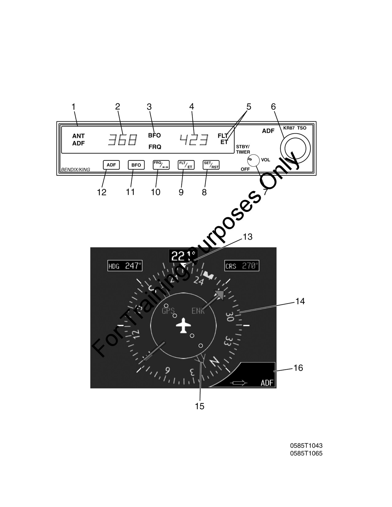
CESSNA
SECTION 9 - SUPPLEMENTS
MODEL 172S NAV III
SUPPLEMENT 7
BENDIX/KING KR87 AUTOMATIC DIRECTION
FINDER (ADF)
Figure S7-1
FAA APPROVED
172SPHAUS-S7-00
U.S.
S7-5