CESSNA 172S NAV III Skyhawk SP. Information Manual (2016) - page 5
SECTION 9 - SUPPLEMENTS
CESSNA
SUPPLEMENT 7
MODEL 172S NAV III
GENERAL (CONTINUED)
1.
ANT/ADF MODE ANNUNCIATOR - Antenna (ANT) is selected
when the ADF button is in the OUT position. This mode improves
the audio reception and is usually used for station identification.
The bearing pointer is deactivated and will park in the 90° relative
position. Automatic Direction Finder (ADF) mode is selected by
pushing the ADF button. This mode activates the bearing pointer
and will point in the direction of the station relative to the aircraft
heading.
2.
ACTIVE FREQUENCY DISPLAY - The frequency to which the
ADF is tuned is displayed here. The active ADF frequency can be
changed directly when either of the timer functions is selected.
3.
BFO (Beat Frequency Oscillator) ANNUNCIATOR - The BFO
mode is activated and annunciated by pushing the BFO button.
When BFO mode is active, the carrier wave and its morse code
identifier can be heard.
NOTE
CW signals (Morse Code) are unmodulated and no audio
will be heard without use of BFO. This type of signal is not
used in the United States air navigation. It is used in some
foreign countries and marine beacons.
4.
STANDBY FREQUENCY/FLIGHT TIME OR ELAPSED TIME
DISPLAY - When FRQ is shown, the STANDBY frequency is
shown in the right display. The STANDBY frequency is selected
using the frequency select knobs. The selected STANDBY
frequency is put into the active frequency window by pushing the
frequency transfer button. Either the standby frequency, the flight
timer, or the elapsed time is shown in this position. The flight
timer and elapsed timer replace the standby frequency which
goes into blind memory to be called back at any time by pushing
the FRQ button. Flight time or elapsed time are shown and
annunciated by depressing the FLT/ET button.
5.
FLIGHT TIMER AND ELAPSED TIMER MODE ANNUNCIATION
- Either the elapsed time
(ET) or flight time
(FLT) mode is
annunciated here.
(Continued Next Page)
FAA APPROVED
S7-6
U.S.
172SPHAUS-S7-00
CESSNA
SECTION 9 - SUPPLEMENTS
MODEL 172S NAV III
SUPPLEMENT 7
GENERAL (CONTINUED)
6. FREQUENCY SELECT KNOBS - Selects the standby frequency
when FRQ is displayed and directly selects the active frequency
whenever either of the time functions is selected. The frequency
selector knobs may be turned either clockwise or
counterclockwise. The small knob is pulled out to tune the 1's.
The small knob is pushed in to tune the 10's. The outer knob
tunes the 100's with rollover into the 1000's up to 1799. These
knobs are also used to set the desired time when the elapsed
timer is used in the countdown mode.
7. ON/OFF/VOLUME CONTROL SWITCH
(ON/OFF/VOL)
-
Controls power and audio output level. Turn the control switch
clockwise from the OFF position to energize the receiver and
increase audio volume. The KR87 has audio muting which
causes the audio output to be muted unless the receiver is locked
on a valid station.
8. SET/RESET ELAPSED TIMER BUTTON (SET/RST) - The SET/
RST button resets the elapsed timer whether it is being displayed
or not.
9. FLIGHT TIMER/ELAPSED TIMER MODE SELECTOR BUTTON
(FLT/ET) -- The FLT/ET button selects either Flight Timer mode or
Elapsed Timer mode when pushed.
10.FREQUENCY TRANSFER BUTTON (FRQ) - The FRQ transfer
button interchanges the active and standby frequencies when
pushed.
11.BFO (Beat Frequency Oscillator) BUTTON - The BFO button
selects the BFO mode when pushed in. (See note under item 3).
12.ADF BUTTON - The ADF button selects either the ANT mode or
the ADF mode. The ANT mode is selected when the ADF button
is in the out position. The ADF mode is selected when the ADF
button is pushed in.
13.LUBBER LINE - Indicates magnetic heading of the airplane.
14.ROTATING COMPASS ROSE (HSI COMPASS CARD) - The
rotating compass rose turns as the heading of the airplane
changes. The magnetic heading of the airplane is under the
lubber line.
15.BEARING POINTER - Shows magnetic bearing to the station.
16.BEARING INFORMATION WINDOW - Shows the type of pointer
that is being used as the ADF bearing pointer. If ADF is not
shown, push the BRG1 or BRG2 softkey until ADF is shown.
FAA APPROVED
172SPHAUS-S7-00
U.S.
S7-7
SECTION 9 - SUPPLEMENTS
CESSNA
SUPPLEMENT 7
MODEL 172S NAV III
OPERATING LIMITATIONS
Refer to Section
2 of the Pilot's Operating Handbook and FAA
Approved Flight Manual (POH/AFM).
EMERGENCY PROCEDURES
There is no change to the airplane emergency procedures when the
Bendix/King KR 87 Automatic Direction Finder (ADF) is installed.
NORMAL PROCEDURES
TO OPERATE AS AN AUTOMATIC DIRECTION FINDER:
1. OFF/VOL Control - ON
2. Frequency Selector Knobs - SELECT desired frequency in the
standby frequency display.
3. FRQ Button - PUSH to move the desired frequency from the
standby to the active position.
4. ADF Selector Switch (on audio control panel) - SELECT as
desired.
5. OFF/VOL Control - SET to desired volume level and identify that
desired station is being received.
6. PFD Softkey (on PFD)
- PUSH to show BRG1 and BRG2
softkeys.
7. BRG1 or BRG2 Softkey (on PFD) - PUSH to show ADF in
Bearing Information Window.
8. ADF Button - SELECT ADF mode and note magnetic bearing on
HSI.
(Continued Next Page)
FAA APPROVED
S7-8
U.S.
172SPHAUS-S7-00
CESSNA
SECTION 9 - SUPPLEMENTS
MODEL 172S NAV III
SUPPLEMENT 7
NORMAL PROCEDURES (CONTINUED)
ADF TEST (PREFLIGHT or IN FLIGHT):
1. ADF Button - SELECT ANT mode and note pointer moves to 90°
position.
2. ADF Button - SELECT ADF mode and note the pointer moves
without hesitation to the station bearing. Excessive pointer
sluggishness, wavering or reversals indicate a signal that is too
weak or a system malfunction.
TO OPERATE BFO:
1. OFF/VOL Control - ON
2. BFO Button - PRESS ON
3. ADF Selector Buttons (on audio control panel) - SET to desired
mode.
4. VOL Control - ADJUST to desired listening level.
NOTE
A 1000-Hz tone and Morse Code identifier is heard in the
audio output when a CW signal is received.
TO OPERATE FLIGHT TIMER:
1. OFF/VOL Control - ON
2. FLT/ET Mode Button - PRESS (once or twice) until FLT is
annunciated. Timer will already be counting since it is activated
by turning the unit on.
3. OFF/VOL Control - OFF and then ON if it is desired to reset the
flight timer.
TO OPERATE AS A COMMUNICATIONS RECEIVER ONLY:
1. OFF/VOL Control - ON
2. ADF Button - SELECT ANT mode
3. Frequency Selector Knobs - SELECT desired frequency in the
standby frequency display.
4. FRQ Button - PRESS to move the desired frequency from the
standby to the active position.
5. ADF Selector Buttons (on audio control panel) - SET to desired
mode.
6. VOL Control - ADJUST to desired listening level.
(Continued Next Page)
FAA APPROVED
172SPHAUS-S7-00
U.S.
S7-9
SECTION 9 - SUPPLEMENTS
CESSNA
SUPPLEMENT 7
MODEL 172S NAV III
NORMAL PROCEDURES (CONTINUED)
TO OPERATE ELAPSED TIME TIMER-COUNT UP MODE:
1. OFF/VOL Control - ON
2. FLT/ET Mode Button
- PRESS (once or twice) until ET is
annunciated.
3. SET/RST Button - PRESS momentarily to reset elapsed timer to
zero.
NOTE
The Standby Frequency which is in memory while Flight
Time or Elapsed Time modes are being displayed may be
called back by pushing the FRQ button, then transferred to
active by pushing the FRQ button again.
TO OPERATE ELAPSED TIME TIMER COUNT DOWN
MODE:
1.
OFF/VOL Control - ON
2.
FLT/ET Mode Button - PRESS (once or twice) until ET is
annunciated.
3.
SET/RST Button - PRESS until the ET annunciation begins to
flash.
4.
FREQUENCY SELECTOR KNOBS - SET desired time in the
elapsed time display. The small knob is pulled out to tune the 1's.
The small knob is pushed in to tune the 10's. The outer knob
tunes minutes up to 59 minutes.
NOTE
Selector knobs remain in the time set mode for 15 seconds
after the last entry or until the SET/RST, FLT/ET or FRQ
button is pressed.
5.
SET/RST Button - PRESS to start countdown. When the timer
reaches 0, it will start to count up as display flashes for 15
seconds.
NOTE
While FLT or ET are displayed, the active frequency on the
left side of the window may be changed, by using the
frequency selector knobs, without any effect on the stored
standby frequency or the other modes.
(Continued Next Page)
FAA APPROVED
S7-10
U.S.
172SPHAUS-S7-00
CESSNA
SECTION 9 - SUPPLEMENTS
MODEL 172S NAV III
SUPPLEMENT 7
NORMAL PROCEDURES (CONTINUED)
ADF OPERATION NOTES:
ERRONEOUS ADF BEARING DUE TO RADIO FREQUENCY
PHENOMENA:
In the U.S., the FCC, which assigns AM radio frequencies, occasionally
will assign the same frequency to more than one station in an area.
Certain conditions, such as Night Effect, may cause signals from such
stations to overlap. This should be taken into consideration when using
AM broadcast stations for navigation.
Sunspots and atmospheric phenomena may occasionally distort
reception so that signals from two stations on the same frequency will
overlap. For this reason, it is always wise to make positive identification
of the station being tuned, by switching the function selector to ANT
and listening for station call letters.
ELECTRICAL STORMS:
In the vicinity of electrical storms, an ADF indicator pointer tends to
swing from the station tuned toward the center of the storm.
NIGHT EFFECT:
This is a disturbance particularly strong just after sunset and just after
dawn. An ADF indicator pointer may swing erratically at these times. If
possible, tune to the most powerful station at the lowest frequency. If
this is not possible, take the average of pointer oscillations to determine
station bearing.
MOUNTAIN EFFECT:
Radio waves reflecting from the surface of mountains may cause the
pointer to fluctuate or show an erroneous bearing. This should be taken
into account when taking bearings over mountainous terrain.
COASTAL REFRACTION:
Radio waves may be refracted when passing from land to sea or when
moving parallel to the coastline. This also should be taken into account.
FAA APPROVED
172SPHAUS-S7-00
U.S.
S7-11
SECTION 9 - SUPPLEMENTS
CESSNA
SUPPLEMENT 7
MODEL 172S NAV III
PERFORMANCE
There is no change in airplane performance when the Bendix/King KR
87 Automatic Direction Finder
(ADF) is installed. However, the
installation of an externally mounted antenna or related external
antennas, will result in a minor reduction in cruise performance.
FAA APPROVED
S7-12
U.S.
172SPHAUS-S7-00

Pilot’s Operating Handbook and
FAA Approved Airplane Flight Manual
CESSNA MODEL 172S
NAV III AVIONICS OPTION
Serials 172S9810 and On
SUPPLEMENT 8
RUSSIAN FEDERATION (RF) AND OTHER
COMMONWEALTH OF INDEPENDENT
STATES (CIS) COUNTRIES
SERIAL NO.
REGISTRATION NO.
This supplement must be inserted into Section 9 of the Pilot's Operating Handbook
and FAA Approved Airplane Flight Manual when the airplane is operated within the
territory of the Russian Federation (RF) and other Commonwealth of Independent
States (CIS) Countries. This supplement is approved by the U.S. Federal Aviation
Administration (FAA) on behalf of the Russian Aviation Register.
4 APRIL 2006
COPYRIGHT © 2006
CESSNA AIRCRAFT COMPANY
WICHITA, KANSAS, USA
172SPHAUS-S8-00
U.S.
S8-1
SECTION 9 - SUPPLEMENTS
CESSNA
SUPPLEMENT 8
MODEL 172S NAV III
SUPPLEMENT 8
RUSSIAN FEDERATION
(RF) AND OTHER
COMMONWEALTH OF INDEPENDENT STATES
(CIS) COUNTRIES
Use the Log of Effective Pages to determine the current status of this
supplement.
Pages affected by the current revision are indicated by an asterisk (*)
preceding the page number.
Supplement Status Date
Original Issue
4 April 2006
LOG OF EFFECTIVE PAGES
Page
Page
Revision
Number
Status
Number
S8-1 thru S8-21/S8-22
Original
0
Approved for RF and CIS Countries Only
FAA APPROVED
S8-2
U.S.
172SPHAUS-S8-00
CESSNA
SECTION 9 - SUPPLEMENTS
MODEL 172S NAV III
SUPPLEMENT 8
SERVICE BULLETIN CONFIGURATION LIST
The following is a list of Service Bulletins that are applicable to the
operation of the airplane, and have been incorporated into this
supplement. This list contains only those Service Bulletins that are
currently active.
Airplane Serial
Revision
Incorporated
Number
Title
Effectivity
Incorporated
in Airplane
Approved for RF and CIS Countries Only
FAA APPROVED
172SPHAUS-S8-00
U.S.
S8-3
SECTION 9 - SUPPLEMENTS
CESSNA
SUPPLEMENT 8
MODEL 172S NAV III
RUSSIAN FEDERATION
(RF) AND OTHER
COMMONWEALTH OF INDEPENDENT STATES
(CIS) COUNTRIES
GENERAL
This supplement must be placed in Section 9 of the basic Pilot’s
Operating Handbook and FAA Approved Airplane Flight Manual, when
the airplane is operated within the territory of the Russian Federation
(RF) and other Commonwealth of Independent States (CIS) Countries.
The information contained herein supplements the information of the
basic Pilot’s Operating Handbook and FAA Approved Airplane Flight
Manual. Limitations, procedures, and performance found in this
supplement supersedes those found in the basic Pilot’s Operating
Handbook and FAA Approved Airplane Flight Manual. For limitations,
procedures, and performance information not contained in this
supplement, consult the basic Pilot’s Operating Handbook and FAA
Approved Airplane Flight Manual.
NOTE
In RF and CIS countries, FAA operating rules (i.e., 14 CFR
Part 91 and 14 CFR Part 135) are not applicable. The
airplane must be equipped and operated in accordance
with RF and CIS applicable operational requirements.
Approved for RF and CIS Countries Only
FAA APPROVED
S8-4
U.S.
172SPHAUS-S8-00
CESSNA
SECTION 9 - SUPPLEMENTS
MODEL 172S NAV III
SUPPLEMENT 8
OPERATING LIMITATIONS
The following Limitations supersede and/or are in addition to the
Limitations set forth in the basic Pilot’s Operating Handbook and FAA
Approved Airplane Flight Manual:
Maximum number of airplane occupants: 1 Pilot plus 3 Passengers
Maximum bank angle: 60°
Operation in heavy precipitation (rain or snow) is prohibited.
Flight into known significant convective activity and thunderstorms is
prohibited.
Flight into known icing or freezing rain is prohibited.
Operations in RF and CIS airspace are approved only on routes
covered by ATC ground facilities using RBS mode.
The Nav III Avionics Option is approved for Category I ILS approach
operations only.
The Global Positioning Satellite (GPS) system is not approved for
approach.
Operation over water beyond the Maximum Glide distance from shore
is prohibited (Refer to the POH/AFM, Section 3, Figure 3-1).
Spins are prohibited at weight more than 2100 pounds.
Autopilot must be installed and operational for all operations within RF
and CIS airspace.
Approved for RF and CIS Countries Only
FAA APPROVED
172SPHAUS-S8-00
U.S.
S8-5
SECTION 9 - SUPPLEMENTS
CESSNA
SUPPLEMENT 8
MODEL 172S NAV III
KINDS OF OPERATION LIMITS
The following Kinds of Operations Equipment List (KOEL) identifies the
equipment required to be operational for airplane airworthiness in the
listed kind of operations for airplanes operating within the territory of the
Russian Federation and other Commonwealth of Independent States
countries.
The following KOEL supersedes the KOEL located in Section 2 of the
POH/AFM.
KINDS OF OPERATIONS EQUIPMENT LIST
KIND OF OPERATION
V
I
V
F
I
F
F
R
F
R
R
R
N
N
D
I
D
I
A
G
A
G
Y
H
Y
H
System, Instrument, Equipment
and/or Function
T
T
COMMENTS
PLACARDS AND MARKINGS
172S Nav III POH/AFM
1
1
1
1
Accessible to pilot
in flight
1
1
1
1
Accessible to pilot
Garmin G1000TM Cockpit
in flight
Reference Guide
AIR CONDITIONING
1 - Forward Avionics Fan
1
1
1
1
2 - PFD Fan
0
0
0
0
3 - MFD Fan
0
0
0
0
4 - Aft Avionics Fan
1
1
1
1
AUTOFLIGHT
1 - Bendix/King KAP 140 POH
1
1
1
1
Accessible to pilot
Supplement
in flight when using
autopilot
2 - Bendix/King KAP 140
1
1
1
1
Autopilot
(Continued Next Page)
Approved for RF and CIS Countries Only
FAA APPROVED
S8-6
U.S.
172SPHAUS-S8-00

CESSNA
SECTION 9 - SUPPLEMENTS
MODEL 172S NAV III
SUPPLEMENT 8
KINDS OF OPERATIONS EQUIPMENT LIST (Continued)
KIND OF OPERATION
V
I
V
F
I
F
F
R
F
R
R
R
N
N
D
I
D
I
A
G
A
G
Y
H
Y
H
System, Instrument, Equipment
and/or Function
T
T
COMMENTS
COMMUNICATIONS
1 - VHF COM
1
1
1
1
ELECTRICAL POWER
1 - 24V Main Battery
1
1
1
1
2 - 28V Alternator
1
1
1
1
3 - 24V Standby Battery
1
1
1
1
* Refer to Note 1
4 - Main Ammeter
1
1
1
1
5 - Standby Ammeter
1
1
1
1
* Refer to Note 1
EQUIPMENT AND
FURNISHINGS
1 - Seat Belt Assembly
1
1
1
1
Each Seat
Occupant
2 - Shoulder Harness
1
1
1
1
Front Seat
Occupants
NOTE
1. The European Aviation Safety
Agency (EASA) requires the
24V Standby Battery and Standby Ammeter to successfully
complete the pre-flight check before operating the airplane in
VFR night, IFR day, or IFR night conditions in Europe. Correct
operation of the 24V Standby Battery and Standby Ammeter is
recommended for all other operations.
(Continued Next Page)
Approved for RF and CIS Countries Only
FAA APPROVED
172SPHAUS-S8-00
U.S.
S8-7
SECTION 9 - SUPPLEMENTS
CESSNA
SUPPLEMENT 8
MODEL 172S NAV III
KINDS OF OPERATIONS EQUIPMENT LIST (Continued)
KIND OF OPERATION
V
I
V
F
I
F
F
R
F
R
R
R
N
N
D
I
D
I
A
G
A
G
Y
H
Y
H
System, Instrument, Equipment
and/or Function
T
T
COMMENTS
FLIGHT CONTROLS
1 - Flap Position Indicator
1
1
1
1
2 - Flap Motor
1
1
1
1
3 - Elevator Trim System
1
1
1
1
4 - Elevator Trim Indicator
1
1
1
1
FUEL SYSTEM
1 - Electric Fuel Pump
1
1
1
1
2 - Fuel Quantity Indicator - LH
1
1
1
1
Tank
3 - Fuel Quantity Indicator - RH
1
1
1
1
Tank
ICE AND RAIN PROTECTION
1 - Alternate Static Air Source
0
1
1
1
2 - Alternate Induction Air
0
1
1
1
System
INDICATING/RECORDING
SYSTEM
1 - Stall Warning System
1
1
1
1
2 - System Annunciator and
1
1
1
1
Warning Displays
LANDING GEAR
1 - Wheel Fairings
0
0
0
0
Removable
(Continued Next Page)
Approved for RF and CIS Countries Only
FAA APPROVED
S8-8
U.S.
172SPHAUS-S8-00
CESSNA
SECTION 9 - SUPPLEMENTS
MODEL 172S NAV III
SUPPLEMENT 8
KINDS OF OPERATIONS EQUIPMENT LIST (Continued)
KIND OF OPERATION
V
I
V
F
I
F
F
R
F
R
R
R
N
N
D
I
D
I
A
G
A
G
Y
H
Y
H
System, Instrument, Equipment
and/or Function
T
T
COMMENTS
LIGHTING
1 - PFD Bezel Lighting
0
0
0
1
2 - PFD Backlighting
1
1
1
*Refer to Note 2
3 - MFD Bezel Lighting
0
0
0
1
4 - MFD Backlighting
1
1
1
*Refer to Note 3
5 - Switch and Circuit Breaker
0
1
0
1
Panel Lighting
6 - Airspeed Indicator (Standby)
0
1
0
1
Internal Lighting
7 - Altimeter (Standby) Internal
0
1
0
1
Lighting
8 - Non-stabilized Magnetic
0
1
0
1
Compass Internal Lighting
9 - Attitude Indicator (Vacuum)
0
1
0
1
Internal Lighting
10 - Cockpit Flood Light
0
1
0
1
11 - Aircraft Position (NAV) Lights
0
1
1
1
NOTE
2. PDF backlighting is
required
for
day VFR flight if MFD
backlighting has failed. Display backup mode must be active
so engine indicators are shown.
3. MFD backlighting is required for day VFR flight if PDF
backlighting has failed. Display backup mode must be active
so flight instruments are shown.
(Continued Next Page)
Approved for RF and CIS Countries Only
FAA APPROVED
172SPHAUS-S8-00
U.S.
S8-9

SECTION 9 - SUPPLEMENTS
CESSNA
SUPPLEMENT 8
MODEL 172S NAV III
KINDS OF OPERATIONS EQUIPMENT LIST (Continued)
KIND OF OPERATION
V
I
V
F
I
F
F
R
F
R
R
R
N
N
D
I
D
I
A
G
A
G
Y
H
Y
H
System, Instrument, Equipment
and/or Function
T
T
COMMENTS
LIGHTING (Continued)
12 - STROBE Light System
1
1
1
1
13 - BEACON Light
0
0
0
0
14 - TAXI Light
0
0
0
0
15 - LAND (Landing) Light
0
1
0
1
Operations for hire
only
NAVIGATION AND PITOT-
STATIC SYSTEM
1 - G1000 Airspeed Indicator
1
1
1
1
2 - Standby Airspeed Indicator
1
1
1
1
3 - G1000 Altimeter
1
1
1
1
4 - Standby Altimeter
1
1
1
1
5 - G1000 Vertical Speed
1
1
1
1
Indicator
6 - G1000 Attitude Indicator
1
1
1
1
7 - Attitude Indicator - Vacuum
1
1
1
1
(Standby)
8 - G1000 Directional Indicator
1
1
1
1
(HSI)
9 - G1000 Turn Coordinator
1
1
1
1
10 - Non-stabilized Magnetic
1
1
1
1
Compass
11 - VHF Navigation Radio
A/R
A/R
A/R
A/R
As Required Per
(VOR/LOC/GS)
Procedure
(Continued Next Page)
Approved for RF and CIS Countries Only
FAA APPROVED
S8-10
U.S.
172SPHAUS-S8-00

CESSNA
SECTION 9 - SUPPLEMENTS
MODEL 172S NAV III
SUPPLEMENT 8
KINDS OF OPERATIONS EQUIPMENT LIST (Continued)
KIND OF OPERATION
V
I
V
F
I
F
F
R
F
R
R
R
N
N
D
I
D
I
A
G
A
G
Y
H
Y
H
System, Instrument, Equipment
and/or Function
T
T
COMMENTS
NAVIGATION AND PITOT-
STATIC SYSTEM (Continued)
12 - GPS Receiver/Navigator
A/R
A/R
A/R
A/R
As Required Per
Procedure
13 - ADF Navigation Radio
A/R
A/R
A/R
A/R
As Required Per
Procedure
14 - Marker Beacon Receiver
A/R
A/R
A/R
A/R
As Required Per
Procedure
15 - Blind Altitude Encoder
A/R
1
1
1
As Required Per
Procedure
16 - Clock
1
1
1
1
VACUUM
1 - Engine-driven Vacuum Pump
1
1
1
1
2 - Vacuum Indicator
1
1
1
1
ENGINE FUEL AND CONTROL
1 - Fuel Flow Indicator
1
1
1
1
ENGINE INDICATING
1 - Tachometer (RPM)
1
1
1
1
2 - Cylinder Head Temperature
0
0
0
0
(CHT) Indicator
3 - Oil Pressure Indicator
1
1
1
1
4 - Oil Temperature Indicator
1
1
1
1
ENGINE OIL
1 - Engine Crankcase Dipstick
1
1
1
1
Approved for RF and CIS Countries Only
FAA APPROVED
172SPHAUS-S8-00
U.S.
S8-11
SECTION 9 - SUPPLEMENTS
CESSNA
SUPPLEMENT 8
MODEL 172S NAV III
FUEL LIMIATIONS
Approved Fuels:100LL (ASTM-D910)
100 (Formerly 100/130) (ASTM-D910)
B91/115 (GOST 1012-72)
See the latest revision of Lycoming Service Instruction No.1070 for
approved fuel grades.
Fuels must contain an anti-icing fuel additive (Isopropyl Alcohol or
DiEGME) in concentrations mixed as noted in Section 8 of the POH/
AFM.
MAXIMUM OPERATING ALTITUDE LIMIT
MAXIMUM APPROVED OPERATING ALTITUDE: 3000 meters (9800
Feet).
If oxygen is provided for each occupant, the airplane can be operated
up to the maximum altitude for the oxygen system, or 4200 meters
(13,779 feet), whichever altitude is lower.
OUTSIDE AIR TEMPERATURE LIMITS
Ground operations limits for a cold day:
Minus 40°C
Ground operations limits for a hot day:
40°C
Approved for RF and CIS Countries Only
FAA APPROVED
S8-12
U.S.
172SPHAUS-S8-00
CESSNA
SECTION 9 - SUPPLEMENTS
MODEL 172S NAV III
SUPPLEMENT 8
TAXI OPERATIONAL LIMITS
Uncontaminated paved taxiway:
• Maximum wind velocity while taxiing:
14 m/s (27 Knots)
Paved taxiway contaminated with precipitation:
• Maximum wind velocity while taxiing:
3 m/s (5 Knots)
Refer to Section 4 of the POH/AFM for additional information on taxiing.
TAKEOFF AND LANDING OPERATIONAL LIMITS
Maximum Takeoff and Landing Altitude:
2438 meters (8000 Feet)
Maximum Headwind Velocity:
14 m/s (27 Knots)
Maximum Tailwind Velocity:
5 m/s (10 Knots)
Maximum crosswind velocity on
uncontaminated paved runway:
7m/s (15 Knots)
ALLOWABLE RUNWAY SURFACE CONDITIONS
1. Uncontaminated runway with paved surface.
2. Paved runway contaminated with precipitation (average depth
and types):
a. Water, less that 10.0 mm.
b. Slush, less than 10.0 mm.
c. Loose snow less than 30.0 mm.
3. Unpaved runway
a. Surface hardness must be greater than 7 kg/cm2.
NOTE
Landing on contaminated unpaved runways is prohibited.
Operating with the landing gear fairings removed is recommended on
wet or unpaved runways when temperatures are near or below
freezing.
Approved for RF and CIS Countries Only
FAA APPROVED
172SPHAUS-S8-00
U.S.
S8-13
SECTION 9 - SUPPLEMENTS
CESSNA
SUPPLEMENT 8
MODEL 172S NAV III
MAXIMUM CROSSWIND ON CONTAMINATED RUNWAYS
Contaminated paved runways with:
Water, less than 10.0 mm
3 m/s (5 Knots)
Slush, less than 10.0 mm
3 m/s (5 Knots)
Loose snow, less than 30.0 mm
3 m/s (5 Knots)
Paved runway with less than 3 mm of water, snow or slush and braking
coefficient of friction(µ) of:
µ=0.3 (poor braking)
3 m/s (5 Knots)
µ=0.4 (average braking)
5 m/s (9 Knots)
µ=0.5 (good braking, dry or
equivalent to dry runway)
7 m/s (15 Knots)
REQUIRED PLACARDS AND MARKINGS
Above exit doors, in clear view of each occupant:
EMERGENCY PROCEDURES
The following pages from Section 3 of the POH/AFM have instructions
for operations in RF and CIS countries. These pages replace the
procedures found in Section 3 of the POH/AFM for those operations:
(Continued Next Page)
Approved for RF and CIS Countries Only
FAA APPROVED
S8-14
U.S.
172SPHAUS-S8-00
CESSNA
SECTION 9 - SUPPLEMENTS
MODEL 172S NAV III
SUPPLEMENT 8
EMERGENCY PROCEDURES (Continued)
FORCED LANDINGS
EMERGENCY LANDING WITHOUT ENGINE POWER
1. Passenger Seats - MOST UPRIGHT POSITION
2. Seats and Seat Belts - SECURE
3. Airspeed - 70 KIAS Flaps UP
65 KIAS Flaps 10° - FULL
4. Mixture Control - IDLE CUT OFF
5. FUEL SHUTOFF Valve - OFF (pull full out)
6. MAGNETOS Switch - OFF
7. Wing Flaps - AS REQUIRED (FULL recommended)
8. STBY BATT Switch - OFF
9. MASTER Switch (ALT and BAT) - OFF (when landing is assured)
10.Doors - UNLATCH PRIOR TO TOUCHDOWN
11.Touchdown - SLIGHTLY TAIL LOW
12.Brakes - APPLY HEAVILY
13.Emergency Radio
- Operate
(P-855A1) Russian made
Emergency Radio according to attached instructions.
PRECAUTIONARY LANDING WITH ENGINE POWER
1. Passenger Seats - MOST UPRIGHT POSITION
2. Seats and Seat Belts - SECURE
3. Airspeed - 65 KIAS
4. Wing Flaps - 20°
5. Selected Field - FLY OVER, noting terrain and obstructions.
6. Wing Flaps - FULL (on final approach)
7. Airspeed - 65 KIAS
8. STBY BATT Switch - OFF
9. MASTER Switch (ALT and BAT) - OFF
10.Doors - UNLATCH PRIOR TO TOUCHDOWN
11.Touchdown - SLIGHTLY TAIL LOW
12.Mixture Control - IDLE CUT OFF
13.MAGNETOS Switch - OFF
14.Brakes - APPLY HEAVILY
15.Emergency Radio
- Operate
(P-855A1) Russian made
Emergency Radio according to attached instructions.
(Continued Next Page)
Approved for RF and CIS Countries Only
FAA APPROVED
172SPHAUS-S8-00
U.S.
S8-15
SECTION 9 - SUPPLEMENTS
CESSNA
SUPPLEMENT 8
MODEL 172S NAV III
EMERGENCY PROCEDURES (Continued)
DITCHING
1. Radio - TRANSMIT MAYDAY on 121.5 MHz, giving location and
intentions and SQUAWK 7700.
2. Heavy Objects (in baggage area) - SECURE OR JETTISON (if
possible)
3. Passenger Seats - MOST UPRIGHT POSITION
4. Seats and Seat Belts - SECURE
5. Wing Flaps - 20° to FULL
6. Power - ESTABLISH 300 FT/MIN DESCENT AT 55 KIAS
NOTE
If no power is available, approach at 65 KIAS with Flaps UP
or 60 KIAS with Flaps 10°.
7. Approach - High Winds, Heavy Seas - INTO THE WIND
Light Winds, Heavy Swells - PARALLEL TO SWELLS
8. Cabin Doors - UNLATCH
9. Touchdown - LEVEL ATTITUDE AT ESTABLISHED RATE-OF-
DESCENT.
10.Face - CUSHION at touchdown with folded coat.
11.ELT - ACTIVATE
12.Airplane - EVACUATE through cabin doors. If necessary, open
window and flood cabin to equalize pressure so doors can be
opened.
13.Life Vests and Raft - INFLATE WHEN CLEAR OF AIRPLANE.
14.Emergency Radio
- Operate
(P-855A1) Russian made
Emergency Radio according to attached instructions.
(Continued Next Page)
Approved for RF and CIS Countries Only
FAA APPROVED
S8-16
U.S.
172SPHAUS-S8-00
CESSNA
SECTION 9 - SUPPLEMENTS
MODEL 172S NAV III
SUPPLEMENT 8
EMERGENCY PROCEDURES (Continued)
FORCED LANDINGS
If all attempts to restart the engine fail and a forced landing is imminent,
select a suitable field and prepare for the landing as discussed under
the Emergency Landing Without Engine Power checklist. Transmit
Mayday message on 121.5 MHz giving location and intentions and
squawk 7700.
Before attempting an "off-airport" landing with engine power available,
one should fly over the landing area at a safe, but low altitude, to
inspect the terrain for obstructions and surface conditions, proceeding
as discussed in the Precautionary Landing With Engine Power
checklist.
Prepare for ditching by securing or jettisoning heavy objects located in
the baggage area and collect folded coats for protection of occupants'
face at touchdown. Transmit Mayday messages on 121.5 MHz giving
location and intentions and squawk
7700. Avoid a landing flare
because of the difficulty in judging height over a water surface. The
checklist assumes the availability of power to make a precautionary
water landing. If power is not available, use of the airspeeds noted with
minimum flap extension will provide a more favorable attitude for a
power off ditching.
In a forced landing situation, do not turn off the AVIONICS switch or
MASTER switch until a landing is assured. Premature deactivation of
the switches will disable all airplane electrical systems.
Following evacuation from the airplane, operate (P-885A1) Russian
made Emergency Radio according to the attached instructions
provided with the radio.
Approved for RF and CIS Countries Only
FAA APPROVED
172SPHAUS-S8-00
U.S.
S8-17
SECTION 9 - SUPPLEMENTS
CESSNA
SUPPLEMENT 8
MODEL 172S NAV III
NORMAL PROCEDURES
NOTE
• In a left slip maneuver, the airspeed indicator may show
a maximum of 20 knots below the actual airspeed. In a
right slip maneuver, the airspeed indicator may show a
maximum of 5 knots above the actual airspeed. This is
because of the single static pressure port on the 172S
left forward fuselage.
• At airspeeds greater than 120 KIAS, close the throttle if
necessary to keep engine speed below 2700 RPM.
In the event of GPS failure when operating along routes that are + 5 km
wide without VOR/DME facilities and no NDB coverage, airplane
position between the width of such routes can only be assured up to
approximately 140 km from the last known position.
The pilot is to disregard Supplement 1 of the POH/AFM describing the
pointer Model 3000-11 or 4000-11 Emergency Locator Transmitter
(ELT).
COLD WEATHER OPERATIONS
NOTE
• The Garmin GDU 1040 PFD/MFD requires a warm-up
time of up to 30 minutes when exposed to Minus 40°C
for an extended period. A warm-up time of up to 15
minutes may be required when exposed to Minus 30°C
for an extended period of time.
• During operation at outside temperatures below ISA
Standard, the engine may develop greater than rated
power at normal rated RPM, particularly at lower
altitudes.
Approved for RF and CIS Countries Only
FAA APPROVED
S8-18
U.S.
172SPHAUS-S8-00
CESSNA
SECTION 9 - SUPPLEMENTS
MODEL 172S NAV III
SUPPLEMENT 8
COLD SOAK
If extended exposure to cold weather is expected, refer to Maintenance
Manual procedures to prepare the airplane for cold soak. If the airplane
has cold soaked for more than two hours at temperatures colder than
Minus 10°C, refer to Maintenance Manual procedures to prepare the
airplane for flight. Cold temperatures will affect control cable tension.
See Chapter 27 of the Maintenance Manual for flight control cable
tensions. See Chapter 12 of the Maintenance Manual for information
on lubrication and greasing of moving parts. See Section 8 of the POH/
AFM for correct engine oil viscosity. See paragraphs on Cold Weather
Operation in Section 4 of the POH/AFM for additional information on
procedures for operating the airplane in cold temperatures.
When the outside temperature is less than Minus 34ºC, the airplane
batteries should be removed and stored in the warm conditions.
The engine must be preheated before starting if engine temperature is
less than Minus 6°C.
When the outside temperature is less than
0°C, moisture from
combustion can freeze on the engine spark plugs if the engine does not
continue to operate after it is started. This will prevent the engine from
starting again. Preheat the engine to more than 0°C before starting the
engine again.
Preheat the engine by directing warm air into the engine cooling inlets
behind the propeller. The temperature of the preheating air should not
be more than 120°C to prevent damage to the exterior paint. Open
flames are prohibited near the airplane.
Before takeoff, preheat the airplane cabin to more than Minus 30°C for
correct operation of the standby altimeter. If there is no warning that an
instrument is operating incorrectly, all other instruments will operate
down to the minimum temperature of the airplane.
Before operating the airplane, it is recommended to heat the cabin to a
comfortable temperature for the cabin occupants.
Approved for RF and CIS Countries Only
FAA APPROVED
172SPHAUS-S8-00
U.S.
S8-19
SECTION 9 - SUPPLEMENTS
CESSNA
SUPPLEMENT 8
MODEL 172S NAV III
PERFORMANCE
OPERATION ON CONTAMINATED RUNWAY
The takeoff distance on a paved runway with no more than 3 mm of
precipitation is equal to dry runway takeoff distance.
The takeoff distance on a paved runway with precipitation greater than
3 mm is 20% greater than the dry runway takeoff distance.
To determine the required landing distance on a contaminated paved
runway, the dry runway landing distance shall be multiplied by the
following K factors:
Conditions
Basic Airfield
Alternate Airfield
µ > 0.5
K = 1.67
K = 1.43
(good braking and runway with no
standing water)
0.5 > µ > 0.4
K = 1.72
K = 1.72
(Average Braking)
More than 3 mm precipitation
K = 2.00
K = 2.00
or
0.4 > µ > 0.3
(Poor Braking)
For unpaved runway landing distance, refer to figure 5-12 in the POH/
AFM for the correction applied to grass runway landing distance.
Approved for RF and CIS Countries Only
FAA APPROVED
S8-20
U.S.
172SPHAUS-S8-00

CESSNA
SECTION 9 - SUPPLEMENTS
MODEL 172S NAV III
SUPPLEMENT 8
LANDING DISTANCE CORRECTION FACTORS
FOR CONTAMINATED PAVED RUNWAYS
Figure S8-1
Approved for RF and CIS Countries Only
FAA APPROVED
172SPHAUS-S8-00
U.S.
S8-21/S8-22

CESSNA MODEL 172S
NAV III AVIONICS OPTION
Serials 172S9810 and On
SUPPLEMENT 9
ARTEX ME406
EMERGENCY LOCATOR TRANSMITTER (ELT)
SERIAL NO.
REGISTRATION NO.
This supplement must be inserted into Section 9 of the Pilot's Operating Handbook
and FAA Approved Airplane Flight Manual when the Artex ME406 Emergency
Locator Transmitter (ELT) is installed.
30 OCTOBER 2006
COPYRIGHT © 2006
CESSNA AIRCRAFT COMPANY
WICHITA, KANSAS, USA
172SPHAUS-S9-00
U.S.
S9-1
SECTION 9 - SUPPLEMENTS
CESSNA
SUPPLEMENT 9
MODEL 172S NAV III
SUPPLEMENT 9
ARTEX ME406 EMERGENCY LOCATOR TRANSMITTER
(ELT)
Use the Log of Effective Pages to determine the current status of this
supplement.
Pages affected by the current revision are indicated by an asterisk (*)
preceding the page number.
Supplement Status
Date
Original Issue
30 October 2006
LOG OF EFFECTIVE PAGES
Page
Page
Revision
Number
Status
Number
S9-1 thru S9-8
Original
0
FAA APPROVED
S9-2
U.S.
172SPHAUS-S9-00
CESSNA
SECTION 9 - SUPPLEMENTS
MODEL 172S NAV III
SUPPLEMENT 9
SERVICE BULLETIN CONFIGURATION LIST
The following is a list of Service Bulletins that are applicable to the
operation of the airplane, and have been incorporated into this
supplement. This list contains only those Service Bulletins that are
currently active.
Airplane Serial
Revision
Incorporated
Number Title
Effectivity
Incorporated
in Airplane
FAA APPROVED
172SPHAUS-S9-00
U.S.
S9-3
SECTION 9 - SUPPLEMENTS
CESSNA
SUPPLEMENT 9
MODEL 172S NAV III
ARTEX ME406 EMERGENCY LOCATOR
TRANSMITTER (ELT)
GENERAL
The Artex ME406 Emergency Locator Transmitter (ELT) installation
uses a solid-state
2-frequency transmitter powered by an internal
lithium battery. The ME406 is also equipped with an instrument panel-
mounted remote switch assembly, that includes a red warning light, and
an external antenna mounted on the top of the tailcone. The remote
switch assembly is installed along the upper right instrument panel and
controls ELT operating modes from the flight crew station. When the
remote switch is set to the ARM position, the transmitter is energized
only when the internal "G” switch senses longitudinal inertia forces per
TSO-C91a/TSO-C126. When the remote switch is set to the ON
position, the transmitter is immediately energized.
The ME406 transmitter unit is located in the tailcone along the right
side behind the baggage compartment aft panel. On the ELT
transmitter unit is a panel containing an ARM/ON switch and a
transmitter warning light.
The ELT installation uses two different warnings to tell the pilot when
the ELT is energized. The aural warning is an unusual sound that is
easily heard by the pilot. The visual warning is a flashing red light
directly above the remote switch that shows the pilot that the ELT has
been activated.
When the ME406 is energized, the ELT transmits the standard swept
tone signal on the international VHF frequency of 121.5 MHz until
battery power is gone. The 121.5 MHz signal is mainly used to pinpoint
the beacon during search and rescue operations, and is monitored by
general aviation, commercial aircraft, and government agencies.
In addition, for the first 24 hours of the ELT being energized, a 406.028
MHz signal is transmitted at 50 second intervals. This transmission
lasts 440 milliseconds and contains identification data programmed into
the ELT and is received by COSPAS/SARSAT satellites. The
transmitted data may include the Aircraft ID, ELT Serial Number,
Country Code, and COSPAS/SARSAT ID.
(Continued Next Page)
FAA APPROVED
S9-4
U.S.
172SPHAUS-S9-00

CESSNA
SECTION 9 - SUPPLEMENTS
MODEL 172S NAV III
SUPPLEMENT 9
ARTEX ME406 ELT CONTROL PANEL
1.
ELT PANEL SWITCH (2-Position Toggle Switch):
a. ARM
(OFF)
- Turns OFF and ARMS transmitter for
automatic activation if “G” switch senses a predetermined
deceleration level.
b. ON
- Activates transmitter instantly. The ON position
bypasses the automatic activation switch. The RED
warning light on ELT panel and on the remote switch
assembly mounted on the instrument panel should come
on.
2.
TRANSMITTER WARNING LIGHT - Light comes on RED to
indicate the transmitter is transmitting a distress signal.
3.
ANTENNA RECEPTACLE - Connects to the antenna mounted
on top of tailcone.
4.
REMOTE CABLE JACK - Connects to the ELT remote switch
assembly located on the upper right instrument panel.
5.
REMOTE SWITCH ASSEMBLY - (2-Position Rocker Switch):
a. ARM
(OFF)
- Turns OFF and ARMS transmitter for
automatic activation if “G” switch senses a predetermined
deceleration level.
b. ON
- Remotely activates the transmitter for test or
emergency situations. The RED warning light above the
rocker switch comes on to indicate that the transmitter is
transmitting a distress signal.
Figure S9-1
FAA APPROVED
172SPHAUS-S9-00
U.S.
S9-5
SECTION 9 - SUPPLEMENTS
CESSNA
SUPPLEMENT 9
MODEL 172S NAV III
OPERATING LIMITATIONS
There are no additional airplane operating limitations when the Artex
ME406 ELT is installed.
The airplane owner or operator must register the ME406 ELT with the
applicable civil aviation authority before use to make sure that the
identification code transmitted by the ELT is in the COSPAS/SARSAT
database. Refer to www.cospas-sarsat.org for registration information.
Refer to 14 CFR 91.207 for ELT inspection requirements. The ME406
must be inspected and tested by an approved technician using the
correct test equipment under the appropriate civil aviation authorities
approved conditions.
FAA APPROVED
S9-6
U.S.
172SPHAUS-S9-00
CESSNA
SECTION 9 - SUPPLEMENTS
MODEL 172S NAV III
SUPPLEMENT 9
EMERGENCY PROCEDURES
If a forced landing is necessary, set the remote switch to the ON
position before landing. This is very important in remote or
mountainous terrain. The red warning light above the remote switch will
flash and the aural warning will be heard.
After a landing when search and rescue aid is needed, use the ELT as
follows:
NOTE
The ELT remote switch assembly could be inoperative if
damaged during a forced landing. If inoperative, the inertia
“G” switch will activate automatically. However, to turn the
ELT OFF and ON again requires manual switching of the
ELT panel switch which is located on the ELT unit.
1.
MAKE SURE THE ELT IS ENERGIZED:
a. If the red warning light above the remote switch is not
flashing, set the remote switch to the ON position.
b. Listen for the aural warning. If the COM radio(s) operate and
can be energized safely (no threat of fire or explosion),
energize a COM radio and set the frequency to 121.5 MHz.
The ELT tone should be heard on the COM radio if the ELT
is working correctly. When done, de-energize the COM
radio(s) to conserve the airplane battery power.
c. Make sure that nothing is touching or blocking the ELT
antenna.
2.
AFTER RESCUE - Set the remote switch to the ARM position to
de-energize the ELT. If the remote switch does not function, set
the switch on the ME406 (in the tailcone) to the ARM position.
FAA APPROVED
172SPHAUS-S9-00
U.S.
S9-7
SECTION 9 - SUPPLEMENTS
CESSNA
SUPPLEMENT 9
MODEL 172S NAV III
NORMAL PROCEDURES
When operating in a remote area or over hazardous terrain, it is
recommended that the ELT be inspected by an approved technician
more frequently than required by 14 CFR 91.207.
NORMAL OPERATION
1. Check that the remote switch (on the upper right instrument
panel) is set to the ARM position.
Normal operation of the ME406 from the flight crew station is only to
de-energize and arm the ELT after it has been accidentally energized
(no emergency).
The ELT can be energized by a lightning strike or hard landing. If the
red light above the remote switch is flashing and the aural warning is
heard, the ELT is energized. Check for the emergency signal on a COM
radio set to 121.5 MHz. To stop the transmissions, set the remote
switch to the ON position momentarily and then set to the ARM
position. Tell the nearest Air Traffic Control facility about the accidental
transmissions as soon as possible to hold search and rescue work to a
minimum.
PERFORMANCE
There is no change to the airplane performance when the Artex ME406
ELT is installed.
FAA APPROVED
S9-8
U.S.
172SPHAUS-S9-00

CESSNA MODEL 172S
NAV III AVIONICS OPTION
Serials 172S9810 and On
SUPPLEMENT 10
JAR-OPS OPERATIONAL ELIGIBILITY
SERIAL NO.
REGISTRATION NO.
This supplement must be inserted into Section
9 of the Pilot's
Operating Handbook and FAA Approved Airplane Flight Manual for
JAR-OPS Operational Eligibility.
16 NOVEMBER 2006
COPYRIGHT © 2006
CESSNA AIRCRAFT COMPANY
WICHITA, KANSAS, USA
172SPHAUS-S10-00
U.S.
S10-1
SECTION 9 - SUPPLEMENTS
CESSNA
SUPPLEMENT 10
MODEL 172S NAV III
SUPPLEMENT 10
JAR-OPS OPERATIONAL ELIGIBILITY
Use the Log of Effective Pages to determine the current status of this
supplement.
Pages affected by the current revision are indicated by an asterisk (*)
preceding the page number.
Supplement Status
Date
Original Issue
16 November 2006
LOG OF EFFECTIVE PAGES
Page
Page
Revision
Number
Status
Number
S10-1 thru S10-5/S10-6
Original
0
FAA APPROVED
S10-2
U.S.
172SPHAUS-S10-00
CESSNA
SECTION 9 - SUPPLEMENTS
MODEL 172S NAV III
SUPPLEMENT 10
SERVICE BULLETIN CONFIGURATION LIST
The following is a list of Service Bulletins that are applicable to the
operation of the airplane, and have been incorporated into this
supplement. This list contains only those Service Bulletins that are
currently active.
Number
Title
Airplane Serial
Revision
Incorporated
Effectivity
Incorporated
in Airplane
FAA APPROVED
172SPHAUS-S10-00
U.S.
S10-3
SECTION 9 - SUPPLEMENTS
CESSNA
SUPPLEMENT 10
MODEL 172S NAV III
JAR-OPS OPERATIONAL ELIGIBILITY
GENERAL
OPERATIONAL ELIGIBILITY
The JAA TGLs noted below specify that Operational Eligibility
information be included in the airplane POH/AFM or POH/AFM
Supplement for convenience in the JAR-OPS approval process. This
Supplement provides a consistent location for the requested
information. This information does not address the operation of the
airplane or equipment by the pilot.
NAVIGATION OPERATIONAL ELIGIBILITY
The GPS/GNSS receivers in the G1000 System are certified to TSO
C129a Class A1 and ETSO C129a Class A1 or TSO C145a and ETSO
2C145a.
The installed performance of the G1000 System has been tested and
approved for IFR enroute, terminal and non-precision (RNAV or GPS)
approach operations per AC 20-138A when using GPS/GNSS with the
correct navigation database.
The G1000 System meets the requirements for GPS/GNSS as a
Primary Means of Navigation for Oceanic/Remote Operations (RNP-
10) per AC 20-138A, FAA Notice N8110.60, FAA Order 8400-12A and
FAA Order 8700-1. Both GPS/GNSS receivers are required to be
operating and receiving usable signals except for routes requiring only
one Long Range Navigation sensor.
The G1000 System has been shown to be eligible for BRNAV (RNP-5)
and PRNAV (RNP-1) Enroute and Terminal navigation per JAA TGL-2
(ACJ20X4), JAA TGL-10 and AC 90-96A provided that the G1000 is
receiving usable navigation information from at least one GPS receiver.
Eligibility does not constitute Operational Approval.
(Continued Next Page)
FAA APPROVED
S10-4
U.S.
172SPHAUS-S10-00
CESSNA
SECTION 9 - SUPPLEMENTS
MODEL 172S NAV III
SUPPLEMENT 10
GENERAL (Continued)
SSR MODE S ENHANCED SURVEILLANCE
OPERATIONAL ELIGIBILITY
The GTX 33 Transponder is certified to TSO C112a and ETSO 2C112a.
The installed performance of the GTX
33 has been tested and
approved per AC 20-131A, Draft AC-131B and AC 23-8B.
The GTX 33 is able to respond to interrogations in Modes A, C and is
fully compliant with the requirements of Mode S Elementary
Surveillance per TGL 13 Rev 1 and Draft TGL 13 Rev 2. Extended
Squitter functionality is supported by the GTX
33. This does not
constitute airworthiness or operational approval for Extended Squitter
functionality.
OPERATING LIMITATIONS
There is no change to the airplane operating limitations for JAR-OPS
Operational Eligibility. JAR-OPS may require separate airspace
operating limitations.
EMERGENCY PROCEDURES
There is no change to the airplane emergency procedures for JAR-
OPS Operational Eligibility.
NORMAL PROCEDURES
There is no change to the airplane normal procedures for JAR-OPS
Operational Eligibility.
PERFORMANCE
There is no change to the airplane performance for JAR-OPS
Operational Eligibility.
FAA APPROVED
172SPHAUS-S10-00
U.S.
S10-5/S10-6

CESSNA MODEL 172S
NAV III AVIONICS OPTION - KAP 140 AUTOPILOT
Serials
172S9810 thru 172S10467 and 172S10469 thru 172S10506
and
172S10508 thru 172S10639 and 172S10641 thru 172S10655
SUPPLEMENT 12
GARMIN G1000 SYNTHETIC VISION TECHNOLOGY
SERIAL NO.
REGISTRATION NO.
This supplement must be inserted into Section 9 of the Pilot's Operating Handbook
and FAA Approved Airplane Flight Manual when the Garmin G1000 Synthetic
Vision Technology is installed.
9 MARCH 2009
COPYRIGHT © 2009
CESSNA AIRCRAFT COMPANY
WICHITA, KANSAS, USA
REVISION 1 - 2 FEBRUARY 2010
172SPHAUS-S12-01
U.S.
S12-1

SECTION 9 - SUPPLEMENTS
CESSNA
SUPPLEMENT 12
MODEL 172S NAV III
KAP 140 AUTOPILOT
SUPPLEMENT 12
GARMIN G1000 SYNTHETIC VISION TECHNOLOGY
Use the Log of Effective Pages to determine the current status of this
supplement.
Pages affected by the current revision are indicated by an asterisk (*)
preceding the page number.
Supplement Status
Date
Original Issue
9 March 2009
Revision 1
2 February 2010
LOG OF EFFECTIVE PAGES
Page
Page
Revision
Number
Status
Number
* S12-1 thru S12-2
Revised
1
S12-3
Original
0
* S12-4 thru S12-5/S12-6
Revised
1
FAA APPROVED
S12-2
U.S.
172SPHAUS-S12-01
CESSNA
SECTION 9 - SUPPLEMENTS
MODEL 172S NAV III
SUPPLEMENT 12
KAP 140 AUTOPILOT
SERVICE BULLETIN CONFIGURATION LIST
The following is a list of Service Bulletins that are applicable to the
operation of the airplane, and have been incorporated into this
supplement. This list contains only those Service Bulletins that are
currently active.
Number
Title
Airplane Serial
Revision
Incorporated
Effectivity
Incorporated
in Airplane
FAA APPROVED
172SPHAUS-S12-00
U.S.
S12-3
SECTION 9 - SUPPLEMENTS
CESSNA
SUPPLEMENT 12
MODEL 172S NAV III
KAP 140 AUTOPILOT
GARMIN G1000 SYNTHETIC VISION TECHNOLOGY
GENERAL
The Garmin G1000 Synthetic Vision Technology (SVT) is primarily
composed of a computer-generated, forward looking attitude aligned
view of the topography immediately in front of the airplane from the
pilot’s perspective. The SVT information is shown on the Primary Flight
Display
(PFD) and offers a three dimensional view of potentially
hazardous terrain, obstacles and traffic complete with the requisite red
or yellow shading overlaid. For complete system description and
operation, refer to the Garmin G1000 Cockpit Reference Guide (CRG).
NOTE
• Not all airport runways are depicted with SVT.
• All G1000 SVT Pathways are disabled prior to system
software build 0563.17. Software Build 0563.17 supports
WAAS G1000 installations only.
OPERATING LIMITATIONS
The G1000 limitations listed in Section 2, of the POH apply when using
SVT. In addition to, SVT is not available in locations north of 75° North
latitude or south of 60° South latitude due to the absence of terrain data
in these geographical areas.
Airplane maneuvering in any flight phase shall not be based solely on
information from the G1000 SVT. SVT shall not be used as the primary
means of terrain, obstacle or traffic avoidance.
The G1000 SVT shall not be used for primary flight guidance.
Descent below published IFR minimums shall not be predicated upon
the use of G1000 SVT.
The G1000 SVT Pathways are not a substitute for standard course and
altitude deviation information provided by the primary lateral and
vertical guidance.
The current Garmin G1000 Cockpit Reference Guide Part number for
SVT that must be available to the pilot during flight is displayed on the
MFD AUX group, SYSTEM STATUS page.
FAA APPROVED
S12-4
U.S.
172SPHAUS-S12-01
CESSNA
SECTION 9 - SUPPLEMENTS
MODEL 172S NAV III
SUPPLEMENT 12
KAP 140 AUTOPILOT
EMERGENCY PROCEDURES
AMPLIFIED EMERGENCY PROCEDURES
G1000 SVT PATHWAYS MALFUNCTION OR ERRONEOUS
LATERAL AND/OR VERTICAL GUIDANCE
If G1000 SVT Pathways malfunctions or provides an erroneous
indication contrary to the primary lateral and vertical guidance, use the
following procedure to turn off SVT Pathways:
1. PFD Softkey - PRESS (located on PFD bezel)
2. SYN VIS Softkey - PRESS (located on PFD bezel)
3. PATHWAY Softkey - PRESS (located on PFD bezel)
(verify SVT Pathway guidance is removed from the PFD display)
NORMAL PROCEDURES
There is no change to the airplane normal procedures when the Garmin
G1000 Synthetic Vision Technology is installed.
PERFORMANCE
There is no change to the airplane performance when the Garmin
G1000 Synthetic Vision Technology is installed.
FAA APPROVED
172SPHAUS-S12-01
U.S.
S12-5/S12-6

CESSNA MODEL 172S
NAV III AVIONICS OPTION
Serials
172S9810 and On
SUPPLEMENT 13
ARGENTINE CERTIFIED AIRPLANES
SERIAL NO.
REGISTRATION NO.
This supplement must be inserted into Section 9 of the Pilot's Operating Handbook
and FAA Approved Airplane Flight Manual when used for Argentine Certified
Airplanes. This Airplane Flight Manual Supplement is approved in accordance with
Section 21.29 of DNAR 21 for Argentine registered airplanes and is approved by
the US Federal Aviation Administration (FAA) on behalf of the Dirección Nacional
de Aeronavegabilidad (D.N.A.).
8 SEPTEMBER 2008
COPYRIGHT © 2008
CESSNA AIRCRAFT COMPANY
WICHITA, KANSAS, USA
172SPHAUS-S13-00
U.S.
S13-1
SECTION 9 - SUPPLEMENTS
CESSNA
SUPPLEMENT 13
MODEL 172S NAV III
SUPPLEMENT 13
ARGENTINE CERTIFIED AIRPLANES
Use the Log of Effective Pages to determine the current status of this
supplement.
Pages affected by the current revision are indicated by an asterisk (*)
preceding the page number.
Supplement Status
Date
Original Issue
8 September 2008
LOG OF EFFECTIVE PAGES
Page
Page
Revision
Number
Status
Number
S13-1 thru S13-13/S13-14
Original
0
FAA APPROVED
S13-2
U.S.
172SPHAUS-S13-00
CESSNA
SECTION 9 - SUPPLEMENTS
MODEL 172S NAV III
SUPPLEMENT 13
SERVICE BULLETIN CONFIGURATION LIST
The following is a list of Service Bulletins that are applicable to the
operation of the airplane, and have been incorporated into this
supplement. This list contains only those Service Bulletins that are
currently active.
Airplane Serial
Revision
Incorporated
Number Title
Effectivity
Incorporated
in Airplane
FAA APPROVED
172SPHAUS-S13-00
U.S.
S13-3
SECTION 9 - SUPPLEMENTS
CESSNA
SUPPLEMENT 13
MODEL 172S NAV III
GENERAL
This supplement is required for Argentine operation of Cessna Model
172S airplanes. The information herein supplements the information of
the basic Pilot's Operating Handbook and FAA Approved Airplane
Flight Manual. For limitations, procedures and performance information
not contained in the supplement, consult the basic FAA Approved
Airplane Flight Manual.
OPERATING LIMITATIONS
GLOBAL POSITIONING SYSTEM (G.P.S.)
If the GPS is installed: Pilot is not authorized to use the Global
Positioning System (GPS) for precision approach and landing.
EMERGENCY LOCATOR TRANSMITTER (E.L.T.)
The Emergency Locator Transmitter (ELT) must comply with RAAC
91.207.
KINDS OF OPERATIONS LIMITS
The necessary equipment for the different kind of operations must
comply with the applicable regulations for Argentina.
FAA APPROVED
S13-4
U.S.
172SPHAUS-S13-00
CESSNA
SECTION 9 - SUPPLEMENTS
MODEL 172S NAV III
SUPPLEMENT 13
PLACARDS
The following information must be displayed in the form of composite or
individual placards.
1.
In full view of the pilot:
(The "DAY-NIGHT-VFR-IFR" entry,
shown on the example below, will vary as the airplane
is
equipped).
The markings and placards installed in this airplane contain operating limitations
which must be complied with when operating this airplane in the Normal
Category. Other operating limitations which must be complied with when
operating this airplane in this category or in the Utility Category are contained in
the Pilot's Operating Handbook and FAA Approved Airplane Flight Manual.
Normal Category - No acrobatic maneuvers, including spins, approved.
Utility Category - No acrobatic maneuvers approved, except those listed in the
Pilot's Operating Handbook.
Baggage compartment and rear seat must not be occupied.
Spin Recovery - Opposite rudder-forward elevator-neutralize controls.
Flight into known icing conditions prohibited.
This airplane is certified for the following flight operations as of date of original
airworthiness certificate:
DAY - NIGHT - VFR- IFR
Las marcas y placas instaladas en este avión contienen limitaciones operativas
que deben ser cumplidas al operar este avión en la Categoría Normal. En el
Manual de Operaciones del Piloto y en el Manual de Vuelo del Avión aprobado
por la DNA están contenidas otras limitaciones operativas que se deben cumplir
al operar el avión en esta categoría o en la categoría utilitarios.
Categoría Normal - No están aprobadas las maniobras acrobáticas, incluido
tirabuzón.
Categoría Utilitarios - No están aprobadas las maniobras acrobáticas, excepto
aquellas que se encuentran en el Manual de Operaciones
del Piloto.
No se deben ocupar los compartimentos para equipaje ni los asientos traseros.
Salida de tirabuzón - Timón contrario, elevador hacia delante, centrar los
comandos.
Está prohibido el vuelo en condiciones conocidas de formación de hielo.
Este avión está certificado para las siguientes operaciones de vuelo a partir de la
fecha del certificado de aeronavegabilidad original:
DÍA - NOCHE - VFR- IFR
(Continued Next Page)
FAA APPROVED
172SPHAUS-S13-00
U.S.
S13-5
SECTION 9 - SUPPLEMENTS
CESSNA
SUPPLEMENT 13
MODEL 172S NAV III
PLACARDS (Continued)
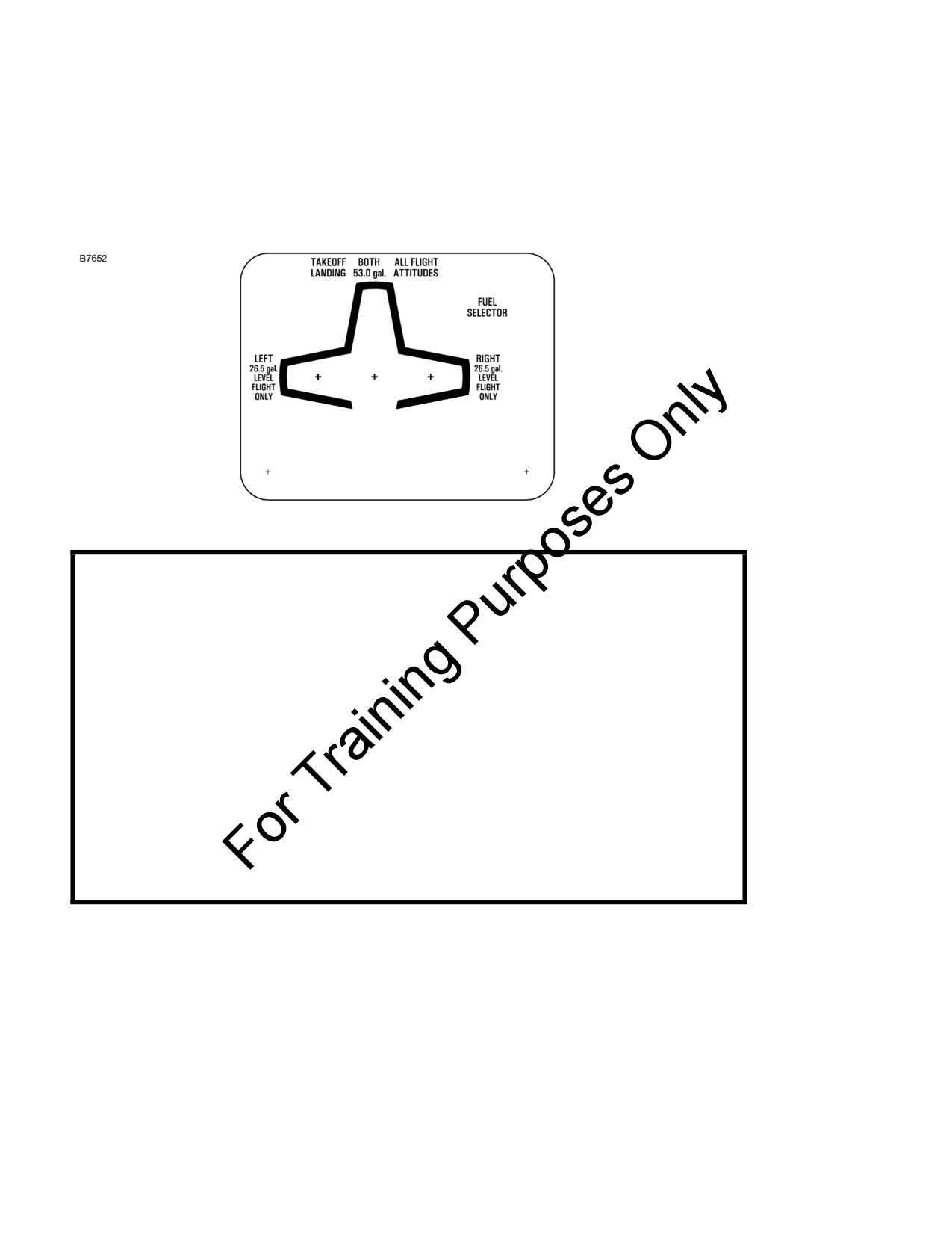
2. On the fuel selector valve:
DESPEGUE
AMBOS TODAS LAS ALTITUDES
ATERRIZAJE
200 LTS. DE VUELO
SELECTOR DE
COMBUSTIBLE
IZQUIERDA
DERECHA
100 LTS.
100 LTS.
VUELO HORIZONTAL
VUELO HORIZONTAL
SOLAMENTE
SOLAMENTE
(Continued Next Page)
FAA APPROVED
S13-6
U.S.
172SPHAUS-S13-00
CESSNA
SECTION 9 - SUPPLEMENTS
MODEL 172S NAV III
SUPPLEMENT 13
PLACARDS (Continued)
3. Near both fuel tank filler caps:
FUEL
100LL/100 MIN. GRADE AVIATION GASOLINE
CAP. 26.5 U.S. GAL. USABLE
CAP. 17.5 U.S. GAL. USABLE TO BOTTOM
OF FILLER INDICATOR TAB.
NAFTA DE AVIACIÓN GRADO 100LL/100 MIN.
CAP. 100 LTS
(26.5 GALONES ESTADOUNIDENSES)
CAP. UTILIZABLE DE 66 LTS
(17.5 GALONES ESTADOUNIDENSES)
UTILIZABLE HASTA LA PARTE INFERIOR DE LA ALETA
INDICADORA DE LLENADO.
4. On flap control indicator:
(Partial flap range with blue color code;
UP to 10o
110 KIAS
also, mechanical detent at 10o.)
(White color code; also, mechanical detent
10o to FULL
85 KIAS
at 20o.)
(Alcance del movimiento parcial del flap
HASTA 10o
110 KIAS
con código de color azul; detención
mecánica en la posición 10º.)
(Código de color blanco, detención
10o HASTA
85 KIAS
mecánica a 20º.)
EL MÁXIMO
(Continued Next Page)
FAA APPROVED
172SPHAUS-S13-00
U.S.
S13-7

SECTION 9 - SUPPLEMENTS
CESSNA
SUPPLEMENT 13
MODEL 172S NAV III
PLACARDS (Continued)
5. In baggage compartment:
54 KG MÁXIMO
EQUIPAJE ADELANTE DE LA TRABA DE LA PUERTA DE EQUIPAJE
22 KG MÁXIMO
EQUIPAJE POSTERIOR A LA TRABA DE LA PUERTA DE EQUIPAJE
MÁXIMO: 54 KG COMBINADOS
PARA INSTRUCCIONES ADICIONALES DE CARGA
VER DATOS DE PESO Y BALANCEO
6. A calibration card must be provided to indicate the accuracy of
the magnetic compass in 30° increments.
Se debe proporcionar una tarjeta de calibración para indicar la
precisión de la brújula magnética en incrementos de 30º.
(Continued Next Page)
FAA APPROVED
S13-8
U.S.
172SPHAUS-S13-00
CESSNA
SECTION 9 - SUPPLEMENTS
MODEL 172S NAV III
SUPPLEMENT 13
PLACARDS (Continued)
7. On the oil filler cap:
OIL
8 QTS
ACEITE
8 QTS
8. On control lock:
CAUTION!
CONTROL LOCK
REMOVE BEFORE STARTING ENGINE
¡ADVERTENCIA!
TRABA DE CONTROL
QUITAR ANTES DE ENCENDER EL MOTOR
9. Above the PFD:
VELOCIDAD DE MANIOBRA -105 KIAS
(Continued Next Page)
FAA APPROVED
172SPHAUS-S13-00
U.S.
S13-9

SECTION 9 - SUPPLEMENTS
CESSNA
SUPPLEMENT 13
MODEL 172S NAV III
PLACARDS (Continued)
10. On the upper right side of the aft cabin partition:
TRANSMISOR LOCALIZADOR DE EMERGENCIA
INSTALADO EN LA PARTE POSTERIOR DE ESTE TABIQUE
SERVICE EN CONFORMIDAD CON RAAC 91.207
11. On forward face of firewall adjacent to the battery:
ADVERTENCIA
24 VOLTIOS C.C.
ESTA AERONAVE ESTÁ EQUIPADA CON ALTERNADOR Y UN
SISTEMA DE CONEXIÓN A MASA NEGATIVO
RESPETAR LA POLARIDAD APROPIADA
LA POLARIDAD INVERSA DAÑARÁ LOS COMPONENTES
ELÉCTRICOS
(Continued Next Page)
FAA APPROVED
S13-10
U.S.
172SPHAUS-S13-00
CESSNA
SECTION 9 - SUPPLEMENTS
MODEL 172S NAV III
SUPPLEMENT 13
PLACARDS (Continued)
12. On the upper right instrument panel:
PROHIBIDO FUMAR
13. Near the center overhead light control:
FLOOD LIGHT
PROYECTOR DE ATERRIZAJE
FAA APPROVED
172SPHAUS-S13-00
U.S.
S13-11
SECTION 9 - SUPPLEMENTS
CESSNA
SUPPLEMENT 13
MODEL 172S NAV III
EMERGENCY PROCEDURES
There is no change to the airplane emergency procedures when used
for Argentine Certified Airplanes.
NORMAL PROCEDURES
There is no change to the airplane normal procedures when used for
Argentine Certified Airplanes.
PERFORMANCE
There is no change to the airplane performance when used for
Argentine Certified Airplanes.
FAA APPROVED
S13-12
U.S.
172SPHAUS-S13-00
CESSNA
SECTION 9 - SUPPLEMENTS
MODEL 172S NAV III
SUPPLEMENT 13
LOG OF D.N.A. ACCEPTED SUPPLEMENTS
The following list contains D.N.A. accepted supplements. Refer to Log
of Approved Supplements in the basic Pilot's Operating Handbook and
FAA Approved Airplane Flight Manual for revision status.
Supplement
Name
Equipment
Number
Installed
1
Pointer Model 3000 -11 or Model 4000-11
Emergency Locator Transmitter (ELT)
_____________
2
Reserved
3
Bendix/King KAP 140 2 Axis Autopilot
_____________
4
Winterization Kit
_____________
5
Reserved
6
Artex C406-N Emergency Locator
Transmitter (ELT)
_____________
7
Bendix/King KR
87 Automatic Direction
Finder (ADF)
_____________
8
Reserved
9
Artex ME406 Emergency Locator
Transmitter (ELT)
_____________
10
Reserved
11
Reserved
12
Reserved
13
Argentine Certified Airplanes
_____________
FAA APPROVED
172SPHAUS-S13-00
U.S.
S13-13/S13-14

CESSNA MODEL 172S
NAV III AVIONICS OPTION - KAP 140 AUTOPILOT
Serials
172S9810 thru 172S10467 and 172S10469 thru 172S10506
and
172S10508 thru 172S10639 and 172S10641 thru 172S10655
SUPPLEMENT 15
UKRAINIAN CERTIFIED AIRPLANES
SERIAL NO.
REGISTRATION NO.
This supplement must be inserted into Section 9 of the Pilot's Operating Handbook and FAA
Approved Airplane Flight Manual for Ukrainian Certified Airplanes. This supplement is approved by
the U.S. Federal Aviation Administration (FAA) on behalf of the State Aviation Administration of
Ukraine (SAA).
8 MAY 2012
COPYRIGHT © 2012
CESSNA AIRCRAFT COMPANY
WICHITA, KANSAS, USA
172SPHAUS-S15-00
U.S.
S15-1
SECTION 9 - SUPPLEMENTS
CESSNA
SUPPLEMENT 15
MODEL 172S NAV III
KAP 140 AUTOPILOT
SUPPLEMENT 15
UKRAINIAN CERTIFIED AIRPLANES
Use the Log of Effective Pages to determine the current status of this
supplement.
Pages affected by the current revision are indicated by an asterisk (*)
preceding the page number.
Supplement Status
Date
Original Issue
8 May 2012
LOG OF EFFECTIVE PAGES
Page
Page
Revision
Number
Status
Number
S15-1 thru S15-23/S15-24
Original
0
FAA APPROVED
S15-2
U.S.
172SPHAUS-S15-00
CESSNA
SECTION 9 - SUPPLEMENTS
MODEL 172S NAV III
SUPPLEMENT 15
KAP140 AUTOPILOT
SERVICE BULLETIN CONFIGURATION LIST
The following is a list of Service Bulletins that are applicable to the
operation of the airplane, and have been incorporated into this
supplement. This list contains only those Service Bulletins that are
currently active.
Number
Title
Airplane Serial
Revision
Incorporated
Effectivity
Incorporated
in Airplane
FAA APPROVED
172SPHAUS-S15-00
U.S.
S15-3
SECTION 9 - SUPPLEMENTS
CESSNA
SUPPLEMENT 15
MODEL 172S NAV III
KAP 140 AUTOPILOT
UKRAINIAN CERTIFIED AIRPLANES
GENERAL
This supplement must be placed in Section 9 of the basic Pilot’s
Operating Handbook and FAA Approved Airplane Flight Manual for
Ukrainian Certified Airplanes. The information contained herein
supplements the information of the basic Pilot’s Operating Handbook
and FAA Approved Airplane Flight Manual. Limitations, procedures,
and performance found in this supplement supersedes those found in
the basic Pilot’s Operating Handbook and FAA Approved Airplane
Flight Manual. For limitations, procedures, and performance
information not contained in this supplement, consult the basic Pilot’s
Operating Handbook and FAA Approved Airplane Flight Manual.
NOTE
In Ukraine, FAA operating rules (i.e., 14 CFR Part 91 and
14 CFR Part 135) are not applicable. The airplane must be
equipped and operated in accordance with applicable
Ukraine operational requirements.
FAA APPROVED
S15-4
U.S.
172SPHAUS-S15-00
CESSNA
SECTION 9 - SUPPLEMENTS
MODEL 172S NAV III
SUPPLEMENT 15
KAP140 AUTOPILOT
OPERATING LIMITATIONS
The following Limitations supersede and/or are in addition to the
Limitations set forth in the basic Pilot’s Operating Handbook and FAA
Approved Airplane Flight Manual:
Minimum Flight Crew:
One (1) Pilot (flying from left seat)
Maximum Number Of Seats:
Four (4)
Maximum Number Of Passengers:
Three (3) Passengers
The Nav III - KAP 140 Autopilot Avionics Option is approved for
Category I ILS approach operations only.
The Global Positioning Satellite (GPS) system is not approved for
approach.
Operation over water beyond the Maximum Glide distance from shore
is prohibited (Refer to the POH/AFM, Section 3, Figure 3-1).
A Flight Data Recorder (FDR) must be installed and operational for all
commercial transportation operations.
A portable COSPAS-SARSAT (406MHz) Emergency Radio Beacon
must be carried and operational for all operations over areas that are
difficult to access, certain regions that are rarely populated and when
flying over large bodies of water.
A HF radio must be installed and operational if airplane operates in
areas where communication through VHF radio stations cannot be
performed.
G1000 LIMITATIONS
The Garmin G1000 integrated avionics system has a minimum
operating temperature of Minus 40º C.
FAA APPROVED
172SPHAUS-S15-00
U.S.
S15-5

SECTION 9 - SUPPLEMENTS
CESSNA
SUPPLEMENT 15
MODEL 172S NAV III
KAP 140 AUTOPILOT
OPERATING LIMITATIONS (Continued)
KINDS OF OPERATION LIMITS
The following Kinds of Operations Equipment List (KOEL) identifies the
equipment required to be operational for airplane airworthiness in the
listed kind of operations for Ukrainian Certified Airplanes.
The following KOEL supersedes the KOEL located in Section 2 of the
POH/AFM.
KINDS OF OPERATIONS EQUIPMENT LIST
KIND OF OPERATION
V
I
V
F
I
F
F
R
F
R
R
R
N
N
D
I
D
I
A
G
A
G
Y
H
Y
H
System, Instrument, Equipment
and/or Function
T
T
COMMENTS
PLACARDS AND MARKINGS
1 - 172S Nav III - POH/AFM
1
1
1
1
Accessible to
pilot in flight
2 - Bendix/King KAP 140 POH
1
1
1
1
Accessible to
Autopilot Supplement
pilot in flight
3 - Garmin G1000 Cockpit
1
1
1
1
Accessible to
Reference Guide
pilot in flight
AIR CONDITIONING
1 - Forward Avionics Fan
1
1
1
1
2 - PFD Fan
0
0
0
0
3 - MFD Fan
0
0
0
0
4 - Aft Avionics Fan
1
1
1
1
(Continued Next Page)
FAA APPROVED
S15-6
U.S.
172SPHAUS-S15-00

CESSNA
SECTION 9 - SUPPLEMENTS
MODEL 172S NAV III
SUPPLEMENT 15
KAP140 AUTOPILOT
OPERATING LIMITATIONS (Continued)
KINDS OF OPERATIONS EQUIPMENT LIST (Continued)
KIND OF OPERATION
V
I
V
F
I
F
F
R
F
R
R
R
N
N
D
I
D
I
A
G
A
G
Y
H
Y
H
System, Instrument, Equipment
and/or Function
T
T
COMMENTS
COMMUNICATIONS
1 - VHF COM
1
1
1
1
2 - HF COM
1
1
1
1
* Refer to Note 1
ELECTRICAL POWER
1 - 24V Main Battery
1
1
1
1
2 - 28V Alternator
1
1
1
1
3 - 24V Standby Battery
1
1
1
1
* Refer to Note 2
4 - Main Ammeter
1
1
1
1
5 - Standby Ammeter
1
1
1
1
* Refer to Note 2
NOTE
1. A HF COM radio is required if
airplane operates in areas
where communication through VHF radio stations cannot be
performed.
2. The European Aviation Safety Agency (EASA) requires the
24V Standby Battery and Standby Ammeter to successfully
complete the pre-flight check before operating the airplane in
VFR night, IFR day, or IFR night conditions in Europe. Correct
operation of the 24V Standby Battery and Standby Ammeter is
recommended for all other operations.
(Continued Next Page)
FAA APPROVED
172SPHAUS-S15-00
U.S.
S15-7

SECTION 9 - SUPPLEMENTS
CESSNA
SUPPLEMENT 15
MODEL 172S NAV III
KAP 140 AUTOPILOT
OPERATING LIMITATIONS (Continued)
KINDS OF OPERATIONS EQUIPMENT LIST (Continued)
KIND OF OPERATION
V
I
V
F
I
F
F
R
F
R
R
R
N
N
D
I
D
I
A
G
A
G
Y
H
Y
H
System, Instrument, Equipment
and/or Function
T
T
COMMENTS
EQUIPMENT AND FURNISHINGS
1 - Seat Belt Assembly
1
1
1
1
Each Seat
Occupant
2 - Shoulder Harness
1
1
1
1
Front Seat
Occupants
3 - Portable COSPAS-SARSAT
1
1
1
1
* Refer to Note 3
Emergency Radio Beacon
FLIGHT CONTROLS
1 - Flap Position Indicator
1
1
1
1
2 - Flap Motor
1
1
1
1
3 - Elevator Trim System
1
1
1
1
4 - Elevator Trim Indicator
1
1
1
1
FUEL SYSTEM
1 - Electric Fuel Pump
1
1
1
1
2 - Fuel Quantity Indicator - L Tank
1
1
1
1
3 - Fuel Quantity Indicator - R Tank
1
1
1
1
NOTE
3. Portable COSPAS-SARSAT Emergency
Radio Beacon
required for all operations over areas that are difficult to
access, certain regions that are rarely populated and when
flying over large bodies of water.
(Continued Next Page)
FAA APPROVED
S15-8
U.S.
172SPHAUS-S15-00

CESSNA
SECTION 9 - SUPPLEMENTS
MODEL 172S NAV III
SUPPLEMENT 15
KAP140 AUTOPILOT
OPERATING LIMITATIONS (Continued)
KINDS OF OPERATIONS EQUIPMENT LIST (Continued)
KIND OF OPERATION
V
I
V
F
I
F
F
R
F
R
R
R
N
N
D
I
D
I
A
G
A
G
Y
H
Y
H
System, Instrument, Equipment
and/or Function
T
T
COMMENTS
ICE AND RAIN PROTECTION
1 - Alternate Static Air Source
0
1
1
1
2 - Alternate Induction Air System
0
1
1
1
INDICATING/RECORDING
SYSTEM
1 - Stall Warning System
1
1
1
1
2 - System Annunciator and
1
1
1
1
Warning Displays
3 - Flight Data Recorder (FDR)
1
1
1
1
*Refer to Note 4.
LANDING GEAR
1 - Wheel Fairings
0
0
0
0
Removable
LIGHTING
1 - PFD Bezel Lighting
0
0
0
1
2 - PFD Backlighting
1
1
1
*Refer to Note 5.
3 - MFD Bezel Lighting
0
0
0
1
4 - MFD Backlighting
1
1
1
*Refer to Note 6.
NOTE
4. Flight Data Recorder (FDR) required for all commercial transportation
operations.
5. PDF backlighting is required for day VFR flight if MFD backlighting has
failed. Display backup mode must be active so engine indicators are
shown.
6. MFD backlighting is required for day VFR flight if PDF backlighting has
failed. Display backup mode must be active so flight instruments are
shown.
(Continued Next Page)
FAA APPROVED
172SPHAUS-S15-00
U.S.
S15-9

SECTION 9 - SUPPLEMENTS
CESSNA
SUPPLEMENT 15
MODEL 172S NAV III
KAP 140 AUTOPILOT
OPERATING LIMITATIONS (Continued)
KINDS OF OPERATIONS EQUIPMENT LIST (Continued)
KIND OF OPERATION
V
I
V
F
I
F
F
R
F
R
R
R
N
N
D
I
D
I
A
G
A
G
Y
H
Y
H
System, Instrument, Equipment
and/or Function
T
T
COMMENTS
LIGHTING (Continued)
5 - Switch and Circuit Breaker
0
1
0
1
Panel Lighting
6 - Standby Airspeed Indicator
0
1
0
1
Internal Lighting
7 - Standby Altimeter Internal
0
1
0
1
Lighting
8 - Non-stabilized Magnetic
0
1
0
1
Compass Internal Lighting
9 - Standby Attitude Indicator
0
1
0
1
Internal Lighting
10 - Cockpit Flood Light
0
1
0
1
11 - Aircraft Position (NAV) Lights
0
1
1
1
12 - STROBE Light System
1
1
1
1
13 - BEACON Light
0
0
0
0
14 - TAXI Light
0
0
0
0
15 - LAND (Landing) Light
0
1
0
1
*Refer to Note 7.
NOTE
7. Operations for hire only. Landing light required for airplanes
equipped with single HID landing/taxi light. For airplanes
equipped with dual LED landing/taxi lights, a single LED
landing/taxi light assembly must be operating on either wing,
with all 18 LED bulbs operational.
(Continued Next Page)
FAA APPROVED
S15-10
U.S.
172SPHAUS-S15-00
CESSNA
SECTION 9 - SUPPLEMENTS
MODEL 172S NAV III
SUPPLEMENT 15
KAP140 AUTOPILOT
OPERATING LIMITATIONS (Continued)
KINDS OF OPERATIONS EQUIPMENT LIST (Continued)
KIND OF OPERATION
V
I
V
F
I
F
F
R
F
R
R
R
N
N
D
I
D
I
A
G
A
G
Y
H
Y
H
System, Instrument, Equipment
and/or Function
T
T
COMMENTS
NAVIGATION AND PITOT-
STATIC SYSTEM
1 - G1000 Airspeed Indicator
1
1
1
1
2 - Standby Airspeed Indicator
1
1
1
1
3 - G1000 Altimeter
1
1
1
1
4 - Standby Altimeter
1
1
1
1
5 - G1000 Vertical Speed
1
1
1
1
Indicator
6 - G1000 Attitude Indicator
1
1
1
1
7 - Standby Attitude Indicator
1
1
1
1
8 - G1000 Directional Indicator
1
1
1
1
(HSI)
9 - G1000 Turn Coordinator
1
1
1
1
10 - Non-stabilized Magnetic
1
1
1
1
Compass
11 - VHF Navigation Radio
A/R
A/R
A/R
A/R
As Required Per
(VOR/LOC/GS)
Procedure
12 - GPS Receiver/Navigator
A/R
A/R
A/R
A/R
As Required Per
Procedure
13 - ADF Navigation Radio
A/R
A/R
A/R
A/R
As Required Per
Procedure
(Continued Next Page)
FAA APPROVED
172SPHAUS-S15-00
U.S.
S15-11

SECTION 9 - SUPPLEMENTS
CESSNA
SUPPLEMENT 15
MODEL 172S NAV III
KAP 140 AUTOPILOT
OPERATING LIMITATIONS (Continued)
KINDS OF OPERATIONS EQUIPMENT LIST (Continued)
KIND OF OPERATION
V
I
V
F
I
F
F
R
F
R
R
R
N
N
D
I
D
I
A
G
A
G
Y
H
Y
H
System, Instrument, Equipment
and/or Function
T
T
COMMENTS
NAVIGATION AND PITOT-
STATIC SYSTEM (Continued)
14 - Marker Beacon Receiver
A/R
A/R
A/R
A/R
As Required Per
Procedure
15 - Blind Altitude Encoder
A/R
1
1
1
As Required Per
Procedure
16 - Clock
1
1
1
1
17 - Bendix King KAP 140
1
1
1
1
Autopilot
VACUUM
1 - Engine Driven Vacuum Pump
1
1
1
1
2 - Vacuum Indicator
1
1
1
1
ENGINE FUEL AND CONTROL
1 - Fuel Flow Indicator
1
1
1
1
ENGINE INDICATING
1 - Tachometer (RPM)
1
1
1
1
2 - Cylinder Head Temperature
0
0
0
0
(CHT) Indicator
3 - Oil Pressure Indicator
1
1
1
1
4 - Oil Temperature Indicator
1
1
1
1
ENGINE OIL
1 - Engine Crankcase Dipstick
1
1
1
1
FAA APPROVED
S15-12
U.S.
172SPHAUS-S15-00
CESSNA
SECTION 9 - SUPPLEMENTS
MODEL 172S NAV III
SUPPLEMENT 15
KAP140 AUTOPILOT
OPERATING LIMITATIONS (Continued)
FUEL LIMITATIONS
Approved Fuels:
100LL (ASTM-D910)
100 (Formerly 100/130) (ASTM-D910)
B91/115 (GOST 1012-72)*
NOTE
* If Russian B91/115 fuel is used, the airplane must be
equipped with either float type or Gen 3.0 fuel level
senders.
See the latest revision of Lycoming Service Instruction No.1070 for
approved fuel grades.
Fuels must contain an anti-icing fuel additive (Isopropyl Alcohol or
DiEGME) in concentrations mixed as noted in Section 8 of the POH/
AFM.
MAXIMUM APPROVED OPERATING ALTITUDE
The maximum operating barometric altitude is limited to the following:
With Passengers
3000 m (9800 feet)
Flight Crew Only (30 Minutes Maximum)
3600 m (11,800 feet)
OUTSIDE AIR TEMPERATURE LIMITS
Ground operations limits for a cold day:
Minus 40°C
Ground operations limits for a hot day:
+40°C
(Continued Next Page)
FAA APPROVED
172SPHAUS-S15-00
U.S.
S15-13
SECTION 9 - SUPPLEMENTS
CESSNA
SUPPLEMENT 15
MODEL 172S NAV III
KAP 140 AUTOPILOT
OPERATING LIMITATIONS (Continued)
TAXI OPERATIONAL LIMITS
Uncontaminated paved taxiway:
• Maximum wind velocity while taxiing:
14 m/s (27 Knots)
Paved taxiway contaminated with precipitation:
• Maximum wind velocity while taxiing:
3 m/s (5 Knots)
Refer to Section 4 of the POH/AFM for additional information on taxiing.
TAKEOFF AND LANDING OPERATIONAL LIMITS
Maximum Takeoff and Landing Altitude:
2438 m (8000 feet)
Maximum Headwind Velocity:
14 m/s (27 Knots)
Maximum Tailwind Velocity:
5 m/s (10 Knots)
Maximum crosswind velocity on
uncontaminated paved runway:
7m/s (15 Knots)
ALLOWABLE RUNWAY SURFACE CONDITIONS
1. Uncontaminated runway with paved surface.
2. Paved runway contaminated with precipitation (average depth
and types):
a. Water, less that 10.0 mm.
b. Slush, less than 10.0 mm.
c. Loose snow less than 30.0 mm.
3. Unpaved runway
a. Surface hardness not less than 7 kg/cm2 with wheel fairings
installed.
b. Surface hardness not less than 5 kg/cm2 with wheel fairings
removed.
c. Landing on contaminated unpaved runways is prohibited.
Operating with the landing gear fairings removed is recommended on
wet or unpaved runways when temperatures are near or below
freezing.
(Continued Next Page)
FAA APPROVED
S15-14
U.S.
172SPHAUS-S15-00
CESSNA
SECTION 9 - SUPPLEMENTS
MODEL 172S NAV III
SUPPLEMENT 15
KAP140 AUTOPILOT
OPERATING LIMITATIONS (Continued)
TAKEOFF AND LANDING OPERATIONAL LIMITS
(Continued)
MAXIMUM CROSSWIND ON CONTAMINATED RUNWAYS
Contaminated paved runways with:
Water, less than 10.0 mm
3 m/s (5 Knots)
Slush, less than 10.0 mm
3 m/s (5 Knots)
Loose snow, less than 30.0 mm
3 m/s (5 Knots)
Paved runway with less than 3 mm of water, snow or slush and braking
coefficient of friction(µ) of:
µ=0.3 (poor braking)
3 m/s (5 Knots)
µ=0.4 (average braking)
5 m/s (9 Knots)
µ=0.5 (good braking, dry or
equivalent to dry runway)
7 m/s (15 Knots)
NOTE
• For intermediate values of coefficient of friction
(μ),
crosswind is to be estimated by interpolation.
• Operation is prohibited on a runway covered with ice at a
coefficient of friction μ < 0.3.
FAA APPROVED
172SPHAUS-S15-00
U.S.
S15-15
SECTION 9 - SUPPLEMENTS
CESSNA
SUPPLEMENT 15
MODEL 172S NAV III
KAP 140 AUTOPILOT
OPERATING LIMITATIONS (Continued)
REQUIRED PLACARDS AND MARKINGS
Located adjacent to the left and right exterior door handles. Placard
is approximately 11.33 inches (28.78 cm) by 4.66 inches (11.84 cm)
with 1.00 inch (2.54 cm) red letters on a white background:
FAA APPROVED
S15-16
U.S.
172SPHAUS-S15-00
CESSNA
SECTION 9 - SUPPLEMENTS
MODEL 172S NAV III
SUPPLEMENT 15
KAP140 AUTOPILOT
EMERGENCY PROCEDURES
FORCED LANDINGS
If all attempts to restart the engine fail and a forced landing is imminent,
select a suitable field and prepare for the landing as discussed under
the Emergency Landing Without Engine Power checklist. Transmit
Mayday message on 121.5 MHz giving location, intentions and squawk
7700.
Before attempting an off airport landing with engine power available,
one should fly over the landing area at a safe, but low altitude, to
inspect the terrain for obstructions and surface conditions, proceeding
as discussed in the Precautionary Landing With Engine Power
checklist.
Prepare for ditching by securing or jettisoning heavy objects located in
the baggage area and collect folded coats for protection of occupants'
face at touchdown. Transmit Mayday messages on 121.5 MHz giving
location, intentions and squawk 7700. Avoid a landing flare because of
the difficulty in judging height over a water surface. The checklist
assumes the availability of power to make a precautionary water
landing. If power is not available, use of the airspeeds noted with
minimum flap extension will provide a more favorable attitude for a
power off ditching.
In a forced landing situation, do not turn off the MASTER switch,
AVIONICS switch or STBY BATT switch until a landing is assured.
Premature deactivation of the switches will disable all airplane electrical
systems.
FAA APPROVED
172SPHAUS-S15-00
U.S.
S15-17
SECTION 9 - SUPPLEMENTS
CESSNA
SUPPLEMENT 15
MODEL 172S NAV III
KAP 140 AUTOPILOT
NORMAL PROCEDURES
BEFORE STARTING ENGINE
NOTE
• When flight over water surface is intended, the airplane
must be equipped with emergency ditching flotation
equipment as required by Operation Regulations.
• Life vests must be put on before boarding the airplane.
(Continued Next Page)
FAA APPROVED
S15-18
U.S.
172SPHAUS-S15-00
CESSNA
SECTION 9 - SUPPLEMENTS
MODEL 172S NAV III
SUPPLEMENT 15
KAP140 AUTOPILOT
NORMAL PROCEDURES (Continued)
COLD WEATHER OPERATIONS
The Garmin GDU 1040 PFD/MFD requires a warm-up time of up to 30
minutes when exposed to Minus 40°C for an extended period. A warm-
up time of up to 15 minutes may be required when exposed to Minus
30°C for an extended period of time.
COLD SOAK
If extended exposure to cold weather is expected, refer to Maintenance
Manual, Model 172 Series 1996 and On, Chapter 12 Servicing, Section
12-30-00 Unscheduled Servicing-Description and Operation,
paragraph 3 Cold Soak, for procedures to prepare the airplane for cold
soak.
After extended exposure, for more than two hours, at temperatures
colder than Minus -10°C (14°F), refer to Maintenance Manual, Model
172 Series 1996 and On, Chapter 12 Servicing, Section 12-30-00
Unscheduled Servicing-Description and Operation, paragraph 3 Cold
Soak, for procedures of an airplane for preparing the airplane for flight.
Cold temperatures will affect control cable tension. See Chapter 27 of
the Maintenance Manual for flight control cable tensions. See Chapter
12 of the Maintenance Manual for information on lubrication and
greasing of moving parts. See Section 8 of the POH/AFM for correct
engine oil viscosity. See paragraphs on Cold Weather Operation in
Section 4 of the POH/AFM for additional information on procedures for
operating the airplane in cold temperatures.
When the outside temperature is less than Minus 34ºC, the airplane
batteries should be removed and stored in the warm conditions.
(Continued Next Page)
FAA APPROVED
172SPHAUS-S15-00
U.S.
S15-19
SECTION 9 - SUPPLEMENTS
CESSNA
SUPPLEMENT 15
MODEL 172S NAV III
KAP 140 AUTOPILOT
NORMAL PROCEDURES (Continued)
COLD SOAK (Continued)
Engine must be preheated before starting if engine temperature is less
than Minus 6°C. Refer to Lycoming Service Instruction No. 1505 for
recommendation of an engine preheating procedures.
When the outside temperature is less than
0°C, moisture from
combustion can freeze on the engine spark plugs if the engine does not
continue to operate after it is started. This will prevent the engine from
starting again. Preheat the engine to more than 0°C before starting the
engine again.
Preheat the engine by directing warm air into the engine cowling inlets
behind the propeller. The temperature of the preheating air should not
be more than 120°C to prevent damage to the exterior paint. Open
flames are prohibited near the airplane.
The Garmin GDU 1040 PFD/MFD requires a warm-up time of up to 30
minutes when exposed to Minus 40°C for an extended period. A warm-
up time of up to 15 minutes may be required when exposed to Minus
30°C for an extended period of time.
Before takeoff, preheat the airplane cabin to more than Minus 30°C for
correct operation of the standby altimeter. If there is no warning that an
instrument is operating incorrectly, all other instruments will operate
down to the minimum temperature of the airplane.
Before operating the airplane, it is recommended to heat the cabin to a
comfortable temperature for the cabin occupants.
FAA APPROVED
S15-20
U.S.
172SPHAUS-S15-00
CESSNA
SECTION 9 - SUPPLEMENTS
MODEL 172S NAV III
SUPPLEMENT 15
KAP140 AUTOPILOT
PERFORMANCE
TAKEOFF DISTANCE
The takeoff distance on a paved runway with no more than 3 mm of
precipitation is equal to dry runway takeoff distance.
The takeoff distance on a paved runway with precipitation greater than
3 mm is 20% greater than the dry runway takeoff distance.
LANDING DISTANCE
DRY RUNWAY - BASIC AIRFIELD
To determine the required landing distance for Ukrainian Certified
Airplanes on a dry paved runway, the dry runway landing distance listed
in Section 5, Performance, Short Field Landing Distance, Figure 5-11,
of the U.S. POH must be multiplied by 1.67.
DRY RUNWAY - DIVERSION OR ALTERNATE AIRFIELD
To determine the required landing distance for Ukrainian Certified
Airplanes on a dry paved runway, the dry runway landing distance listed
in Section 5, Performance, Short Field Landing Distance, Figure 5-11,
of the U.S. POH must be multiplied by 1.43.
CONTAMINATED RUNWAY
To determine the required landing distance for Ukrainian Certified
Airplanes on a contaminated paved runway, the Ukrainian-Factored dry
runway landing distance must be multiplied by 1.43.
WET RUNWAY
To determine the required landing distance for Ukrainian Certified
Airplanes on a wet paved runway, the Ukrainian-Factored dry runway
landing distance must be multiplied by 1.15.
For unpaved runway landing distance, refer to Section 5, Performance,
Short Field Landing Distance, Figure 5-11, of the U.S. POH for the
correction applied to grass runway landing distance.
FAA APPROVED
172SPHAUS-S15-00
U.S.
S15-21/S15-22
CESSNA
SECTION 9 - SUPPLEMENTS
MODEL 172S NAV III
SUPPLEMENT 15
KAP140 AUTOPILOT
LOG OF UKRAINE APPROVED SUPPLEMENTS
The following list contains Ukrainian SAA accepted supplements. Refer
to Log of Approved Supplements in the basic Pilot's Operating
Handbook and FAA Approved Airplane Flight Manual for revision
status.
Supplement
Name
Equipment
Number
Installed
1
Pointer Model 3000-11 or Model 4000-11
Emergency Locator Transmitter (ELT)
_____________
2
Reserved
3
Bendix/King KAP 140 2 Axis Autopilot
_____________
4
Winterization Kit
_____________
5
Reserved
6
Artex C406-N Emergency Locator
Transmitter (ELT)
_____________
7
Bendix/King KR 87 Automatic Direction
Finder (ADF)
_____________
8
Reserved
9
Artex ME406 Emergency Locator
Transmitter (ELT)
_____________
10
Reserved
11
Reserved
12
Garmin G1000 Synthetic Vision
Technology (SVT)
_____________
13
Reserved
14
Reserved
15
Ukrainian Certified Airplanes
_____________
FAA APPROVED
172SPHAUS-S15-00
U.S.
S15-23/S15-24