CESSNA 172S NAV III Skyhawk SP. Information Manual (2016) - page 3
SECTION 6
CESSNA
WEIGHT AND BALANCE/
MODEL 172S NAV III
EQUIPMENT LIST
KAP 140 AUTOPILOT
REF
WT
ARM
ITEM NO
EQUIPMENT LIST DESCRIPTION
DRAWING
LBS
INS.
25 - EQUIPMENT/FURNISHINGS
25-01-R
SEAT, PILOT, ADJUSTABLE, CLOTH/VINYL
0719025-1
33.8
41.5
COVER
25-02-O
SEAT, PILOT, ADJUSTABLE, LEATHER/VINYL
0719025-4
34.3
41.5
COVER
25-03-S
SEAT, FRONT PASSENGER, ADJUSTABLE,
0719025-1
33.8
41.5
CLOTH/VINYL COVER
25-04-O
SEAT, FRONT PASSENGER, ADJUSTABLE,
0719025-4
34.3
41.5
LEATHER/VINYL COVER
25-05-S
SEAT, REAR PASSENGER, ONE-PIECE BACK,
0719028-1
50.0
82.0
CLOTH/VINYL COVER
25-06-O
SEAT, REAR PASSENGER, ONE-PIECE BACK,
0719028-2
51.0
82.0
LEATHER/VINYL COVER
25-07-R
SEAT BELT AND SHOULDER HARNESS, INERTIA
0519031-1
5.2
50.3
REEL, AUTO ADJUST, PILOT AND FRONT
PASSENGER
25-08-S
SEAT BELT AND SHOULDER HARNESS, INERTIA
0519031-1
5.2
87.8
REEL, AUTO ADJUST, REAR SEAT
25-09-S
SUN VISOR (SET OF 2)
0514166-2
1.1
32.8
25-10-S
BAGGAGE RESTRAINT NET
2015009-7
0.5
95.0
25-11-S
CARGO TIEDOWN RINGS (SET OF 6)
0515055-6
0.2
95.0
25-12-S
TOW BAR, NOSE GEAR (STOWED)
0501019-1
1.7
124.0
25-13-R
PILOT'S OPERATING HANDBOOK AND FAA
0500832-1
2.2
50.0
APPROVED AIRPLANE FLIGHT MANUAL
(STOWED IN FRONT PASSENGER'S SEAT BACK)
25-14-R
GARMIN G1000 COCKPIT REFERENCE GUIDE
1.5
15.0
(STOWED IN COCKPIT SIDE PANEL POCKET)
25-15-O
APPROACH PLATE HOLDER
0715083-1
0.1
22.0
25-16-S
FUEL SAMPLING CUP (STOWED IN PILOT’S
S2107-1
0.1
50.0
SEAT BACK)
25-17-S
POINTER MODEL 3000-11 OR 4000-11 ELT
3940401-1
- 3000-11 ELT TRANSMITTER
3000-11-1
1.8
113.3
- 4000-11 ELT TRANSMITTER
4000-11-3
1.8
113.3
- ANTENNA AND CABLE ASSY
3003-45
0.1
122.0
25-18-O
ARTEX ME406 - 2 FREQUENCY ELT
3940458-1
2.6*
134.6*
- ELT TRANSMITTER
ME406
2.1
135.5
- ANTENNA AND CABLE ASSY
110-338
0.5
130.0
25-19-O
ARTEX C406-N - 3 FREQUENCY ELT
3940460-1
5.1*
135.0*
- ELT TRANSMITTER
C406-N
4.6
135.5
- ANTENNA AND CABLE ASSY
110-338
0.5
130.0
Figure 6-9 (Sheet 2)
6-20
U.S.
172SPHAUS-05

CESSNA
SECTION 6
MODEL 172S NAV III
WEIGHT AND BALANCE/
KAP 140 AUTOPILOT
EQUIPMENT LIST
REF
WT
ARM
ITEM NO
EQUIPMENT LIST DESCRIPTION
DRAWING
LBS
INS.
26 - FIRE PROTECTION
26-01-S
FIRE EXTINGUISHER
0501011-2
5.3*
43.0*
- FIRE EXTINGUISHER, HAND TYPE
A352GS
4.8
44.0
- MOUNTING CLAMP AND HARDWARE
1290010-1
0.5
42.2
27 - FLIGHT CONTROLS
27-01-S
DUAL CONTROLS, RIGHT SEAT
0506008-1
5.5*
12.4*
- CONTROL WHEEL, COPILOT
0513576-4
2.6
26.0
- RUDDER AND BRAKE PEDAL, COPILOT
0510402-16
1.1
6.8
27-02-A
RUDDER PEDAL EXTENSION (SET OF 2)
0501082-1
2.9
8.0
(INSTALLED ARM SHOWN)
28 - FUEL
28-01-R
AUXILIARY FUEL PUMP - 5100-00-4
0516015
1.9
9.5
28-02-R
FUEL SENDER - S3852-2
0522644
0.1
47.4
30 - ICE AND RAIN PROTECTION
30-01-S
PITOT HEAT
0523080
0.1
28.0
31 - INDICATING/RECORDING SYSTEM
31-01-S
RECORDING HOURMETER - C664503-0103
0506009
0.5
16.1
31-02-R
PNEUMATIC STALL WARNING SYSTEM
0523112
0.4
28.5
31-03-R
GEA 71 ENGINE/AIRFRAME UNIT
3930377
2.2
11.4
31-04-R
GTP 59 OUTSIDE AIR TEMPERATURE (OAT)
0518006
0.1
41.5
PROBE
32 - LANDING GEAR
32-01-R
WHEEL BRAKE AND TIRE, 6.00 X 6 MAIN (2)
0541200-7, -8
34.4*
57.8*
- WHEEL ASSY (EACH)
C163001-0104
6.2
58.2
- BRAKE ASSY (EACH)
C163030-0111
1.8
54.5
- TIRE, 6-PLY, 6.00 X 6, BLACKWALL (EACH)
C262003-0101
7.9
58.2
- TUBE, (EACH)
C262023-0102
1.3
58.2
32-02-R
WHEEL AND TIRE ASSY, 5.00 X 5 NOSE
0543062-17
9.5*
-6.8*
- WHEEL ASSY
1241156-12
3.5
-6.8
- TIRE, 6-PLY, 5.00 X 5, BLACKWALL
C262003-0202
4.6
-6.8
- TUBE
C262023-0101
1.4
-6.8
32-03-S
WHEEL FAIRING AND INSTALLATION
0541225-1
16.5*
48.1*
- WHEEL FAIRING, NOSE
0543079-3
3.5
-3.5
- WHEEL FAIRINGS, MAIN (SET OF 2)
0541223-1, -2
10.1
61.1
- BRAKE FAIRINGS (SET OF 2)
0541224-1, -2
1.1
55.6
- MOUNTING PLATE (SET OF 2)
0541220-1, -2
0.8
59.5
Figure 6-9 (Sheet 3)
172SPHAUS-05
U.S.
6-21

SECTION 6
CESSNA
WEIGHT AND BALANCE/
MODEL 172S NAV III
EQUIPMENT LIST
KAP 140 AUTOPILOT
REF
WT
ARM
ITEM NO
EQUIPMENT LIST DESCRIPTION
DRAWING
LBS
INS.
33 - LIGHTS
33-01-S
MAP LIGHT IN CONTROL WHEEL
0706015
0.2
21.5
33-02-S
COURTESY LIGHTS UNDER WING
0521101-8
0.5
61.0
33-03-S
FLASHING BEACON
0506003-6
1.4
240.7
33-04-R
STROBE LIGHT
0723628
3.4
43.3
33-05-S
LANDING AND TAXI LIGHT
0523029-7
2.4
28.7
34 - NAVIGATION
34-01-R
STANDBY AIRSPEED INDICATOR, - S3325-1
0506009
0.7
16.2
34-02-R
STANDBY ATTITUDE INDICATOR- S3326-2
0501135
2.2
14.0
34-03-R
STANDBY ALTIMETER, SENSITIVE WITH
20
0506009
0.9
14.0
FOOT MARKINGS, INCHES OF MERCURY AND
MILLBARS - S3827-1
34-04-S
ALTERNATE STATIC AIR SOURCE
0501017-1
0.2
15.5
34-05-R
COMPASS, MAGNETIC
0513262-3
0.5
18.0
34-06-R
TRANSPONDER
3940397
- GTX-33 TRANSPONDER
3910317-5
3.6
134.0
- CI 105-16 TRANSPONDER ANTENNA
3960191
0.4
86.3
34-07-R
PFD DISPLAY
3930377
- GDU-1044 DISPLAY
3910317-1
6.3
16.4
34-08-R
MFD DISPLAY
3930377
- GDU-1044 DISPLAY
3910317-1
6.3
16.4
34-09-R
ATTITUDE HEADING REFERENCE SENSOR
3940397
(AHRS)
- GRS 77 AHRS
3910317-3
2.4
134.0
- GMU 44 MAGNETOMETER
3940398
0.4
52.7
34-10-R
AIR DATA COMPUTER
3940397
- GDC 74A AIR DATA COMPUTER
3910317-6
1.7
11.4
34-11-S
BLIND YAW RATE SENSOR
3930493
1.0
15.5
(TURN COORDINATOR)
34-12-S
GDL-69A DATALINK
3940397
1.9
112.8
34-13-O
AUTOMATIC DIRECTION FINDER (ADF)
- KR 87 ADF RECEIVER
3930494
3.2
12.1
- ADF ANTENNA
3960187
4.2
39.3
34-14-O
DISTANCE MEASURING EQUIPMENT (DME)
- KN 63 REMOTE DME
3940448
2.8
154.0
- CI 105-16 DME ANTENNA
3960231
0.4
114.5
Figure 6-9 (Sheet 4)
6-22
U.S.
172SPHAUS-05

CESSNA
SECTION 6
MODEL 172S NAV III
WEIGHT AND BALANCE/
KAP 140 AUTOPILOT
EQUIPMENT LIST
REF
WT
ARM
ITEM NO
EQUIPMENT LIST DESCRIPTION
DRAWING
LBS
INS.
37 - VACUUM
37-01-R
ENGINE DRIVEN VACUUM PUMP
- VACUUM PUMP - AA3215CC
0501135
2.1
-5.0
- COOLING SHROUD
1201998-1
0.2
-5.6
- FILTER
1201075-2
0.3
2.0
- VACUUM REGULATOR
AA2H3-2
0.5
2.0
37-02-R
VACUUM TRANSDUCER - P165-5786
0501135
0.3
10.3
53 - FUSELAGE
53-01-S
REFUELING STEPS AND HANDLE
0513415-2
1.7
16.3
56 - WINDOWS
56-01-S
WINDOW, HINGED RIGHT SIDE (NET CHANGE)
0517001-40
2.3*
48.0
56-02-S
WINDOW, HINGED LEFT SIDE (NET CHANGE)
0517001-39
2.3*
48.0
61 - PROPELLER
61-01-R
FIXED PITCH PROPELLER ASSEMBLY
0550320-18
38.8*
-38.2*
- MCCAULEY 76 INCH PROPELLER
IA170E/JHA7660
35.0
-38.4
- MCCAULEY 3.5 INCH PROPELLER SPACER
C5464
3.6
-36.0
61-02-R
SPINNER INSTALLATION, PROPELLER
0550320-11
1.8*
-41.0*
- SPINNER DOME ASSEMBLY
0550236-14
1.0
-42.6
- FWD SPINNER BULKHEAD
0552231-1
0.3
-40.8
- AFT SPINNER BULKHEAD
0550321-10
0.4
-37.3
71 - POWERPLANT
71-01-R
FILTER, INDUCTION AIR
0550365
0.3
-27.5
71-02-O
WINTERIZATION KIT INSTALLATION (STOWED)
0501128-3
0.8*
-20.3*
(INSTALLED ARM SHOWN)
- BREATHER TUBE INSULATION
0552011
0.4
-13.8
- COWL INLET COVERS (INSTALLED)
0552229-3, -4
0.3
-32.0
- COWL INLET COVERS (STOWED)
0552229-3, -4
0.3
95.0
72 - ENGINES
72-01-R
ENGINE, LYCOMING IO-360-L2A
0550365
297.8*
-18.6*
Figure 6-9 (Sheet 5)
172SPHAUS-05
U.S.
6-23
SECTION 6
CESSNA
WEIGHT AND BALANCE/
MODEL 172S NAV III
EQUIPMENT LIST
KAP 140 AUTOPILOT
REF
WT
ARM
ITEM NO
EQUIPMENT LIST DESCRIPTION
DRAWING
LBS
INS.
73 - ENGINE FUEL AND CONTROL
73-01-R
FUEL FLOW TRANDUCER - 680501K
0501168
0.8
-22.6
77 - ENGINE INDICATING
77-01-R
ENGINE TACHOMETER SENSOR - 1A3C-1
0501168
0.2
-8.0
77-02-S
CYLINDER HEAD THERMOCOUPLES
0501168
0.2
-12.0
(ALL CYLINDERS) - 32DKWUE006F0126
77-03-S
0501168
0.3
-12.0
EXHAUST THERMOCOUPLES
(ALL CYLINDERS) - 86317
78 - EXHAUST
78-01-R
EXHAUST SYSTEM
9954100-1
16.3*
-20.0*
- MUFFLER AND TAILPIPE WELD ASSEMBLY
9954100-2
4.6
-22.7
- SHROUD ASSEMBLY, MUFFLER HEATER
9954100-3
0.8
-22.7
79 - OIL
79-01-R
OIL COOLER - 10877A
0550365
2.3
-11.0
79-02-R
OIL PRESSURE SENSOR - P165-5281
0550365
0.2
-12.9
79-03-R
OIL TEMPERATURE SENSOR - S2335-1
0550365
0.2
-8.5
Figure 6-9 (Sheet 6)
6-24
U.S.
172SPHAUS-05
CESSNA
SECTION 7
MODEL 172S NAV III
AIRPLANE AND SYSTEM DESCRIPTION
KAP 140 AUTOPILOT
AIRPLANE AND SYSTEMS DESCRIPTION
TABLE OF CONTENTS
Page
Introduction
7-5
Airframe
7-5
Flight Controls
7-7
Trim Systems
7-7
Instrument Panel
7-10
Pilot Panel Layout
7-10
Center Panel Layout
7-11
Right Panel Layout
7-13
Center Pedestal Layout
7-13
Flight Instruments
7-16
Attitude Indicator
7-17
Airspeed Indicator
7-18
Altimeter
7-18
Horizontal Situation Indicator
7-19
Vertical Speed Indicator
7-20
Ground Control
7-21
Wing Flap System
7-22
Landing Gear System
7-23
Baggage Compartment
7-23
Seats
7-24
Integrated Seat Belt/Shoulder Harness
7-25
Entrance Doors And Cabin Windows
7-27
Control Locks
7-28
Engine
7-29
Engine Controls
7-29
Engine Instruments
7-30
RPM (Tachometer)
7-31
Fuel Flow
7-31
Oil Pressure
7-32
Oil Temperature
7-33
(Continued Next Page)
172SPHAUS-05
U.S.
7-1
SECTION 7
CESSNA
AIRPLANE AND SYSTEM DESCRIPTION
MODEL 172S NAV III
KAP 140 AUTOPILOT
TABLE OF CONTENTS (Continued)
Page
Engine (Continued)
Cylinder Head Temperature
7-34
Exhaust Gas Temperature
7-34
New Engine Break-In And Operation
7-35
Engine Lubrication System
7-35
Ignition And Starter System
7-36
Air Induction System
7-36
Exhaust System
7-37
Fuel Injection System
7-37
Cooling System
7-37
Propeller
7-37
Fuel System
7-38
Fuel Distribution
7-39
Fuel Indicating System
7-39
Fuel Calculations
7-41
Auxiliary Fuel Pump Operation
7-43
Fuel Return System
7-44
Fuel Venting
7-44
Reduced Tank Capacity
7-44
Fuel Selector Valve
7-45
Fuel Drain Valves
7-46
Brake System
7-46
Electrical System
7-47
G1000 Annunciator Panel
7-51
Master Switch
7-51
Standby Battery Switch
7-52
Avionics Switch
7-52
Electrical System Monitoring And Annunciations
7-53
Bus Voltage (Voltmeters)
7-53
Ammeter
7-54
Standby Battery Annunciation
7-54
Low Voltage Annunciation
7-55
High Voltage Annunciation
7-56
Circuit Breakers And Fuses
7-57
External Power Receptacle
7-58
(Continued Next Page)
7-2
U.S.
172SPHAUS-05
CESSNA
SECTION 7
MODEL 172S NAV III
AIRPLANE AND SYSTEM DESCRIPTION
KAP 140 AUTOPILOT
TABLE OF CONTENTS (Continued)
Page
Lighting Systems
7-59
Exterior Lighting
7-59
Interior Lighting
7-60
Cabin Heating, Ventilating And Defrosting System
7-62
Pitot-Static System And Instruments
7-64
Vacuum System And Instruments
7-65
Attitude Indicator
7-65
Vacuum Indicator
7-65
Low Vacuum Annunciation
7-65
Clock/O.A.T. Indicator
7-67
Stall Warning System
7-67
Standard Avionics
7-68
Garmin Display Units (GDU)
7-68
Audio Panel (GMA)
7-69
Integrated Avionics Unit (GIA)
7-69
Attitude and Heading Reference System (AHRS)
and Magnetometer (GRS)
7-69
Air Data Computer (GDC)
7-70
Engine Monitor (GEA)
7-70
Transponder (GTX)
7-70
Bendix/King KAP 140 2 Axis Autopilot (if installed)
7-71
XM Weather and Radio Data Link (GDL) (if installed)
7-71
Avionics Support Equipment
7-72
Avionics Cooling Fans
7-72
Antennas
7-73
Microphone And Headset Installations
7-74
Auxiliary Audio Input Jack
7-75
12V Power Outlet
7-76
Static Dischargers
7-77
Cabin Features
7-78
Emergency Locator Transmitter (ELT)
7-78
Cabin Fire Extinguisher
7-78
Carbon Monoxide Detection System (if installed)
7-79/7-80
172SPHAUS-05
U.S.
7-3/7-4
CESSNA
SECTION 7
MODEL 172S NAV III
AIRPLANE AND SYSTEM DESCRIPTION
KAP 140 AUTOPILOT
INTRODUCTION
This section provides description and operation of the airplane and its
systems. Some equipment described herein is optional and may not be
installed in the airplane. Refer to Section 9, Supplements, for details of
other optional systems and equipment.
AIRFRAME
The airplane is an all metal, four-place, high wing, single-engine
airplane equipped with tricycle landing gear and is designed for general
utility and training purposes.
The construction of the fuselage is a conventional formed sheet metal
bulkhead, stringer, and skin design referred to as semimonocoque.
Major items of structure are the front and rear carry through spars to
which the wings are attached, a bulkhead and forgings for main landing
gear attachment at the base of the rear door posts, and a bulkhead with
attach fittings at the base of the forward door posts for the lower
attachment of the wing struts. Four engine mount stringers are also
attached to the forward door posts and extend forward to the firewall.
The externally braced wings, containing integral fuel tanks, are
constructed of a front and rear spar with formed sheet metal ribs,
doublers, and stringers. The entire structure is covered with aluminum
skin. The front spars are equipped with wing-to-fuselage and wing-to-
strut attach fittings. The aft spars are equipped with wing-to-fuselage
attach fittings, and are partial span spars. Conventional hinged ailerons
and single slot type flaps are attached to the trailing edge of the wings.
The ailerons are constructed of a forward spar containing balance
weights, formed sheet metal ribs and V type corrugated aluminum skin
joined together at the trailing edge. The flaps are constructed basically
the same as the ailerons, with the exception of the balance weights and
the addition of a formed sheet metal leading edge section.
The empennage (tail assembly) consists of a conventional vertical
stabilizer, rudder, horizontal stabilizer, and elevator. The vertical
stabilizer consists of a spar, formed sheet metal ribs and
reinforcements, a wraparound skin panel, formed leading edge skins
and a dorsal.
(Continued Next Page)
172SPHAUS-05
U.S.
7-5
SECTION 7
CESSNA
AIRPLANE AND SYSTEM DESCRIPTION
MODEL 172S NAV III
KAP 140 AUTOPILOT
AIRFRAME (Continued)
The rudder is constructed of a formed leading edge skin and spar with
attached hinge brackets and ribs, a center spar, a wrap around skin,
and a ground adjustable trim tab at the base of the trailing edge. The
top of the rudder incorporates a leading edge extension which contains
a balance weight.
The horizontal stabilizer is constructed of a forward and aft spar, ribs
and stiffeners, center, left, and right wrap around skin panels, and
formed leading edge skins. The horizontal stabilizer also contains the
elevator trim tab actuator.
Construction of the elevator consists of formed leading edge skins, a
forward spar, aft channel, ribs, torque tube and bellcrank, left upper and
lower “V” type corrugated skins, and right upper and lower “V” type
corrugated skins incorporating a trailing edge cutout for the trim tab.
The elevator tip leading edge extensions incorporate balance weights.
The elevator trim tab consists of a spar, rib, and upper and lower “V”
type corrugated skins.
7-6
U.S.
172SPHAUS-05
CESSNA
SECTION 7
MODEL 172S NAV III
AIRPLANE AND SYSTEM DESCRIPTION
KAP 140 AUTOPILOT
FLIGHT CONTROLS
The airplane's flight control system, refer to Figure 7-1, consists of
conventional aileron, rudder, and elevator control surfaces. The control
surfaces are manually operated through cables and mechanical linkage
using a control wheel for the ailerons and elevator, and rudder/brake
pedals for the rudder.
TRIM SYSTEMS
A manually operated elevator trim system is provided on this airplane,
refer to Figure 7-1. Elevator trimming is accomplished through the
elevator trim tab by utilizing the vertically mounted trim control wheel on
the center pedestal. Forward rotation of the trim wheel will trim nose
down, conversely, aft rotation will trim nose up.
(Continued Next Page)
172SPHAUS-05
U.S.
7-7

SECTION 7
CESSNA
AIRPLANE AND SYSTEM DESCRIPTION
MODEL 172S NAV III
KAP 140 AUTOPILOT
FLIGHT CONTROLS AND TRIM SYSTEM
Figure 7-1 (Sheet 1 of 2)*
7-8
U.S.
172SPHAUS-05

CESSNA
SECTION 7
MODEL 172S NAV III
AIRPLANE AND SYSTEM DESCRIPTION
KAP 140 AUTOPILOT
FLIGHT CONTROLS AND TRIM SYSTEMS
Figure 7-1 (Sheet 2)*
172SPHAUS-05
U.S.
7-9
SECTION 7
CESSNA
AIRPLANE AND SYSTEM DESCRIPTION
MODEL 172S NAV III
KAP 140 AUTOPILOT
INSTRUMENT PANEL
The instrument panel, refer to Figure 7-2, is of all metal construction
and is installed in sections so equipment can be easily removed for
maintenance. The glareshield, above and projecting aft from the
instrument panel, limits undesirable reflections on the windshield from
lighted equipment and displays mounted in the instrument panel.
The Nav III instrument panel contains the Garmin Display Unit (GDU)
Primary Flight Display (PFD) and Multifunction Display (MFD) and the
Garmin Audio Panel. For specific details regarding the instruments,
switches, circuit breakers and controls on the instrument panel, refer to
the related topics in this section.
PILOT PANEL LAYOUT
The PFD, centered on the instrument panel in front of the pilot, shows
the primary flight instruments during normal operation. During engine
start, reversionary operation
(MFD failure), or when the DISPLAY
BACKUP switch is selected, the Engine Indication System (EIS) is
shown on the PFD. Refer to the Garmin G1000 Cockpit Reference
Guide (CRG) for specific operating information.
The Standby Battery (STBY BATT) switch is found at the upper left
corner of the pilot instrument panel on an internally lighted subpanel.
The switch positions
(ARM/OFF/TEST) select the standby battery
operating modes. The rocker-type MASTER and AVIONICS switches
are found immediately below the standby battery switch.
The controls for adjusting instrument panel, equipment, and pedestal
lighting are found together on the subpanel below the MASTER and
AVIONICS switches. Refer to the INTERNAL LIGHTING paragraphs of
this section for more information.
(Continued Next Page)
7-10
U.S.
172SPHAUS-05
CESSNA
SECTION 7
MODEL 172S NAV III
AIRPLANE AND SYSTEM DESCRIPTION
KAP 140 AUTOPILOT
INSTRUMENT PANEL (Continued)
PILOT PANEL LAYOUT (Continued)
Switches for the airplane electrical systems and equipment are found
on an internally lighted subpanel found below the lower left corner of
the PFD. Each switch is labeled for function and is ON when the handle
is in the up position. Refer to the ELECTRICAL EQUIPMENT
descriptions in this section for further information.
The circuit breaker panel is found along the lower edge of the pilot's
instrument panel below the electrical equipment switch panel and pilot
control wheel column. Each circuit breaker is identified for the
equipment or function it controls and for the bus from which it receives
power. Lighting for this subpanel is controlled using the SW/CB
PANELS dimmer control. Refer to the ELECTRICAL EQUIPMENT
descriptions in this section for further information.
CENTER PANEL LAYOUT
The Garmin audio panel is found on the upper half of the center
instrument panel, immediately to the right of the PFD. A pushbutton
switch labeled DISPLAY BACKUP, to manually select display reversion
mode, is found on the lower face of the audio panel. Refer to the
Garmin G1000 CRG for operating information.
The MFD is found on the upper center panel to the right of the audio
panel. The MFD depicts EIS information along the left side of the
display and shows navigation, terrain, lightning and traffic data on the
moving map. Flight management or display configuration information
can be shown on the MFD in place of the moving map pages. Refer to
the Garmin G1000 CRG for operating information.
(Continued Next Page)
172SPHAUS-05
U.S.
7-11
SECTION 7
CESSNA
AIRPLANE AND SYSTEM DESCRIPTION
MODEL 172S NAV III
KAP 140 AUTOPILOT
INSTRUMENT PANEL (Continued)
CENTER PANEL LAYOUT (Continued)
The standby instrument cluster is in the center instrument panel below
the audio panel. A conventional (mechanical) airspeed indicator and a
sensitive aneroid altimeter are on each side of the vacuum-powered
attitude indicator. The pitot-static instruments share the airplane pitot
head and static ports with the air data computer. The attitude indicator
features a low vacuum flag to provide immediate warning of vacuum
system failure.
The Bendix/King KAP 140 2 Axis Autopilot with Altitude Preselect (if
installed) is found on the center panel below the standby instruments. A
DC electric powered turn coordinator, installed forward of the
instrument panel, and not visible to the pilot, provides a roll rate signal
to the autopilot. The autopilot receives NAV, HDG, and analog roll
steering inputs from the G1000 system. The autopilot ROL, VS, and
ALT modes operate independently from the G1000 system. Refer to
Section 9, Supplement 3 for operation of the Bendix/King KAP 140 2
Axis Autopilot.
The engine controls are found on the lower center instrument panel
below the standby instrument cluster. The controls are conventional
push-pull-type controls for throttle and mixture. Refer to the ENGINE
description in this section for operating information.
The alternate static air valve is found adjacent to the throttle control.
Refer to the PITOT-STATIC SYSTEM AND INSTRUMENTS description
in this section for operating information.
The wing flap control lever and indicator are found at the lower right
side of the center panel. Refer to the WING FLAP SYSTEM description
in this section for operating information.
(Continued Next Page)
7-12
U.S.
172SPHAUS-05
CESSNA
SECTION 7
MODEL 172S NAV III
AIRPLANE AND SYSTEM DESCRIPTION
KAP 140 AUTOPILOT
INSTRUMENT PANEL (Continued)
RIGHT PANEL LAYOUT
The Emergency Locator Transmitter (ELT) remote switch is positioned
at the upper inboard corner of the right panel adjacent to the MFD.
Refer to Section
9, Supplements
1,
6, or
9 for appropriate ELT
operating information.
The Hour (Hobbs) meter is found to the right of the ELT switch and
records engine operating time, when oil pressure is greater than 20
PSI, for maintenance purposes. Refer to the ENGINE INSTRUMENTS
description in this section for further information.
CENTER PEDESTAL LAYOUT
The center pedestal, located below the center panel, contains the
elevator trim control wheel, trim position indicator, 12V power outlet,
aux audio input jack, fuel shutoff valve, and the hand-held microphone.
The fuel selector valve handle is located at the base of the pedestal.
172SPHAUS-05
U.S.
7-13

SECTION 7
CESSNA
AIRPLANE AND SYSTEM DESCRIPTION
MODEL 172S NAV III
KAP 140 AUTOPILOT
INSTRUMENT PANEL
Figure 7-2*
7-14
U.S.
172SPHAUS-05
CESSNA
SECTION 7
MODEL 172S NAV III
AIRPLANE AND SYSTEM DESCRIPTION
KAP 140 AUTOPILOT
INSTRUMENT PANEL
1. MASTER Switch (ALT and BAT)
2. STBY BATT Switch
3. STBY BATT Test Annunciator
4. AVIONICS Switch (BUS 1 and BUS 2)
5. Primary Flight Display
6. Standby Airspeed Indicator
7. Audio Control Panel
8. Standby Attitude Indicator
9. Standby Altimeter
10.Multifunction Display
11.ELT Remote Switch/Annunciator
12.Flight Hour Recorder
13.Microphone Button
14.Bendix/King KR87 Automatic Direction Finder (if installed)
15.Glove Box
16.Cabin Heat Control
17.Cabin Air Control
18.Wing Flap Control Lever And Position Indicator
19.Bendix/King KAP 140 Autopilot (if installed)
20.Mixture Control Knob
21.Handheld Microphone
22.12V/10A Power Outlet
23.Fuel Shutoff Valve Control Knob
24.Fuel Selector Valve
25.Aux Audio Input Jack
26.Elevator Trim Control Wheel And Position Indicator
27.Throttle Control Knob (With Friction Lock)
28.ALT Static Air Valve Control
29.Yoke Mounted Map Light
30.Parking Brake Handle
31.Circuit Breaker Panel
32.Electrical Switch Panel
33.MAGNETOS/START Switch
34.DIMMING Panel
172SPHAUS-05
U.S.
7-15
SECTION 7
CESSNA
AIRPLANE AND SYSTEM DESCRIPTION
MODEL 172S NAV III
KAP 140 AUTOPILOT
FLIGHT INSTRUMENTS
The G1000 Integrated Cockpit System primary flight instrument
indications are shown on the PFD. The primary flight instruments are
arranged on the PFD in the basic T configuration. The Attitude Indicator
(AI) and Horizontal Situation Indicator (HSI) are centered vertically on
the PFD and are conventional in appearance and operation. Vertical
tape-style
(scrolling scale) indicators with fixed pointers and digital
displays, show airspeed, altitude, and vertical speed. The vertical
indicators take the place of analog indicators with a fixed circular scale
and rotating pointer.
Knobs, knob sets (two knobs on a common shaft) and membrane type
push button switches, found on the bezel surrounding each GDU
display, control COM, NAV, XPDR, and GPS avionics, set BARO
(barometric pressure), CRS (course), and HDG (heading), and work
various flight management functions. Some push button switches are
dedicated to certain functions
(keys) while other switches have
functions defined by software (softkeys). A softkey may perform various
operations or functions at various times based on software definition.
Softkeys are found along the lower bezel of the GDU displays.
(Continued Next Page)
7-16
U.S.
172SPHAUS-05
CESSNA
SECTION 7
MODEL 172S NAV III
AIRPLANE AND SYSTEM DESCRIPTION
KAP 140 AUTOPILOT
FLIGHT INSTRUMENTS (Continued)
ATTITUDE INDICATOR
The G1000 attitude indicator is shown on the upper center of the PFD.
The attitude indication data is provided by the Attitude and Heading
Reference System (AHRS). The G1000 attitude indicator provides a
horizon line that is the full width of the GDU display.
The roll index scale is conventional with 10° graduations to 30° and
then 15° graduations to 60° of roll. The roll pointer is slaved to the
airplane symbol. The pitch index scale is graduated in 5° increments
with every 10° of pitch labeled. If pitch limits are exceeded in either the
nose-up or nose-down direction, red warning chevrons will appear on
the indicator to point the way back to level flight. A small white
trapezoid located below the roll pointer moves laterally left and right to
provide the slip-skid information previously supplied by the skid
indicator ball. The trapezoid should be centered below the roll pointer
for coordinated turns. The standby (vacuum) attitude indicator is found
on the lower center instrument panel.
(Continued Next Page)
172SPHAUS-05
U.S.
7-17
SECTION 7
CESSNA
AIRPLANE AND SYSTEM DESCRIPTION
MODEL 172S NAV III
KAP 140 AUTOPILOT
FLIGHT INSTRUMENTS (Continued)
AIRSPEED INDICATOR
The G1000 vertical tape airspeed indicator is shown along the upper
left side of the PFD. The airspeed indication data is provided by the air
data computer unit. Colored bands are provided to indicate the
maximum speed, high cruise speed caution range, normal operating
range, full wing flap operating range and low airspeed awareness band.
Calculated true airspeed is displayed in a window at the bottom edge of
the airspeed tape.
The standby (pneumatic) airspeed indicator is found on the lower
center instrument panel. Colored arcs are provided to indicate the
maximum speed, high cruise speed caution range, normal operating
range, full wing flap operating range and low airspeed awareness band.
ALTIMETER
The primary altitude indicator (altimeter) is found along the right side of
the attitude indicator on the PFD. The altitude indication data is
provided by the air data computer unit. The local barometric pressure is
set using the BARO knob on the GDU displays. The GDU BARO
setting has no effect on the KAP 140 Autopilot BARO setting.
A cyan selectable altitude reference pointer, bug, is displayed on the
altimeter tape and is set using the ALT SEL knob on the GDU displays.
The altitude bug set-point is shown in a window at the top edge of the
altimeter. The ALT SEL knob has no effect on the optional KAP 140
autopilot altitude preselect or altitude hold functions.
NOTE
The optional KAP 140 autopilot altitude preselect, altitude
hold and BARO settings are completely independent of the
G1000 ALT SEL and BARO settings.
The standby (aneroid) sensitive altimeter is found on the lower center
instrument panel.
(Continued Next Page)
7-18
U.S.
172SPHAUS-05
CESSNA
SECTION 7
MODEL 172S NAV III
AIRPLANE AND SYSTEM DESCRIPTION
KAP 140 AUTOPILOT
FLIGHT INSTRUMENTS (Continued)
HORIZONTAL SITUATION INDICATOR
The Horizontal Situation Indicator (HSI) is found along the lower center
area of the PFD. The heading indication data is provided by the AHRS
and magnetometer units. The HSI combines a stabilized magnetic
direction indicator (compass card) with selectable navigation deviation
indicators for GPS or VHF navigation. The HSI is conventional in
appearance and operation.
Magnetic heading is shown numerically in a window centered above
the heading index (lubber line) at the top of the HSI. Reference index
marks are provided at 45° intervals around the compass card. A
circular segment scale below the heading window at the top of the HSI
shows half and standard rates of turn based on the length of the
magenta turn vector.
The cyan HSI heading reference pointer, bug, is set using the HDG
knob on the GDU display. The selected heading is shown digitally in a
window above the upper left 45° index mark. The selected heading will
provide control input to the autopilot, if installed, when engaged in HDG
mode.
The CDI navigation source shown on the HSI is set using the CDI
softkey to select from GPS, NAV 1 or NAV 2 inputs. The course
reference pointer is set using the CRS knob on the GDU display. The
selected course is shown digitally in a window above the upper right
45° index mark. The selected navigation source will provide control
input to the autopilot, if installed, when engaged in NAV, APR or REV
mode and it is receiving a navigation signal from the selected GPS or
VHF NAV radios.
(Continued Next Page)
172SPHAUS-05
U.S.
7-19
SECTION 7
CESSNA
AIRPLANE AND SYSTEM DESCRIPTION
MODEL 172S NAV III
KAP 140 AUTOPILOT
FLIGHT INSTRUMENTS (Continued)
HORIZONTAL SITUATION INDICATOR (Continued)
WARNING
WHEN THE KAP 140 AUTOPILOT IS ENGAGED IN NAV,
APR OR REV OPERATING MODES, IF THE HSI
NAVIGATION SOURCE IS CHANGED FROM GPS TO
NAV1, AUTOMATICALLY OR MANUALLY (USING THE
CDI SOFTKEY), OR MANUALLY FROM NAV2 TO GPS,
THE CHANGE WILL INTERRUPT THE NAVIGATION
SIGNAL TO THE AUTOPILOT AND WILL CAUSE THE
AUTOPILOT TO REVERT TO ROL MODE OPERATION.
NO WARNING CHIME OR PFD ANNUNCIATION IS
PROVIDED. THE PREVIOUSLY SELECTED MODE
SYMBOL SHOWN ON THE AUTOPILOT DISPLAY WILL
BE FLASHING TO SHOW THE REVERSION TO ROL
MODE OPERATION. IN ROL MODE, THE AUTOPILOT
WILL ONLY KEEP THE WINGS LEVEL AND WILL NOT
CORRECT THE AIRPLANE HEADING OR COURSE. SET
THE HDG BUG TO THE CORRECT HEADING AND
SELECT THE CORRECT NAVIGATION SOURCE ON
THE HSI USING THE CDI SOFTKEY BEFORE
ENGAGING THE AUTOPILOT IN ANY OTHER
OPERATING MODE.
VERTICAL SPEED INDICATOR
The Vertical Speed Indicator (VSI) tape is found on the right side of the
altimeter display along the upper right side of the PFD. The vertical
speed pointer moves up and down the fixed VSI scale and shows the
rate of climb or descent in digits inside the pointer. The VSI tape has a
notch on the right edge at the 0 feet/min index for reference. Rate of
descent is shown with a negative sign in front of the digits. Vertical
speed must exceed 100 feet/min in climb or descent before digits will
appear in the VSI pointer.
7-20
U.S.
172SPHAUS-05
CESSNA
SECTION 7
MODEL 172S NAV III
AIRPLANE AND SYSTEM DESCRIPTION
KAP 140 AUTOPILOT
GROUND CONTROL
Effective ground control while taxiing is accomplished through
nosewheel steering by using the rudder pedals; left rudder pedal to
steer left and right rudder pedal to steer right. When a rudder pedal is
depressed, a spring loaded steering bungee, which is connected to the
nose gear and to the rudder bars, will turn the nosewheel through an
arc of approximately 10° each side of center. By applying either left or
right brake, the degree of turn may be increased up to 30° each side of
center.
Moving the airplane by hand is most easily accomplished by attaching
a towbar to the nose gear strut. If a towbar is not available, or pushing
is required, use the wing struts as push points. Do not use the vertical
or horizontal surfaces to move the airplane. If the airplane is to be
towed by vehicle, never turn the nosewheel more than 30° either side
of center or structural damage to the nose gear could result.
The minimum turning radius of the airplane, using differential braking
and nosewheel steering during taxi, is approximately 27 feet. To obtain
a minimum radius turn during ground handling, the airplane may be
rotated around either main landing gear by pressing down on a tailcone
bulkhead just forward of the horizontal stabilizer to raise the nosewheel
off the ground. Care should be exercised to ensure that pressure is
exerted only on the bulkhead area and not on skin between the
bulkheads. Pressing down on the horizontal stabilizer to raise the
nosewheel off the ground is not recommended.
172SPHAUS-05
U.S.
7-21

SECTION 7
CESSNA
AIRPLANE AND SYSTEM DESCRIPTION
MODEL 172S NAV III
KAP 140 AUTOPILOT
WING FLAP SYSTEM
The single slot type wing flaps, refer to Figure 7-3, are extended or
retracted by positioning the wing flap control lever on the instrument
panel to the desired flap deflection position. The wing flap control lever
is moved up or down in a slotted panel that provides mechanical stops
at the 10°, 20° and FULL positions. To change flap setting, the wing flap
control lever is moved to the right to clear mechanical stops at the 10°
and 20° positions. A scale and pointer to the left of the wing flap control
lever indicates flap travel in degrees. The wing flap system circuit is
protected by a 10-ampere circuit breaker, labeled FLAP, on the left side
of the circuit breaker panel.
Figure 7-3*
7-22
U.S.
172SPHAUS-05
CESSNA
SECTION 7
MODEL 172S NAV III
AIRPLANE AND SYSTEM DESCRIPTION
KAP 140 AUTOPILOT
LANDING GEAR SYSTEM
The landing gear is of the tricycle type, with a steerable nosewheel and
two main wheels. Wheel fairings are standard equipment for both the
main wheels and nosewheel. Shock absorption is provided by the
tubular spring steel main landing gear struts and the air/oil nose gear
shock strut. Each main gear wheel is equipped with a hydraulically-
actuated disc type brake on the inboard side of each wheel.
BAGGAGE COMPARTMENT
The baggage compartment consists of two areas, one extending from
behind the rear passengers seat to the aft cabin bulkhead, and an
additional area aft of the bulkhead. Access to both baggage areas is
gained through a lockable baggage door on the left side of the airplane,
or from within the airplane cabin. A baggage net with tiedown straps is
provided for securing baggage and is attached by tying the straps to
tiedown rings provided in the airplane. For baggage area and door
dimensions, refer to Section 6.
172SPHAUS-05
U.S.
7-23
SECTION 7
CESSNA
AIRPLANE AND SYSTEM DESCRIPTION
MODEL 172S NAV III
KAP 140 AUTOPILOT
SEATS
The seating arrangement consists of two vertically adjusting crew seats
for the pilot and front seat passenger, and a single bench seat with
adjustable back for rear seat passengers.
Seats used for the pilot and front seat passenger are adjustable
forward and aft, and up and down. Additionally, the angle of the seat
back is infinitely adjustable.
Forward and aft adjustment is made using the handle located below the
center of the seat frame. To position the seat, lift the handle, slide the
seat into position, release the handle and check that the seat is locked
in place. To adjust the height of the seat, rotate the large crank under
the right corner of the seat until a comfortable height is obtained. To
adjust the seat back angle, pull up on the release button, located in
center front of seat, just under the seat bottom, position the seat back
to the desired angle, and release the button. When the seat is not
occupied, the seat back will automatically fold forward whenever the
release button is pulled up.
The rear passenger seat consists of a fixed, one piece seat bottom and
a three-position reclining back. The reclining back is adjusted by a lever
located below the center of the seat frame. To adjust the seat back,
raise the lever, position the seat back to the desired angle, release the
lever, and check that the seat back is securely locked in place.
Headrests are installed on both the front and rear seats. To adjust the
headrest, apply enough pressure to it to raise or lower it to the desired
level.
7-24
U.S.
172SPHAUS-05
CESSNA
SECTION 7
MODEL 172S NAV III
AIRPLANE AND SYSTEM DESCRIPTION
KAP 140 AUTOPILOT
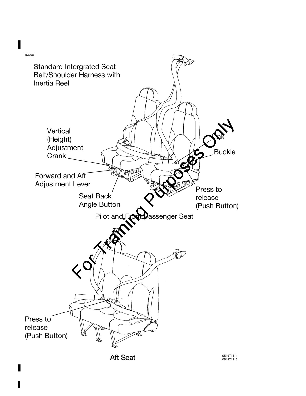
INTEGRATED SEAT BELT/SHOULDER HARNESS
All seat positions are equipped with integrated seat belts/shoulder
harness assemblies, refer to Figure 7-4. The design incorporates an
overhead inertia reel for the shoulder portion, and a retractor assembly
for the lap portion of the belt. This design allows for complete freedom
of movement of the upper torso area while providing restraint in the lap
belt area. In the event of a sudden deceleration, reels lock up to provide
positive restraint for the user.
In the front seats, the inertia reels are located on the centerline of the
upper cabin area. In the rear seats, the inertia reels are located
outboard of each passenger in the upper cabin.
To use the integrated seat belt/shoulder harness, grasp the link with
one hand, and, in a single motion, extend the assembly and insert into
the buckle. Positive locking has occurred when a distinctive “snap”
sound is heard.
Proper locking of the lap belt can be verified by ensuring that the belts
are allowed to retract into the retractors and the lap belt is snug and low
on the waist as worn normally during flight. No more than one
additional inch of belt should be able to be pulled out of the retractor
once the lap belt is in place on the occupant. If more than one
additional inch of belt can be pulled out of the retractor, the occupant is
too small for the installed restraint system and the seat should not be
occupied until the occupant is properly restrained.
Removal is accomplished by pressing the release button on the buckle
and pulling out and up on the harness. Spring tension on the inertia reel
will automatically stow the harness.
172SPHAUS-05
U.S.
7-25
SECTION 7
CESSNA
AIRPLANE AND SYSTEM DESCRIPTION
MODEL 172S NAV III
KAP 140 AUTOPILOT
INTEGRATED SEAT BELT/SHOULDER HARNESS
Figure 7-4*
7-26
U.S.
172SPHAUS-05
CESSNA
SECTION 7
MODEL 172S NAV III
AIRPLANE AND SYSTEM DESCRIPTION
KAP 140 AUTOPILOT
ENTRANCE DOORS AND CABIN WINDOWS
Entry to and exit from the airplane is accomplished through either of
two entry doors, one on each side of the cabin, at the front seat
positions, refer to Section 6 for cabin and cabin door dimensions. The
doors incorporate a recessed exterior door handle, a conventional
interior door handle, a key operated door lock, left door only, a door
stop mechanism, and openable windows in both the left and right
doors.
NOTE
The door latch design on this model requires that the
outside door handle on the pilot and front passenger doors
be extended out whenever the doors are open. When
closing the door, do not attempt to push the door handle in
until the door is fully shut.
To open the doors from outside the airplane, utilize the recessed door
handle near the aft edge of either door by grasping the forward edge of
the handle and pulling outboard. To close or open the doors from inside
the airplane, use the combination door handle and arm rest. The inside
door handle has three positions and a placard at its base which reads
OPEN, CLOSE, and LOCK. The handle is spring loaded to the CLOSE
(up) position. When the door has been pulled shut and latched, lock it
by rotating the door handle forward to the LOCK position (flush with the
arm rest). When the handle is rotated to the LOCK position, an over
center action will hold it in that position. Both cabin doors should be
locked prior to flight, and should not be opened intentionally during
flight.
NOTE
Accidental opening of a cabin door in flight, due to improper
closing, does not constitute a need to land the airplane. The
best procedure is to set up the airplane in a trimmed
condition at approximately 75 KIAS, momentarily shove the
door outward slightly, and forcefully close and lock the door.
(Continued Next Page)
172SPHAUS-05
U.S.
7-27
SECTION 7
CESSNA
AIRPLANE AND SYSTEM DESCRIPTION
MODEL 172S NAV III
KAP 140 AUTOPILOT
ENTRANCE DOORS AND CABIN WINDOWS
(Continued)
Exit from the airplane is accomplished by rotating the door handle from
the LOCK position, past the CLOSE position, aft to the OPEN position
and pushing the door open. To lock the airplane, lock the right cabin
door with the inside handle, close the left cabin door, and using the
ignition key, lock the door.
The left and right cabin doors are equipped with openable windows
which are held in the closed position by a detent equipped latch on the
lower edge of the window frame. To open the windows, rotate the latch
upward. Each window is equipped with a spring-loaded retaining arm
which will help rotate the window outward, and hold it there. If required,
either window may be opened at any speed up to 163 KIAS. The rear
side windows and rear windows are of the fixed type and cannot be
opened.
CONTROL LOCKS
A control lock is provided to lock the aileron and elevator control
surfaces to prevent damage to these systems by wind buffeting while
the airplane is parked. The lock consists of a shaped steel rod and flag.
The flag identifies the control lock and cautions about its removal
before starting the engine. To install the control lock, align the hole in
the top of the pilot’s control wheel shaft with the hole in the top of the
shaft collar on the instrument panel and insert the rod into the aligned
holes. Installation of the lock will secure the ailerons in a neutral
position and the elevators in a slightly trailing edge down position.
Proper installation of the lock will place the flag over the ignition switch.
In areas where high or gusty winds occur, a control surface lock should
be installed over the vertical stabilizer and rudder. The control lock and
any other type of locking device should be removed prior to starting the
engine.
7-28
U.S.
172SPHAUS-05
CESSNA
SECTION 7
MODEL 172S NAV III
AIRPLANE AND SYSTEM DESCRIPTION
KAP 140 AUTOPILOT
ENGINE
The airplane is powered by a direct drive, horizontally opposed, four
cylinder, overhead valve, air cooled, fuel injected engine with a wet
sump lubrication system. The engine is a Lycoming Model IO-360-L2A
rated at 180 horsepower at 2700 RPM. Major accessories include a
starter and belt driven alternator mounted on the front of the engine,
dual magnetos, vacuum pump, engine driven fuel pump, and a full flow
oil filter mounted on the rear of the engine accessory case.
ENGINE CONTROLS
Engine power is set using the throttle control. The throttle control is a
smooth black knob located at the center of the instrument panel below
the standby instruments. The throttle control is configured so that the
throttle is open in the forward position and closed in the full aft position.
A friction lock, located at the base of the throttle, is operated by rotating
the lock clockwise to increase friction or counterclockwise to decrease
friction.
Engine fuel mixture is controlled by the mixture control. The mixture
control is a red knob, with raised points around the circumference,
located immediately to the right of the throttle control and is equipped
with a lock button in the end of the knob. The rich position is full
forward, and full aft is the idle cutoff position. For small adjustments, the
control may be moved forward by rotating the knob clockwise, and aft
by rotating the knob counterclockwise. For rapid or large adjustments,
the knob may be moved forward or aft by depressing the lock button in
the end of the control, and then positioning the control as desired.
(Continued Next Page)
172SPHAUS-05
U.S.
7-29
SECTION 7
CESSNA
AIRPLANE AND SYSTEM DESCRIPTION
MODEL 172S NAV III
KAP 140 AUTOPILOT
ENGINE (Continued)
ENGINE INSTRUMENTS
The G1000 Engine Indication System
(EIS) provides graphical
indicators and numeric values for engine, fuel, and electrical system
parameters to the pilot. The EIS is shown in a vertical strip on the left
side of the PFD during engine starts and on the MFD during normal
operation. If either the MFD or PFD fails during flight, the EIS is shown
on the remaining display.
The EIS consists of three pages that are selected using the ENGINE
softkey. The ENGINE page provides indicators for Tachometer (RPM),
Fuel Flow (FFLOW GPH), Oil Pressure (OIL PRES), Oil Temperature
(OIL TEMP), Exhaust Gas Temperature (EGT), Vacuum (VAC), Fuel
Quantity (FUEL QTY GAL), Engine Hours (ENG HRS), Electrical Bus
Voltages (VOLTS), and Battery Currents (AMPS). When the ENGINE
softkey is pressed, the LEAN and SYSTEM softkeys appear adjacent to
the ENGINE softkey. The LEAN page provides simultaneous indicators
for Exhaust Gas Temperature
(EGT
°F) and Cylinder Head
Temperature (CHT °F) on all cylinders to be used for adjusting, or
leaning, the fuel/air mixture along with a digital value for FFLOW GPH
and a indicator for FUEL QTY GAL. The SYSTEM page provides
numerical values for parameters on the ENGINE page that are shown
as indicators only. The SYSTEM page also provides a digital value for
Fuel Used (GAL USED) and Fuel Remaining (GAL REM).
The engine and airframe unit, located forward of the instrument panel,
receives signals from the engine/system sensors for the parameters
that are being monitored. The engine and airframe unit provides data to
the EIS, which displays the data for the ENGINE page described on the
following pages.
(Continued Next Page)
7-30
U.S.
172SPHAUS-05
CESSNA
SECTION 7
MODEL 172S NAV III
AIRPLANE AND SYSTEM DESCRIPTION
KAP 140 AUTOPILOT
ENGINE (Continued)
ENGINE INSTRUMENTS (Continued)
RPM (TACHOMETER)
Engine speed (RPM) is shown by the tachometer indicator found on all
EIS pages. The tachometer indicator uses a circular scale with moving
pointer and a digital value. The pointer moves through a range from 0
to 3000 RPM. The numerical RPM value is displayed in increments of
10 RPM in white numerals below the pointer.
The normal engine speed operating limit (top of green arc) changes
with altitude. For standard-day conditions, between sea level and 5000
feet, 2500 RPM is the upper limit of the normal operating range. From
5000 feet to 10,000 feet, 2600 RPM is the top of the normal range. And
above 10,000 feet, 2700 RPM is the upper limit of the normal operating
range.
When engine speed is 2780 RPM or more, the pointer, digital value,
and label (RPM) turn red to show engine speed is more than the limit.
The digital value and label
(RPM) will flash. The engine speed
(tachometer) is displayed in the same configuration and location on the
LEAN and SYSTEM pages. If engine speed becomes 2780 RPM or
more, while on the LEAN or SYSTEM page, the display will return to
the ENGINE page.
A speed sensor, mounted on the engine tachometer drive accessory
pad, provides a digital signal to the engine and airframe unit which
processes and outputs the RPM data to the EIS. A red X through the
RPM indicator shows the indicating system is inoperative.
(Continued Next Page)
172SPHAUS-05
U.S.
7-31
SECTION 7
CESSNA
AIRPLANE AND SYSTEM DESCRIPTION
MODEL 172S NAV III
KAP 140 AUTOPILOT
ENGINE (Continued)
ENGINE INSTRUMENTS (Continued)
FUEL FLOW
Fuel flow is shown on the ENGINE page by the FFLOW GPH horizontal
indicator. The indicator range is from 0 to 20 gallons per hour (GPH)
with 2 GPH graduations, with a green band from 0 to 12 GPH. A white
pointer shows the measured fuel flow.
A digital value for FFLOW GPH is included on both the EIS LEAN and
SYSTEM pages.
The fuel flow transducer is located in the engine fuel injection system
between the fuel/air control unit
(servo) and the fuel distribution
manifold (flow divider). The transducer provides a signal to the engine
display that is processed and shown as fuel flow (FFLOW) on the EIS
pages. A red X through the indicator means the indicating system is
inoperative.
OIL PRESSURE
Engine oil pressure is shown on the ENGINE page by the OIL PRES
horizontal indicator. The indicator range is 0 to 120 PSI with a red band
from 0 to 20 PSI, a green band from 50 to 90 PSI (normal operating
range) and a red band from 115 to 120 PSI. A white pointer indicates
actual oil pressure. Oil pressure is shown numerically on the SYSTEM
page.
When oil pressure is 0 to 20 PSI or 115 to 120 PSI, the pointer, digital
value, and label (OIL PRES) will change to red to show that oil pressure
is outside normal limits. If oil pressure exceeds either the upper or
lower limit while on the LEAN or SYSTEM page, the EIS will return to
the ENGINE page.
When the engine speed (RPM) is in the green arc and the oil
temperature is in the green band, the oil pressure should be in the
green band. If oil pressure is below the green band or above the green
band, adjust the engine speed to maintain adequate oil pressure. When
engine speed is at idle or near idle, the oil pressure indication must be
above the lower red band. With the engine at normal operating oil
temperature, and engine speed at or close to idle, oil pressure below
the green band, but above the lower red band, is acceptable.
(Continued Next Page)
7-32
U.S.
172SPHAUS-05
CESSNA
SECTION 7
MODEL 172S NAV III
AIRPLANE AND SYSTEM DESCRIPTION
KAP 140 AUTOPILOT
ENGINE (Continued)
ENGINE INSTRUMENTS (Continued)
OIL PRESSURE (Continued)
In cold weather, the oil pressure will initially be high (close to the upper
red band when the engine is started). As the engine and oil warm up,
the oil pressure will come down into the green band range.
The oil pressure transducer, connected to the engine forward oil
pressure port, provides a signal to the engine display that is processed
and shown as oil pressure. A separate low oil pressure switch causes
an OIL PRESSURE annunciation on the PFD when oil pressure is 0 to
20 PSI. A red X through the oil pressure indicator means that the
indicating system is inoperative.
OIL TEMPERATURE
Engine oil temperature is shown on the ENGINE page by the OIL
TEMP horizontal indicator. The indicator range is from 75°F to 250°F
with a green band (normal operating range) from 100°F to 245°F and a
red band from 245°F to 250°F. A white pointer indicates actual oil
temperature. Oil temperature is displayed numerically on the SYSTEM
page.
When oil temperature is in the red band, 245°F to 250°F, the pointer
and OIL TEMP turn red and flash to show oil temperature is higher than
the limit. If oil temperature becomes hotter than 245°F while on the
LEAN or SYSTEM page, the display will default to the ENGINE page.
The oil temperature sensor is installed in the engine oil filter adapter
and provides a signal to the engine display that is processed and
shown as oil temperature. A red X through the indicator shows that the
indicating system is inoperative.
(Continued Next Page)
172SPHAUS-05
U.S.
7-33
SECTION 7
CESSNA
AIRPLANE AND SYSTEM DESCRIPTION
MODEL 172S NAV III
KAP 140 AUTOPILOT
ENGINE (Continued)
ENGINE INSTRUMENTS (Continued)
CYLINDER HEAD TEMPERATURE
Cylinder Head Temperature (CHT) for all four cylinders are shown on
the LEAN page. The cylinder with the hottest CHT is indicated by a
cyan bar graph. The indicator range is from 100°F to 500°F with a
normal operating range from 200°F to 500°F and a warning range (red
line) at 500°F. When the CHT is 500°F or hotter, the bar segments,
CHT label and °F digital value will change to red to show that the CHT
is greater than the limit.
A thermocouple is installed in each cylinder head and provides a signal
to the engine display that is processed and shown as CHT on the EIS
LEAN page. The LEAN page will show a red X over any cylinder that
has a probe or wiring failure.
EXHAUST GAS TEMPERATURE
Exhaust Gas Temperature (EGT) is shown on the ENGINE page by the
EGT horizontal indicator. The indicator range is from 1250°F to 1650°F
with graduations every 50°F. The white pointer indicates relative EGT
with the number of the hottest cylinder displayed inside the pointer. If a
cylinder EGT probe or wiring failure occurs for the hottest EGT, the next
hottest EGT will be displayed.
The EGT for all four cylinders is shown on the LEAN page of the EIS.
The hottest cylinder is indicated by the cyan bar graph. The EGT for a
particular cylinder may be shown by using the CYL SLCT softkey to
select the desired cylinder. Automatic indication of the hottest cylinder
will resume a short time after the CYL SLCT is last selected. The LEAN
page will show a red X over a cylinder that has a probe or wiring failure.
A thermocouple is installed in the exhaust pipe of each cylinder which
measures EGT and provides a signal to the engine display that is
processed and shown as EGT on the EIS LEAN page.
(Continued Next Page)
7-34
U.S.
172SPHAUS-05
CESSNA
SECTION 7
MODEL 172S NAV III
AIRPLANE AND SYSTEM DESCRIPTION
KAP 140 AUTOPILOT
ENGINE (Continued)
NEW ENGINE BREAK-IN AND OPERATION
The engine run-in was accomplished at the factory and is ready for the
full range of use. It is suggested that cruising be accomplished at 75%
power as much as practicable until a total of 50 hours has accumulated
or oil consumption has stabilized. This will ensure proper seating of the
piston rings.
ENGINE LUBRICATION SYSTEM
The engine utilizes a full pressure, wet sump type lubrication system
with aviation grade oil as the lubricant. The capacity of the engine
sump, located on the bottom of the engine, is eight quarts with one
additional quart contained in the engine oil filter. Oil is drawn from the
sump through a filter screen on the end of a pickup tube to the engine
driven oil pump. Oil from the pump passes through a full-flow oil filter, a
pressure relief valve at the rear of the right oil gallery, and a
thermostatically controlled remote oil cooler. Oil from the remote cooler
is then circulated to the left oil gallery. The engine parts are then
lubricated by oil from the galleries. After lubricating the engine, the oil
returns to the sump by gravity. The filter adapter in the full-flow filter is
equipped with a bypass valve which will cause lubricating oil to bypass
the filter in the event the filter becomes plugged, or the oil temperature
is extremely cold.
An oil dipstick/filler tube is located at the right rear of the engine case.
The oil dipstick/filler tube is accessed through a door located on the
right side of the engine cowling. The engine should not be operated on
less than five quarts of oil. To minimize loss of oil through the breather,
fill to eight quarts for normal flights of less than three hours. For
extended flight, fill to eight quarts (dipstick indication only). For engine
oil grade and specifications, refer to Section 8 of this POH.
(Continued Next Page)
172SPHAUS-05
U.S.
7-35
SECTION 7
CESSNA
AIRPLANE AND SYSTEM DESCRIPTION
MODEL 172S NAV III
KAP 140 AUTOPILOT
ENGINE (Continued)
IGNITION AND STARTER SYSTEM
Engine ignition is provided by two engine driven magnetos, and two
spark plugs in each cylinder. The left magneto fires the upper left and
lower right spark plugs, and the right magneto fires the lower left and
upper right spark plugs. Normal operation is conducted with both
magnetos due to the more complete burning of the fuel/air mixture with
dual ignition.
Ignition and starter operation is controlled by a rotary-type switch
located on the left switch and control panel. The MAGNETOS switch is
labeled clockwise, OFF, R, L, BOTH, and START. The engine should
be operated on both magnetos (BOTH position) except for magneto
checks. The R and L positions are for checking purposes and
emergency use only. When the MAGNETOS switch is rotated to the
spring-loaded START position, with the MASTER switch in the ON
position, the starter contactor is closed and the starter, now energized,
will crank the engine. When the switch is released, it will automatically
return to the BOTH position.
AIR INDUCTION SYSTEM
The engine air induction system receives ram air through an intake on
the lower front portion of the engine cowling. The intake is covered by
an air filter which removes dust and other foreign matter from the
induction air. Airflow passing through the filter enters an air box, which
is equipped with a spring-loaded alternate air door. If the air induction
filter should become blocked, suction created by the engine will open
the door and draw unfiltered air from inside the lower cowl area. An
open alternate air door will result in an approximate 10% power loss at
full throttle. After passing through the air box, induction air enters a fuel/
air control unit under the engine, and is then ducted to the engine
cylinders through intake manifold tubes.
(Continued Next Page)
7-36
U.S.
172SPHAUS-05
CESSNA
SECTION 7
MODEL 172S NAV III
AIRPLANE AND SYSTEM DESCRIPTION
KAP 140 AUTOPILOT
ENGINE (Continued)
EXHAUST SYSTEM
Exhaust gas from each cylinder passes through a riser assembly to a
common muffler, located below the engine, and then overboard through
a single tailpipe. Outside air is supplied to a shroud constructed around
the outside of the muffler to form a heating chamber. The air heated by
the shroud is then supplied to the cabin.
FUEL INJECTION SYSTEM
The engine is equipped with a fuel injection system. The system is
comprised of an engine driven fuel pump, fuel/air control unit, fuel
manifold, fuel flow indicator, and air-bleed type injector nozzles.
Fuel is delivered by the engine driven fuel pump to the fuel/air control
unit. The fuel/air control unit correctly proportions the fuel flow to the
induction air flow. After passing through the control unit, induction air is
delivered to the cylinders through the intake manifold tubes and
metered fuel is delivered to a fuel manifold (flow divider). The fuel
manifold, through spring tension on a diaphragm and valve, evenly
distributes the fuel to an air-bleed type injector nozzle in the intake
valve chamber of each cylinder. A turbine-type fuel flow transducer
mounted between the fuel/air control unit and the fuel distribution unit
produces a digital signal that displays fuel flow on the EIS pages.
COOLING SYSTEM
Ram air for engine cooling enters through two intake openings in the
front of the engine cowling. The cooling air is directed from above the
engine, around the cylinders and other areas of the engine by baffling,
and then exits through an opening at the bottom aft edge of the engine
cowling.
A winterization kit is available for the airplane. Refer to Section 9,
Supplement 4 for description and operating information.
PROPELLER
The airplane is equipped with a two bladed, fixed pitch, one-piece
forged aluminum alloy propeller which is anodized to retard corrosion.
The propeller is 76 inches in diameter.
172SPHAUS-05
U.S.
7-37
SECTION 7
CESSNA
AIRPLANE AND SYSTEM DESCRIPTION
MODEL 172S NAV III
KAP 140 AUTOPILOT
FUEL SYSTEM
The airplane fuel system, refer to Figure 7-6, consists of two vented
integral fuel tanks
(one tank in each wing), three-position selector
valve, fuel reservoir tank, electrically-driven auxiliary fuel pump, fuel
shutoff valve, and a fuel strainer. The engine-mounted portion of the
system consists of the engine driven fuel pump, a fuel/air control unit,
fuel flow transducer, a fuel distribution valve (flow divider) and fuel
injection nozzles.
WARNING
UNUSABLE FUEL LEVELS FOR THIS AIRPLANE WERE
DETERMINED IN ACCORDANCE WITH FEDERAL
AVIATION REGULATIONS. FAILURE TO OPERATE THE
AIRPLANE IN COMPLIANCE WITH FUEL LIMITATIONS
SPECIFIED IN SECTION 2 MAY FURTHER REDUCE THE
AMOUNT OF FUEL AVAILABLE IN FLIGHT.
FUEL QUANTITY DATA IN U.S. GALLONS
FUEL LEVEL
TOTAL USABLE
FUEL
(QUANTITY
TOTAL
TOTAL
ALL FLIGHT
TANKS
EACH TANK)
FUEL
UNUSABLE
CONDITIONS
Two
Full (28.0)
56.0
3.0
53.0
Two
Reduced (19.0)
38.0
3.0
35.0
Figure 7-5*
(Continued Next Page)
7-38
U.S.
172SPHAUS-05
CESSNA
SECTION 7
MODEL 172S NAV III
AIRPLANE AND SYSTEM DESCRIPTION
KAP 140 AUTOPILOT
FUEL SYSTEM (Continued)
FUEL DISTRIBUTION
Fuel flows by gravity from the two wing tanks to a three-position fuel
selector valve, labeled BOTH, RIGHT and LEFT, and on to the fuel
reservoir tank. From the fuel reservoir tank, fuel flows through the
electrically-driven auxiliary fuel pump, through the fuel shutoff valve,
the fuel strainer, and to the engine-driven fuel pump. From the engine-
driven fuel pump, fuel is delivered to the fuel/air control unit on the
bottom of the engine. The fuel/air control unit (fuel servo) meters fuel
flow in proportion to induction air flow. After passing through the control
unit, metered fuel goes to a fuel distribution valve (flow divider) located
on the top of the engine. From the fuel distribution valve, individual fuel
lines are routed to air bleed type injector nozzles located in the intake
chamber of each cylinder.
FUEL INDICATING SYSTEM
Fuel quantity is measured by two fuel quantity sensors, one in each fuel
tank, and is displayed on the EIS pages. The indicators are marked in
gallons of fuel (GAL). An empty tank is displayed on the fuel quantity
indicator (FUEL QTY GAL) as a red line on the far left of the indicator
scale, and the number 0. When an indicator shows an empty tank,
approximately 1.5 gallons of unusable fuel remain in the tank. The
indicators should not be relied upon for accurate readings during skids,
slips or unusual attitudes.
The fuel quantity indicator shows the fuel available in the tank up to the
limit of the sensor measurement range. At this level, additional fuel may
be added to completely fill the tank, but no additional movement of the
indicator will result. The limit for sensor measurement range is
approximately 24 gallons and is indicated by the maximum limit of the
green band. When the fuel level decreases below the maximum limit of
the fuel sensor, the fuel quantity indicator will display fuel quantity
measured in each tank. A visual check of each wing tank fuel level
must be performed prior to each flight. Compare the visual fuel level
and indicated fuel quantity to accurately estimate usable fuel.
(Continued Next Page)
172SPHAUS-05
U.S.
7-39
SECTION 7
CESSNA
AIRPLANE AND SYSTEM DESCRIPTION
MODEL 172S NAV III
KAP 140 AUTOPILOT
FUEL SYSTEM (Continued)
FUEL INDICATING SYSTEM (Continued)
The fuel quantity indicators detect low fuel conditions and incorrect
sensor outputs. When fuel quantity is less than 5 gallons indicated (and
remains less than this level for more than 60 seconds), LOW FUEL L
(left) and/or LOW FUEL R (right) will be displayed in amber on the PFD
and a tone will sound. The fuel quantity indicator pointer(s) and
indicator label will change from white to steady amber. When fuel
quantity reaches the calibrated usable fuel empty level, the LOW FUEL
L and/or LOW FUEL R remain amber and the indicator pointer(s) and
label change to flashing red.
NOTE
Takeoff is not recommended if both fuel quantity indicator
pointers are in the yellow band range and/or amber LOW
FUEL L or LOW FUEL R annunciator is displayed on the
PFD.
In addition to low fuel annunciation, the warning logic is designed to
report failures with each sensor. If the system detects a failure, the
affected fuel indicator will display a red X. A red X through the top part
of the indicator indicates a failure associated with the left fuel tank. A
red X through the bottom part of the indicator indicates a failure
associated with the right fuel tank.
Fuel flow is measured by use of a turbine type transducer mounted on
top of the engine between the fuel/air control unit and the fuel
distribution unit. This flow meter produces a signal that is displayed as
the rate of fuel flow on the FFLOW GPH indicator on the EIS pages.
FFLOW GPH is shown as either a horizontal analog indicator or a
digital value, depending on the active EIS page.
(Continued Next Page)
7-40
U.S.
172SPHAUS-05
CESSNA
SECTION 7
MODEL 172S NAV III
AIRPLANE AND SYSTEM DESCRIPTION
KAP 140 AUTOPILOT
FUEL SYSTEM (Continued)
FUEL CALCULATIONS
NOTE
Fuel calculations do not use the airplane’s fuel quantity
indicators and are calculated from the last time the fuel was
reset.
For fuel consumption information, a fuel used totalizer function is
provided on the EIS SYSTEM page as GAL USED. This digital
indicator shows total fuel used since last reset of the totalizer. To reset
the GAL USED, the EIS SYSTEM page must be active and the RST
USED softkey must be selected. GAL USED is calculated after reset
using information from the fuel flow transducer signal.
For fuel remaining information, a count down fuel totalizer function is
provided on the EIS SYSTEM page as GAL REM. This digital indicator
shows calculated fuel remaining since last GAL REM pilot adjustment.
To adjust GAL REM, the EIS SYSTEM page must be active and the
GAL REM softkey must be selected followed by the appropriate
quantity adjustment softkeys. Refer to the Garmin G1000 CRG for
details for resetting and adjusting fuel calculations. GAL REM is
calculated after pilot adjustment using information from the fuel flow
transducer signal.
NOTE
GAL USED and GAL REM provide no indication of the
actual amount of fuel remaining in each tank and should
only be used in conjunction with other fuel management
procedures to estimate total fuel remaining.
(Continued Next Page)
172SPHAUS-05
U.S.
7-41

SECTION 7
CESSNA
AIRPLANE AND SYSTEM DESCRIPTION
MODEL 172S NAV III
KAP 140 AUTOPILOT
FUEL SYSTEM (Continued)
Figure 7-6*
7-42
U.S.
172SPHAUS-05
CESSNA
SECTION 7
MODEL 172S NAV III
AIRPLANE AND SYSTEM DESCRIPTION
KAP 140 AUTOPILOT
FUEL SYSTEM (Continued)
AUXILIARY FUEL PUMP OPERATION
The auxiliary fuel pump is used primarily for priming the engine before
starting. Priming is accomplished through the fuel injection system. The
engine may be flooded if the auxiliary FUEL PUMP switch is
accidentally placed in the ON position for prolonged periods, with
MASTER Switch ON and mixture rich, with the engine stopped.
The auxiliary fuel pump is also used for vapor suppression in hot
weather. Normally, momentary use will be sufficient for vapor
suppression; however, continuous operation is permissible if required.
Turning on the auxiliary fuel pump with a normally operating engine-
driven fuel pump will result in only a very minor enrichment of the
mixture.
It is not necessary to operate the auxiliary fuel pump during normal
takeoff and landing, since gravity and the engine-driven fuel pump will
supply adequate fuel flow. In the event of failure of the engine-driven
fuel pump, use of the auxiliary fuel pump will provide sufficient fuel to
maintain flight at maximum continuous power.
Under hot day, high altitude conditions, or conditions during a climb that
are conducive to fuel vapor formation, it may be necessary to utilize the
auxiliary fuel pump to attain or stabilize the fuel flow required for the
type of climb being performed. In this case, turn the auxiliary fuel pump
on, and adjust the mixture to the desired fuel flow. If fluctuating fuel flow
(greater than
1 GPH) is observed during climb or cruise at high
altitudes on hot days, place the auxiliary fuel pump switch in the ON
position to clear the fuel system of vapor. The auxiliary fuel pump may
be operated continuously in cruise.
(Continued Next Page)
172SPHAUS-05
U.S.
7-43
SECTION 7
CESSNA
AIRPLANE AND SYSTEM DESCRIPTION
MODEL 172S NAV III
KAP 140 AUTOPILOT
FUEL SYSTEM (Continued)
FUEL RETURN SYSTEM
A fuel return system was incorporated to improve engine operation
during extended idle operation in hot weather environments. The major
components of the system include an orifice fitting located in the top of
the fuel-air control unit (fuel servo), fuel return line, with check valve,
and a fuel reservoir tank. The fuel return system is designed to return a
metered amount of fuel/vapor back to the fuel reservoir tank. The
increased fuel flow, due to the fuel return system, results in lower fuel
operating temperatures at the engine inlet, which minimizes the amount
of fuel vapor generated in the fuel lines during hot weather operations.
Refer to Section 4 for Hot Weather operating information.
FUEL VENTING
Fuel system venting is essential to system operation. Complete
blockage of the fuel venting system will result in decreasing fuel flow
and eventual engine stoppage. The fuel venting system consists of an
interconnecting vent line between the fuel tanks and a check valve
equipped overboard vent in the left fuel tank assembly. The overboard
vent protrudes from the bottom surface of the left wing, just inboard of
the wing strut upper attachment point. The fuel filler caps are vacuum
vented; the fuel filler cap vents will open and allow air to enter the fuel
tanks in case the overboard vents become blocked.
REDUCED TANK CAPACITY
The airplane may be serviced to a reduced capacity to permit heavier
cabin loadings. This is accomplished by filling each tank to the bottom
edge of the fuel filler indicator tab, thus giving a reduced fuel load of
17.5 gallons usable in each tank.
(Continued Next Page)
7-44
U.S.
172SPHAUS-05
CESSNA
SECTION 7
MODEL 172S NAV III
AIRPLANE AND SYSTEM DESCRIPTION
KAP 140 AUTOPILOT
FUEL SYSTEM (Continued)
FUEL SELECTOR VALVE
The fuel selector is a three-position selector valve, labeled BOTH,
RIGHT and LEFT. The fuel selector valve should be in the BOTH
position for takeoff, climb, landing, and maneuvers that involve
prolonged slips or skids of more than 30 seconds. Operation on either
LEFT or RIGHT fuel tank is reserved for level cruising flight only.
NOTE
•
When the fuel selector valve is placed in the BOTH
position, while in cruise flight, unequal fuel flow from
each tank may occur if the wings are not maintained
exactly level. Unequal fuel flow can be detected by one
fuel tank indicating more fuel than the other on the L
FUEL and R FUEL indicators. The resulting fuel
imbalance can be corrected by turning the fuel selector
valve to the fuel tank indicating the highest fuel quantity.
Once the L FUEL and R FUEL indicators have
equalized, position the fuel selector valve to the BOTH
position.
•
It is not practical to measure the time required to
consume all of the fuel in one tank, and, after switching
to the opposite tank, expect an equal duration from the
remaining fuel. The airspace in both fuel tanks is
interconnected by a vent line and, therefore, some
sloshing of fuel between tanks can be expected when
the tanks are nearly full and the wings are not level.
•
When the fuel tanks are 1/4 tank or less, prolonged
uncoordinated flight, such as slips or skids, can uncover
the fuel tank outlets causing fuel starvation and engine
stoppage. Therefore, if operating with one fuel tank dry
or operating on either LEFT or RIGHT tank with 1/4 tank
or less, do not allow the airplane to remain in
uncoordinated flight for periods in excess of 30 seconds.
(Continued Next Page)
172SPHAUS-05
U.S.
7-45
SECTION 7
CESSNA
AIRPLANE AND SYSTEM DESCRIPTION
MODEL 172S NAV III
KAP 140 AUTOPILOT
FUEL SYSTEM (Continued)
FUEL DRAIN VALVES
The fuel system is equipped with drain valves to provide a means for
the examination of fuel in the system for contamination and grade. The
system should be examined before each flight and after each refueling,
by using the sampler cup provided to drain fuel from each wing tank
sump, the fuel reservoir tank sump, the fuel selector valve drain and the
fuel strainer sump. If any evidence of fuel contamination is found, it
must be eliminated in accordance with the preflight inspection checklist
and the discussion in Section 8. If takeoff weight limitations for the next
flight permit, the fuel tanks should be filled after each flight to prevent
condensation.
BRAKE SYSTEM
The airplane has a single-disc, hydraulically-actuated brake on each
main landing gear wheel. Each brake is connected, by a hydraulic line,
to a master cylinder attached to each of the pilot's rudder pedals. The
brakes are operated by applying pressure to the top of either the left
(pilot's) or right
(copilot's) set of rudder pedals, which are
interconnected. When the airplane is parked, both main wheel brakes
may be set by utilizing the parking brake which is operated by a handle
under the left side of the instrument panel. To apply the parking brake,
set the brakes with the rudder pedals, pull the handle aft, and rotate it
90° down.
For maximum brake life, keep the brake system properly maintained,
and minimize brake usage during taxi operations and landings.
Some of the symptoms of impending brake failure are: gradual
decrease in braking action after brake application, noisy or dragging
brakes, soft or spongy pedals, and excessive travel and weak braking
action. If any of these symptoms appear, the brake system is in need of
immediate attention. If, during taxi or landing roll, braking action
decreases, let up on the pedals and then reapply the brakes with heavy
pressure. If the brakes become spongy or pedal travel increases,
pumping the pedals should build braking pressure. If one brake
becomes weak or fails, use the other brake sparingly while using
opposite rudder, as required, to offset the good brake
7-46
U.S.
172SPHAUS-05
CESSNA
SECTION 7
MODEL 172S NAV III
AIRPLANE AND SYSTEM DESCRIPTION
KAP 140 AUTOPILOT
ELECTRICAL SYSTEM
The airplane is equipped with a 28-volt direct current (DC) electrical
system, refer to Figure 7-7. A belt-driven 60 ampere alternator powers
the system. A 24-volt main storage battery is located inside the engine
cowling on the left firewall. The alternator and main battery are
controlled through the MASTER switch found near the top of the pilot's
switch panel.
Power is supplied to most electrical circuits through two primary buses
(ELECTRICAL BUS 1 and ELECTRICAL BUS 2), with an essential bus
and a crossfeed bus connected between the two primary buses to
support essential equipment.
The system is equipped with a secondary or standby battery located
between the firewall and the instrument panel. The STBY BATT switch
controls power to or from the standby battery. The standby battery is
available to supply power to the essential bus in the event that
alternator and main battery power sources have both failed.
The primary buses are supplied with power whenever the MASTER
switch is turned on, and are not affected by starter or external power
usage. Each primary bus is also connected to an avionics bus through
a circuit breaker and the AVIONICS BUS 1 and BUS 2 switches. Each
avionics bus is powered when the MASTER switch and the
corresponding AVIONICS switch are in the ON position.
CAUTION
BOTH BUS
1 AND BUS
2 AVIONICS SWITCHES
SHOULD BE TURNED OFF TO PREVENT ANY
HARMFUL TRANSIENT VOLTAGE FROM DAMAGING
THE AVIONICS EQUIPMENT PRIOR TO TURNING THE
MASTER SWITCH ON OR OFF, STARTING THE ENGINE
OR APPLYING AN EXTERNAL POWER SOURCE.
The airplane includes a power distribution module, located on the left
forward side of the firewall, to house all the relays used in the airplane
electrical system. The Alternator Control Unit
(ACU), main battery
current sensor, and the external power connector are also housed
within the module.
(Continued Next Page)
172SPHAUS-05
U.S.
7-47

SECTION 7
CESSNA
AIRPLANE AND SYSTEM DESCRIPTION
MODEL 172S NAV III
KAP 140 AUTOPILOT
ELECTRICAL SYSTEM (Continued)
Figure 7-7 (Sheet 1 of 3)*
7-48
U.S.
172SPHAUS-05

CESSNA
SECTION 7
MODEL 172S NAV III
AIRPLANE AND SYSTEM DESCRIPTION
KAP 140 AUTOPILOT
ELECTRICAL SYSTEM (Continued)
Figure 7-7 (Sheet 2)*
172SPHAUS-05
U.S.
7-49

SECTION 7
CESSNA
AIRPLANE AND SYSTEM DESCRIPTION
MODEL 172S NAV III
KAP 140 AUTOPILOT
ELECTRICAL SYSTEM (Continued)
Figure 7-7 (Sheet 3)
7-50
U.S.
172SPHAUS-05
CESSNA
SECTION 7
MODEL 172S NAV III
AIRPLANE AND SYSTEM DESCRIPTION
KAP 140 AUTOPILOT
ELECTRICAL SYSTEM (Continued)
G1000 ANNUNCIATOR PANEL
All system alerts, cautions and warnings are shown on the right side of
the PFD screen adjacent to the vertical speed indicator. The following
annunciations are supported:
OIL PRESSURE
LOW VACUUM
LOW FUEL L
LOW FUEL R
LOW VOLTS
PITCH TRIM (if installed)
HIGH VOLTS
CO LVL HIGH (if installed)
STBY BATT
Refer to the Garmin G1000 CRG Appendix A for more information on
system annunciations.
MASTER SWITCH
The MASTER switch is a two-pole, rocker-type switch. The BAT side of
the switch controls the main battery electrical power to the airplane.
The ALT side of the switch controls the alternator system.
In normal operation, both sides of the switch (ALT and BAT) are ON
simultaneously; however, the BAT side of the switch may be selected
separately as necessary. The ALT side of the switch cannot be set to
ON without the BAT side of the switch also being set to ON.
If the alternator system fails, the MASTER switch may be set in the
OFF position to preserve main battery capacity for later in the flight.
With the MASTER switch OFF and the STBY BATT switch in the ARM
position, the standby battery will power the essential bus for a limited
time. Time remaining may be estimated by monitoring essential bus
voltage. At
20 Volts, the standby battery has little or no capacity
remaining.
(Continued Next Page)
172SPHAUS-05
U.S.
7-51
SECTION 7
CESSNA
AIRPLANE AND SYSTEM DESCRIPTION
MODEL 172S NAV III
KAP 140 AUTOPILOT
ELECTRICAL SYSTEM (Continued)
STANDBY BATTERY SWITCH
The STBY BATT master switch is a three position (ARM-OFF-TEST)
switch that tests and controls the standby battery system. The energy
level of the battery shall be checked before starting the engine, refer to
Section 4, by placing the switch in the momentary TEST position and
observing the correct illumination of the TEST lamp found to the right of
the switch. Energy level tests after starting engine are not
recommended.
Placing the switch in the ARM position during the engine start cycle
allows the standby battery to help regulate and filter essential bus
voltage during the start cycle. The switch is set to the ARM position
during normal flight operation to allow the standby battery to charge
and to be ready to power the essential bus in the event of alternator
and main battery failure. Placing the switch in the OFF position
disconnects the standby battery from the essential bus. Operation with
the STBY BATT switch in the OFF position prevents the standby battery
from charging and from automatically providing power should an
electrical system failure occur.
AVIONICS SWITCH
The AVIONICS switch is a two-pole rocker-type switch that controls
electrical power to AVIONICS BUS 1 and BUS 2. Placing either side of
the rocker switch in the ON position supplies power to the
corresponding avionics bus. Both sides of the AVIONICS switch should
be placed in the OFF position before turning the MASTER switch ON or
OFF, starting the engine, or applying an external power source.
(Continued Next Page)
7-52
U.S.
172SPHAUS-05
CESSNA
SECTION 7
MODEL 172S NAV III
AIRPLANE AND SYSTEM DESCRIPTION
KAP 140 AUTOPILOT
ELECTRICAL SYSTEM (Continued)
ELECTRICAL
SYSTEM
MONITORING
AND
ANNUNCIATIONS
BUS VOLTAGE (VOLTMETERS)
Voltage indication
(VOLTS) for the main and essential buses is
provided at the bottom of the EIS bar, along the left margin of the MFD
or PFD, labeled M BUS E. Main bus voltage is shown numerically
below the M. Essential bus voltage is displayed numerically below the
E. The main bus voltage is measured at the WARN circuit breaker on
the crossfeed bus. The essential bus voltage is measured at the NAV1
ENG circuit breaker on the essential bus.
Normal bus voltages with the alternator operating shall be about 28.0
volts. When the voltage for either main or essential buses is above 32.0
volts, the numerical value and VOLTS text turns red. This warning
indication, along with the HIGH VOLTS annunciation, is an indication
that the alternator is supplying too high of a voltage. The ALT MASTER
Switch should immediately be positioned to OFF. Refer to Section 3,
Emergency Procedures, HIGH VOLTS ANNUNCIATOR COMES ON.
When the voltage for either main or essential buses is below 24.5 volts,
the numeric value and VOLTS text turns red. This warning indication,
along with the LOW VOLTS annunciation, is an indication that the
alternator is not supplying all the power that is required by the airplane.
Indicated voltages between 24.5 and 28.0 volts may occur during low
engine RPM conditions. Refer to note under LOW VOLTAGE
ANNUNCIATION.
(Continued Next Page)
172SPHAUS-05
U.S.
7-53
SECTION 7
CESSNA
AIRPLANE AND SYSTEM DESCRIPTION
MODEL 172S NAV III
KAP 140 AUTOPILOT
ELECTRICAL SYSTEM (Continued)
ELECTRICAL
SYSTEM
MONITORING
AND
ANNUNCIATIONS (Continued)
AMMETERS
Current indication (AMPS) for both the main and standby batteries is
provided at the bottom of the EIS bar, along the left margin of the MFD
or PFD, labeled M BATT S. Main battery current is numerically
displayed below the M. Main battery current greater than -1.5 amps is
shown in white. Standby battery current is displayed numerically below
the S. A positive current value (shown in white) indicates that the
battery is charging. A negative current value
(shown in amber)
indicates that the battery is discharging. In the event the alternator is
not functioning or the electrical load exceeds the output of the
alternator, the main battery ammeter indicates the main battery
discharge rate.
In the event that standby battery discharge is required, normal steady
state discharge should be less than
4.0 amps. The STBY BATT
annunciator will come on when discharge rates are greater than 0.5
amps for more than 10 seconds. After engine start, with the STBY
BATT switch in the ARM position, the standby battery ammeter should
indicate a charge showing correct charging of the standby battery
system.
STANDBY BATTERY ANNUNCIATION
The STBY BATT annunciator will come on when discharge rates are
greater then
0.5 amps for more than
10 seconds. This caution
annunciation is an indication that the alternator and the main battery
are not supplying the power that is required by the essential bus. If the
condition causing the caution cannot be resolved, flight should be
terminated as soon as practicable.
(Continued Next Page)
7-54
U.S.
172SPHAUS-05
CESSNA
SECTION 7
MODEL 172S NAV III
AIRPLANE AND SYSTEM DESCRIPTION
KAP 140 AUTOPILOT
ELECTRICAL SYSTEM (Continued)
ELECTRICAL
SYSTEM
MONITORING
AND
ANNUNCIATIONS (Continued)
LOW VOLTAGE ANNUNCIATION
A signal from the ACU, located inside the power distribution module,
provides the trigger for a red LOW VOLTS annunciation shown on the
PFD. LOW VOLTS is displayed when the main bus voltage measured
in the power distribution module is below 24.5 volts. The LOW VOLTS
warning annunciation is an indication that the alternator is not supplying
the power that is required by the airplane. If the conditions causing the
LOW VOLTS warning cannot be resolved, nonessential electrical loads
should be eliminated and the flight should be terminated as soon as
practicable.
NOTE
During low RPM operation, with a high electrical load on the
system, such as during a low RPM taxi, the LOW VOLTS
annunciation may come on, the bus voltage values may
turn red, and main battery ammeter discharge indications
may occur. Under these conditions, increase RPM or
decrease electrical loads to reduce demand on the battery.
In the event an overvoltage condition (or other alternator fault) occurs,
the ACU will automatically open the ALT FIELD circuit breaker,
removing alternator field current and stopping alternator output. The
main battery will then supply current to the electrical system as shown
by a discharge (negative number) on the M BATT ammeter. The LOW
VOLTS annunciator will come on when the system voltage drops below
24.5 volts. Set the ALT FIELD circuit breaker to the ON position (push
in) to energize the ACU. If the warning annunciation goes out and the
main battery (M BATT) ammeter indicates positive current, normal
alternator charging has resumed. If the annunciator comes on again, or
the ALT FIELD circuit breaker opens again, an alternator malfunction
has occurred. If the circuit breaker opens again, do not SET it to the ON
position again. Have a qualified technician determine the cause and
correct the malfunction. Turn off nonessential electrical loads and land
as soon as practicable.
(Continued Next Page)
172SPHAUS-05
U.S.
7-55
SECTION 7
CESSNA
AIRPLANE AND SYSTEM DESCRIPTION
MODEL 172S NAV III
KAP 140 AUTOPILOT
ELECTRICAL SYSTEM (Continued)
ELECTRICAL
SYSTEM
MONITORING
AND
ANNUNCIATIONS (Continued)
LOW VOLTAGE ANNUNCIATION (Continued)
The ALT FIELD circuit breaker may open on occasion during normal
engine starts due to transient voltages. Provided that normal alternator
output is resumed after the ALT FIELD circuit breaker is reset, these
occurrences are considered nuisance events. If the ALT FIELD circuit
breaker opens after reset, do not close again. Repeated occurrences
indicate a problem with the electrical system that must be corrected by
a qualified maintenance technician before flight.
HIGH VOLTAGE ANNUNCIATION
The HIGH VOLTS annunciator will come on when main or essential bus
voltage is above 32.0 volts. This warning annunciation is an indication
that the alternator is supplying too high of a voltage. The ALT MASTER
switch should immediately be positioned to OFF (refer to Section 3,
Emergency Procedures, HIGH VOLTS ANNUNCIATOR COMES ON).
In the event a HIGH VOLTS condition occurs, the ACU will
automatically open the ALT FIELD circuit breaker, removing alternator
field current and stopping alternator output. The HIGH VOLTS
annunciator is a warning that the ACU automatic alternator shutdown
circuit is not operational and an action from the pilot is required to
position the ALT MASTER to OFF.
(Continued Next Page)
7-56
U.S.
172SPHAUS-05
CESSNA
SECTION 7
MODEL 172S NAV III
AIRPLANE AND SYSTEM DESCRIPTION
KAP 140 AUTOPILOT
ELECTRICAL SYSTEM (Continued)
CIRCUIT BREAKERS AND FUSES
Individual system circuit breakers are found on the circuit breaker panel
below the pilot's control wheel. All circuit breakers on ESSENTIAL
BUS, AVIONICS BUS 1 and AVIONICS BUS 2 are capable of being
opened, or disengaged from the electrical system, by pulling straight
out on the outer ring for emergency electrical load management. Using
a circuit breaker as a switch is discouraged since the practice will
decrease the life of the circuit breaker. All circuit breakers on
ELECTRICAL BUS 1, ELECTRICAL BUS 2 and CROSSFEED BUS
are not capable of being opened or disengaged.
The power distribution module uses three push-to-reset circuit breakers
for the electrical bus feeders. A fast blow automotive type fuse is used
at the standby battery. The standby battery current shunt circuit uses
two field replaceable fuses located on the standby battery controller
printed circuit board.
Most Garmin G1000 equipment has internal non-field replaceable
fuses. Equipment must be returned to Garmin by an approved service
station for replacement.
(Continued Next Page)
172SPHAUS-05
U.S.
7-57
SECTION 7
CESSNA
AIRPLANE AND SYSTEM DESCRIPTION
MODEL 172S NAV III
KAP 140 AUTOPILOT
ELECTRICAL SYSTEM (Continued)
EXTERNAL POWER RECEPTACLE
A external power receptacle is integral to the power distribution module
and allows the use of an external power source for cold weather
starting or for lengthy maintenance work on electrical and avionics
equipment. The receptacle is located on the left side of the cowl near
the firewall. Access to the receptacle is gained by opening the
receptacle door.
NOTE
Set the AVIONICS switches BUS 1 and BUS 2 to OFF if no
avionics are required. If maintenance on the avionics
equipment is required, a 28 VDC regulated and filtered
external power source must be provided to prevent damage
to the avionics equipment from transient voltages. Set
AVIONICS switches BUS 1 and BUS 2 to OFF before
starting the engine.
The following check should be made whenever the engine has been
started using external power (after disconnecting the external power
source).
1. MASTER Switch (ALT and BAT) - OFF
2. TAXI and LAND Light Switches - ON
3. Throttle Control - REDUCE TO IDLE
4. MASTER Switch (ALT and BAT) - ON (with taxi and landing lights
turned on)
5. Throttle Control - INCREASE (to approximately 1500 RPM)
6. Main Battery (M BATT) Ammeter - CHECK (Battery charging,
Amps Positive)
7. LOW VOLTS Annunciator - CHECK (Verify annunciator is not
shown)
WARNING
IF M BATT AMMETER DOES NOT SHOW POSITIVE
CHARGE (+ AMPS), OR LOW VOLTS ANNUNCIATOR
DOES NOT GO OFF, REMOVE THE BATTERY FROM
THE AIRPLANE AND SERVICE OR REPLACE THE
BATTERY BEFORE FLIGHT.
7-58
U.S.
172SPHAUS-05
CESSNA
SECTION 7
MODEL 172S NAV III
AIRPLANE AND SYSTEM DESCRIPTION
KAP 140 AUTOPILOT
LIGHTING SYSTEMS
EXTERIOR LIGHTING
Exterior lighting consists of navigation lights on the wing tips and the tip
of the rudder, landing/taxi lights located on the left wing leading edge, a
flashing beacon mounted on top of the vertical stabilizer, and a strobe
light on each wing tip.
Two courtesy lights are recessed into the lower surfaces of each wing
and provide illumination for each cabin door area. The switch for the
courtesy lights is found on the pilot's overhead console. The rear dome
light and under-wing courtesy lights share the same control switch.
Pressing the rear dome light switch will make the lights come on and
pressing it again will make the lights go out.
All other exterior lights are operated by switches found on the lighted
switch panel to the left of the PFD. Exterior lights are grouped together
in the LIGHTS section of the switch panel. To activate the BEACON,
LAND (landing light), TAXI (taxi light), NAV, and STROBE light(s), place
the switch in the up position. Circuit breakers for the lights are found on
the lighted circuit breaker panel on the lower left instrument panel,
below the PFD. Circuit breakers are grouped by electrical bus with
BEACON and LAND on ELECTRICAL BUS 1 and TAXI, NAV and
STROBE on ELECTRICAL BUS 2.
NOTE
The strobes and flashing beacon should not be used when
flying through clouds or overcast; the flashing light reflected
from water droplets or particles in the atmosphere,
particularly at night, can produce vertigo and loss of
orientation.
(Continued Next Page)
172SPHAUS-05
U.S.
7-59
SECTION 7
CESSNA
AIRPLANE AND SYSTEM DESCRIPTION
MODEL 172S NAV III
KAP 140 AUTOPILOT
LIGHTING SYSTEMS (Continued)
INTERIOR LIGHTING
Interior lighting is controlled by a combination of dimmable crew area
flood lighting, internally lit switch and circuit breaker panels, avionics
panel lighting, standby instrument lighting, pedestal lighting, pilot
control wheel map lighting and passenger area flood lighting.
For airplanes serials
172S9810 thru 172S10102, flood lighting is
accomplished using one dimmable light in the front crew area and one
dome light in the rear passenger area. These lights are contained in the
overhead console, and are controlled by either the dimmer control for
the front flood light, and an on-off type push button switch for the rear
dome light. The front lights can be rotated to provide directional lighting
for the pilot and front passenger. The rear dome light provides for
general illumination in the rear cabin area. Rear dome light and
courtesy lights, located under the wing, share the same control switch.
For airplanes serials 172S10103 thru 172S10467 and 172S10469 thru
172S10506 and 172S10508 thru 172S10639 and 172S10641 thru
172S10655, flood lighting is accomplished using two dimmable lights in
the front crew area and one dome light in the rear passenger area.
These lights are contained in the overhead console, and are controlled
by dimmer controls for the front flood lights, and an on-off type push
button switch for the rear dome light. The front flood lights can be
rotated to provide directional lighting for the pilot and front passenger.
The rear dome light provides for general illumination in the rear cabin
area. Rear dome light and courtesy lights, located under the wing,
share the same control switch.
Lighting of the switch panel, circuit breaker panel, engine controls and
environmental control panel is accomplished by using internally lit LED
panels. Rotating the SW/CB PANELS dimmer, found on the switch
panel in the DIMMING group, controls the lighting level for both panels.
Rotating the dimmer counterclockwise decreases light intensity from
the highest level to off.
Pedestal lighting consists of two hooded lights found at various
locations on the pedestal. Rotating the PEDESTAL light dimmer, found
on the switch panel in the DIMMING group, controls the pedestal lights.
Rotating the dimmer counterclockwise decreases light intensity from
the highest level to off.
(Continued Next Page)
7-60
U.S.
172SPHAUS-05
CESSNA
SECTION 7
MODEL 172S NAV III
AIRPLANE AND SYSTEM DESCRIPTION
KAP 140 AUTOPILOT
LIGHTING SYSTEMS (Continued)
INTERIOR LIGHTING (Continued)
Avionics panel lighting consists of the PFD and MFD bezel and display
lighting, audio panel lighting, and KAP 140 Autopilot flight computer
keys and display lighting (if installed). Rotating the AVIONICS dimmer,
found on the switch panel in the DIMMING group, controls the lighting
level. Positioning the dimmer control in the off position, by rotating the
control knob fully counterclockwise, causes the avionics displays to use
internal photocells to automatically control the lighting levels. This is the
recommended use of the avionics lighting for all day and lower lighting
levels where lighting of the avionics bezels and keys is not required. In
low to night lighting levels rotating the AVIONICS dimmer control
clockwise from the off position places all avionics lighting level control
to the AVIONICS dimmer control. This is the recommended use of
avionics lighting for night and low lighting conditions to allow the pilot
control of the avionics illumination levels as dark adaptation occurs.
Rotating the STBY IND dimmer control, found on the switch panel in
the DIMMING group, controls lighting of the standby airspeed indicator,
attitude indicator, altimeter and non-stabilized magnetic compass.
Rotating the dimmer control counterclockwise decreases light intensity
from the highest level to off.
Pilot's chart (map) lighting is accomplished by use of a rheostat and a
light assembly, both found on the lower surface of the pilot's control
wheel. The light provides downward illumination from the bottom of the
control wheel to the pilot's lap area. To operate the light, first turn the
NAV light switch ON, and then adjust the map light intensity using the
knurled rheostat knob. Rotating the dimmer clockwise (when facing up)
increases light intensity, and rotating the dimmer counterclockwise
decreases light intensity.
Regardless of the light system in question, the most probable cause of
a light failure is a burned out bulb. However, in the event any lighting
systems fails to come on, check the appropriate circuit breaker. For
interior lighting failure check the PANEL LTS circuit breaker, and for
exterior lighting failure check the associated light function circuit
breaker
(i.e. landing light, LAND LT circuit breaker). If the circuit
breaker has opened, and there is no obvious indication of a short circuit
(smoke or odor), turn the affected lights OFF, reset the circuit breaker,
and turn the lights ON again. If the circuit breaker opens again, do not
reset until maintenance has been performed.
172SPHAUS-05
U.S.
7-61
SECTION 7
CESSNA
AIRPLANE AND SYSTEM DESCRIPTION
MODEL 172S NAV III
KAP 140 AUTOPILOT
CABIN HEATING, VENTILATING AND DEFROSTING
SYSTEM
The temperature and volume of airflow into the cabin can be regulated
by manipulation of the push-pull CABIN HT and CABIN AIR control
knobs, refer to Figure 7-8. Both control knobs are the double button
locking-type and permit intermediate control settings.
For cabin ventilation, pull the CABIN AIR control knob full out. To raise
the air temperature, pull the CABIN HT control knob out approximately
1/4 to 1/2 inch for a small amount of cabin heat. Additional heat is
available by pulling the CABIN HT control knob out farther; maximum
heat is available with the CABIN HT control knob pulled full out and the
CABIN AIR control knob pushed full in. When no heat is desired in the
cabin, the CABIN HT control knob is pushed full in.
Front cabin heat and ventilating air is supplied by outlet holes spaced
across a cabin manifold just forward of the pilot's and front passenger's
feet. Rear cabin heat and air is supplied by two ducts from the manifold,
one extending down each side of the cabin to an outlet just aft of the
rudder pedals at floor level. Windshield defrost air is also supplied by
two ducts leading from the cabin manifold to defroster outlets near the
lower edge of the windshield. Two knobs control sliding valves in either
defroster outlet to permit regulation of defroster airflow.
Separate adjustable ventilators supply additional air; one near each
upper corner of the windshield supplies air for the pilot and front
passenger, and two ventilators are available for the rear cabin area to
supply air to the rear seat passengers. There are additional ventilators
located in various positions in the cockpit.
7-62
U.S.
172SPHAUS-05
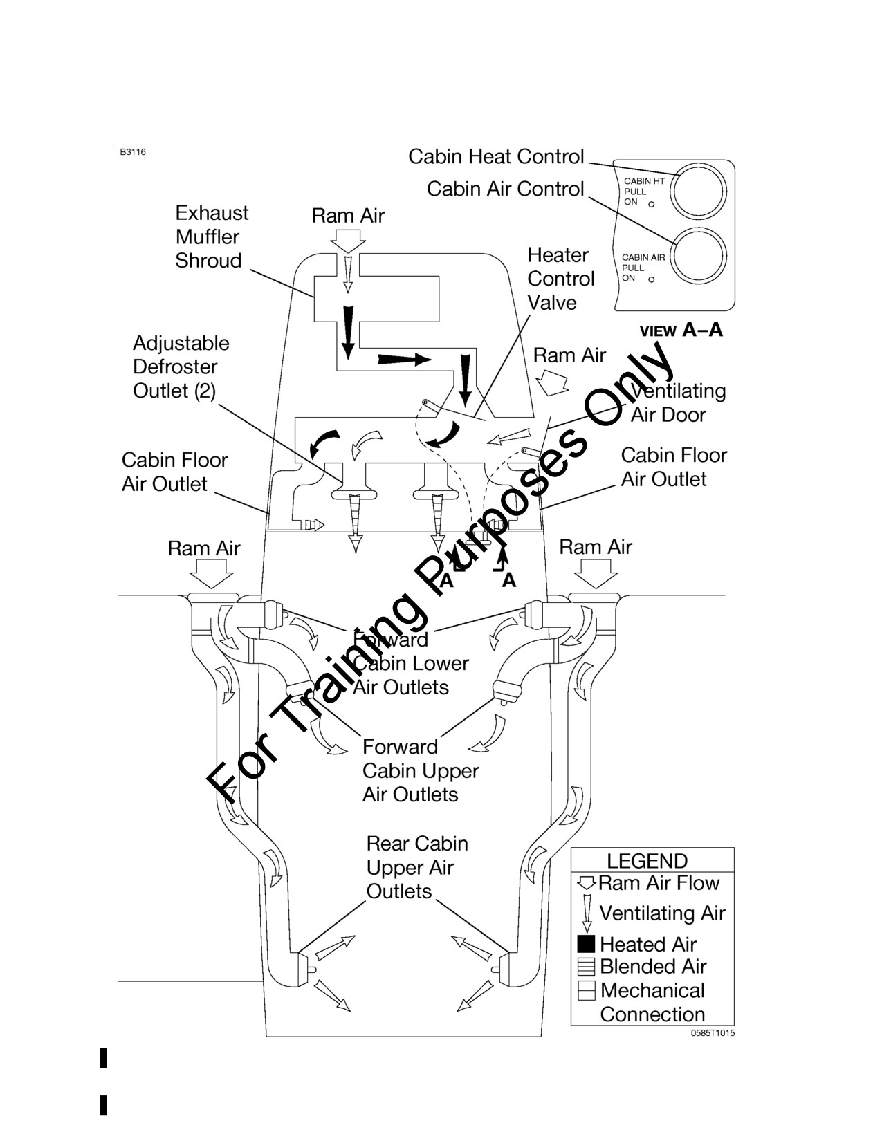
CESSNA
SECTION 7
MODEL 172S NAV III
AIRPLANE AND SYSTEM DESCRIPTION
KAP 140 AUTOPILOT
CABIN HEATING, VENTILATION AND DEFROSTING SYSTEM
Figure 7-8*
172SPHAUS-05
U.S.
7-63
SECTION 7
CESSNA
AIRPLANE AND SYSTEM DESCRIPTION
MODEL 172S NAV III
KAP 140 AUTOPILOT
PITOT-STATIC SYSTEM AND INSTRUMENTS
The pitot-static system uses a heated total pressure
(pitot) head
mounted on the lower surface of the left wing, external static port
mounted on the left side of the forward fuselage and associated
plumbing to connect the air data computer and the conventional pitot-
static instruments to the sources.
The heated pitot system uses an electrical heating element built in the
body of the pitot head. The PITOT HEAT control switch is found on the
switch panel below the lower left corner of the PFD. The PITOT HEAT
circuit breaker is found on the circuit breaker panel at the lower left side
of the pilot panel.
A static pressure alternate source valve (ALT STATIC AIR) is located
adjacent to the throttle control. The ALT STATIC AIR valve provides
static pressure from inside the cabin if the external static pressure
source becomes blocked.
If erroneous instrument readings are suspected due to water or ice in
the pressure line going to the standard external static pressure source,
the alternate static source valve should be pulled on.
Pressures within the cabin will vary with open heaters/vents and
windows. Refer to Section 5, Figure 5-1 (Sheet 2), for the Airspeed
Calibration, Alternate Static Source correction chart.
7-64
U.S.
172SPHAUS-05
CESSNA
SECTION 7
MODEL 172S NAV III
AIRPLANE AND SYSTEM DESCRIPTION
KAP 140 AUTOPILOT
VACUUM SYSTEM AND INSTRUMENTS
The vacuum system, refer to Figure
7-9, provides the vacuum
necessary to operate the standby attitude indicator. The system
consists of one engine-driven vacuum pump, a vacuum regulator, the
standby attitude indicator, a vacuum system air filter, and a vacuum
transducer. The vacuum transducer provides a signal to the engine
display that is processed and displayed as vacuum on the EIS ENGINE
page. If available vacuum, from the engine-driven vacuum pump, drops
below 3.5 in.hg., the LOW VACUUM annunciator will display in amber
on the PFD.
ATTITUDE INDICATOR
The standby attitude indicator is a vacuum-powered gyroscopic
instrument, found on the center instrument panel below the MFD. The
attitude indicator includes a low-vacuum warning flag (GYRO) that
comes into view when the vacuum is below the level necessary for
reliable gyroscope operation.
VACUUM INDICATOR
The vacuum indicator is incorporated on the EIS ENGINE page, found
along the left side of the PFD during engine start or the left edge of the
MFD during normal operation. During reversionary operation, the EIS
bar appears along the left side of the operational display.
LOW VACUUM ANNUNCIATION
A low vacuum condition is annunciated along the right side of the PFD
by a amber LOW VACUUM annunciator.
172SPHAUS-05
U.S.
7-65

SECTION 7
CESSNA
AIRPLANE AND SYSTEM DESCRIPTION
MODEL 172S NAV III
KAP 140 AUTOPILOT
VACUUM SYSTEM
Figure 7-9*
7-66
U.S.
172SPHAUS-05
CESSNA
SECTION 7
MODEL 172S NAV III
AIRPLANE AND SYSTEM DESCRIPTION
KAP 140 AUTOPILOT
CLOCK/O.A.T. INDICATOR
A numerical time or clock window, based on GPS time, and an outside
air temperature (O.A.T.) indicator window are provided along the lower
edge of the PFD. The O.A.T. indicator uses an air temperature sensor
located on top of the cabin.
STALL WARNING SYSTEM
The airplane is equipped with a pneumatic-type stall warning system
consisting of an inlet in the leading edge of the left wing, an air-
operated horn near the upper left corner of the windshield, and
associated plumbing. As the airplane approaches a stall, the low
pressure on the upper surface of the wings moves forward around the
leading edge of the wings. This low pressure creates a differential
pressure in the stall warning system which draws air through the
warning horn, resulting in a audible warning at 5 to 10 knots above stall
in all flight conditions.
The stall warning system should be checked during the preflight
inspection by applying suction to the system either by placing a clean
handkerchief over the vent opening and applying suction or using some
other type of suction device to activate the warning horn. The system is
operational if the warning horn sounds when suction is applied.
172SPHAUS-05
U.S.
7-67
SECTION 7
CESSNA
AIRPLANE AND SYSTEM DESCRIPTION
MODEL 172S NAV III
KAP 140 AUTOPILOT
STANDARD AVIONICS
The Garmin G1000 Avionics System is an integrated flight control and
navigation system. The system combines primary flight instruments,
communications, airplane system information and navigational
information all displayed on two color displays. The G1000 system
consists of the following pieces of equipment:
GARMIN DISPLAY UNITS (GDU)
Two identical units are mounted on the instrument panel. One, located
in front of the pilot, is configured as a PFD. A second panel, located to
the right, is configured as a MFD.
The PFD displays roll and pitch information, heading and course
navigation information, plus altitude, airspeed and vertical speed
information to the pilot. The PFD also controls and displays all
communication and navigation frequencies as well as displaying
warning/status annunciations of airplane systems.
The MFD displays a large scalable, moving map that corresponds to
the airplane's current location. Data from other components of the
system can be overlaid on this map. Location and direction of
movement of nearby aircraft, lightning and weather information can all
be displayed on the MFD. The MFD is also the principle display for all
of the engine, fuel, and electrical system parameters.
The reversionary mode places the flight information and basic engine
information on both the PFD and the MFD. This feature allows the pilot
full access to all necessary information should either of the display
screens malfunction.
(Continued Next Page)
7-68
U.S.
172SPHAUS-05
CESSNA
SECTION 7
MODEL 172S NAV III
AIRPLANE AND SYSTEM DESCRIPTION
KAP 140 AUTOPILOT
STANDARD AVIONICS (Continued)
AUDIO PANEL (GMA)
The audio panel for the G1000 system integrates all of the
communication and navigation digital audio signals, intercom system
and marker beacon controls in one unit. It is installed on the instrument
panel between the PFD and the MFD. The audio panel also controls
the reversionary mode for the PFD and MFD.
NOTE
Use of the COM 1/2 function is not approved.
INTEGRATED AVIONICS UNIT (GIA)
Two integrated avionics units are installed in the G1000 system. They
are mounted in racks in the tailcone, behind the baggage curtain.
These units act as the main communications hub linking all of the other
peripheral parts to the GDU displays. Each unit contains a GPS
receiver, a VHF navigation receiver, VHF communication transceiver
and the main system microprocessors. The first GIA unit to acquire a
GPS satellite 3-D navigation signal is the active GPS source.
ATTITUDE AND HEADING REFERENCE SYSTEM (AHRS)
AND MAGNETOMETER (GRS)
The AHRS provides airplane attitude and flight characteristics
information to the G1000 displays and to the integrated avionics units,
which is located in the tailcone of the airplane. The AHRS unit contains
accelerometers, tilt sensors and rate sensors that replace spinning
mass gyros used in other airplanes. The magnetometer is located
inside the left wing panel and interfaces with the AHRS to provide
heading information.
(Continued Next Page)
172SPHAUS-05
U.S.
7-69
SECTION 7
CESSNA
AIRPLANE AND SYSTEM DESCRIPTION
MODEL 172S NAV III
KAP 140 AUTOPILOT
STANDARD AVIONICS (Continued)
AIR DATA COMPUTER (GDC)
The Air Data Computer (ADC) compiles information from the airplane's
pitot-static system. The ADC unit is mounted behind the instrument
panel, just forward of the MFD. An outside air temperature probe,
mounted on top of the cabin, is connected to the ADC. The ADC
calculates pressure altitude, airspeed, true airspeed, vertical speed and
outside air temperature.
ENGINE MONITOR (GEA)
The Engine Monitor is responsible for receiving and processing the
signals from all of the engine and airframe sensors. It is connected to
all of the CHT measuring sensors, EGT sensors, RPM, fuel flow and to
the fuel gauging system. This unit transmits this information to the
engine display computers.
TRANSPONDER (GTX)
The full-featured Mode S transponder provides Mode A, C and S
functions. Control and operation of the transponder is accomplished
using the PFD. The transponder unit is mounted in the tailcone avionics
racks.
(Continued Next Page)
7-70
U.S.
172SPHAUS-05
CESSNA
SECTION 7
MODEL 172S NAV III
AIRPLANE AND SYSTEM DESCRIPTION
KAP 140 AUTOPILOT
STANDARD AVIONICS (Continued)
BENDIX/KING KAP 140 2 AXIS AUTOPILOT (if installed)
Refer to Section 9, Supplements 3, for operating information.
WARNING
WHEN THE KAP 140 AUTOPILOT IS ENGAGED IN NAV,
APR OR REV OPERATING MODES, IF THE HSI
NAVIGATION SOURCE IS CHANGED FROM GPS TO
NAV1 AUTOMATICALLY OR MANUALLY (USING THE
CDI SOFTKEY) OR MANUALLY FROM NAV2 TO GPS,
THE CHANGE WILL INTERRUPT THE NAVIGATION
SIGNAL TO THE AUTOPILOT AND WILL CAUSE THE
AUTOPILOT TO REVERT TO ROL MODE OPERATION.
NO WARNING CHIME OR PFD ANNUNCIATION IS
PROVIDED. THE PREVIOUSLY SELECTED MODE
SYMBOL SHOWN ON THE AUTOPILOT DISPLAY WILL
BE FLASHING TO SHOW THE REVERSION TO ROL
MODE OPERATION. IN ROL MODE, THE AUTOPILOT
WILL ONLY KEEP THE WINGS LEVEL AND WILL NOT
CORRECT THE AIRPLANE HEADING OR COURSE. SET
THE HDG BUG TO THE CORRECT HEADING AND
SELECT THE CORRECT NAVIGATION SOURCE ON
THE HSI USING THE CDI SOFTKEY BEFORE
ENGAGING THE AUTOPILOT IN ANY OTHER
OPERATING MODE.
XM WEATHER AND RADIO DATA LINK (GDL) (if installed)
The XM weather and radio data link provides weather information and
digital audio entertainment in the cockpit. The unit is mounted in the
tailcone, behind the baggage curtain. This unit communicates with the
MFD on the high-speed data bus. XM weather and XM radio operate in
the S-band frequency range to provide continuous uplink capabilities at
any altitude throughout North America. A subscription to the XM
satellite radio service is required for the XM weather and radio data link
to be used.
(Continued Next Page)
172SPHAUS-05
U.S.
7-71
SECTION 7
CESSNA
AIRPLANE AND SYSTEM DESCRIPTION
MODEL 172S NAV III
KAP 140 AUTOPILOT
AVIONICS SUPPORT EQUIPMENT
Avionics cooling fans, antennas, microphone and headset provisions,
power converter and static discharge wicks support the operation of the
avionics equipment installations.
AVIONICS COOLING FANS
Four DC electric fans provide forced air and ambient air circulation
cooling for the G1000 avionics equipment. A single fan in the tailcone
provides forced air cooling to the integrated avionics units and to the
transponder. A fan located forward of the instrument panel removes air
from between the firewall bulkhead and instrument panel, directing the
warm air up at the inside of the windshield. Two additional fans blow air
directly onto the heat sinks located on the forward sides of the PFD and
MFD.
Power is provided to these fans when the MASTER (BAT) switch and
the AVIONICS (BUS 1 and BUS 2) switch are all ON.
NOTE
None of the cooling fans will operate when the essential
bus avionics equipment is being powered by the standby
battery.
(Continued Next Page)
7-72
U.S.
172SPHAUS-05
CESSNA
SECTION 7
MODEL 172S NAV III
AIRPLANE AND SYSTEM DESCRIPTION
KAP 140 AUTOPILOT
AVIONICS SUPPORT EQUIPMENT (Continued)
ANTENNAS
Two combination VHF COM/GPS antennas are mounted on the top of
the cabin. The dual-mode COM 1/GPS 1 antenna is mounted on the
right side and the tri-mode COM 2/GPS 2/GDL antenna is mounted on
the left side. They are connected to the two VHF communication
transceivers, the two GPS receivers in the integrated avionics units,
and the GDL.
A blade-type navigation antenna is mounted on either side of the
vertical stabilizer. This antenna provides VOR and glideslope signals to
the VHF navigation receivers contained in the integrated avionics units.
The marker beacon antenna is mounted on the bottom of the tailcone.
It provides the signal to the marker beacon receiver located in the audio
panel.
The transponder antenna is mounted on the bottom of the cabin and is
connected to the Mode S transponder by a coaxial transmission cable.
The Bendix/King Distance Measuring Equipment (DME) antenna (if
installed) is mounted on the bottom of the tailcone and is connected to
the Bendix/King DME receiver by a coaxial cable.
(Continued Next Page)
172SPHAUS-05
U.S.
7-73
SECTION 7
CESSNA
AIRPLANE AND SYSTEM DESCRIPTION
MODEL 172S NAV III
KAP 140 AUTOPILOT
AVIONICS SUPPORT EQUIPMENT (Continued)
MICROPHONE AND HEADSET INSTALLATIONS
Standard equipment for the airplane includes a hand-held microphone,
an overhead speaker, two remote-keyed microphone switches on the
control wheels, and provisions for communications headsets at each
pilot and passenger station.
The hand-held microphone includes an integral push-to-talk switch.
This microphone is plugged in at the center pedestal and is accessible
to both the pilot and front passenger. Pressing the push-to-talk switch
allows voice transmission on the COM radios.
The overhead speaker is located in the center overhead console.
Volume and output for this speaker are controlled through the audio
panel.
Each control wheel contains a push-to-talk switch. This switch allows
the pilot or front passenger to transmit on the COM radios using remote
microphones.
Each seat position of the airplane has provisions for aviation-style
headsets. Microphone and headphone jacks are located on each
respective sidewall panel for communications between passengers and
pilot. The system is designed so that microphones are voice activated.
Only the pilot or front passenger can transmit through the COM radios.
NOTE
To ensure audibility and clarity when transmitting with the
hand-held microphone, always hold it as closely as possible
to the lips, then press the transmit switch and speak directly
into it. Avoid covering the opening on the back side of
microphone for optimum noise canceling.
(Continued Next Page)
7-74
U.S.
172SPHAUS-05
CESSNA
SECTION 7
MODEL 172S NAV III
AIRPLANE AND SYSTEM DESCRIPTION
KAP 140 AUTOPILOT
AVIONICS SUPPORT EQUIPMENT (Continued)
AUXILIARY AUDIO INPUT JACK
An auxiliary audio input jack (AUX AUDIO IN) is located on the center
pedestal, refer to Figure 7-2. It allows entertainment audio devices such
as cassette, compact disc, and MP3 players to play music over the
airplane's headsets.
The signal from AUX AUDIO IN is automatically muted during radio
communications or pilot selection of crew intercom isolation modes
located on the audio panel. The AUX key on the audio panel does not
control the AUX AUDIO IN signal. For a more complete description and
operating instructions of the audio panel, refer to the Garmin G1000
CRG.
Since the entertainment audio input is not controlled by a switch, there
is no way to deselect the entertainment source except to disconnect the
source at the audio input connector. In the event of a high pilot
workload and/or heavy traffic, it is wise to disable the entertainment
audio to eliminate a source of distraction for the flight crew.
NOTE
• Passenger briefing should specify that AUX AUDIO IN
(entertainment audio input) and Portable Electronic
Device (PED) use is permitted only during the enroute
phase of flight.
• Disconnect the cable from the AUX AUDIO IN jack when
not in use.
• Use caution with audio cables in the cabin to avoid
entangling occupants or cabin furnishings and to prevent
damage to cables.
(Continued Next Page)
172SPHAUS-05
U.S.
7-75
SECTION 7
CESSNA
AIRPLANE AND SYSTEM DESCRIPTION
MODEL 172S NAV III
KAP 140 AUTOPILOT
AVIONICS SUPPORT EQUIPMENT (Continued)
12V POWER OUTLET
A power converter, located on the cabin side of the firewall just forward
of the right instrument panel, reduces the airplane's 28 VDC power to
12 VDC. This converter provides up to 10 amps of power to operate
portable devices such as notebook computers and audio players. The
power output connector (POWER OUTLET 12V -10A) is located on the
center pedestal, refer to Figure 7-2.
For airplanes serials 172S10103 thru 172S10467 and 172S10469 thru
172S10506 and 172S10508 thru 172S10639 and 172S10641 thru
172S10655, a switch located on the switch panel labeled CABIN PWR
12V controls the operation of the power outlet.
CAUTION
• CHARGING OF LITHIUM BATTERIES MAY CAUSE
THE LITHIUM BATTERIES TO EXPLODE.
• TAKE CARE TO OBSERVE THE MANUFACTURER'S
POWER REQUIREMENTS PRIOR TO PLUGGING
ANY DEVICE INTO THE 12 VOLT CABIN POWER
SYSTEM CONNECTOR. THIS SYSTEM IS LIMITED TO
A MAXIMUM OF 10 AMPS.
• USE CAUTION WITH POWER/ADAPTER CABLES IN
THE CABIN TO AVOID ENTANGLING OCCUPANTS
OR CABIN FURNISHINGS AND TO PREVENT
DAMAGE TO CABLES SUPPLYING LIVE ELECTRIC
CURRENT.
• DISCONNECT POWER/ADAPTER CABLES WHEN
NOT IN USE.
(Continued Next Page)
7-76
U.S.
172SPHAUS-05
CESSNA
SECTION 7
MODEL 172S NAV III
AIRPLANE AND SYSTEM DESCRIPTION
KAP 140 AUTOPILOT
AVIONICS SUPPORT EQUIPMENT (Continued)
STATIC DISCHARGERS
Static dischargers are installed at various points throughout the
airframe to reduce interference from precipitation static. Under some
severe static conditions, loss of radio signals is possible even with
static dischargers installed. Whenever possible, avoid known severe
precipitation areas to prevent loss of dependable radio signals. If
avoidance is impractical, minimize airspeed and anticipate temporary
loss of radio signals while in these areas.
Static dischargers lose their effectiveness with age, and therefore,
should be checked periodically, at least at every annual inspection, by a
qualified technician.
172SPHAUS-05
U.S.
7-77
SECTION 7
CESSNA
AIRPLANE AND SYSTEM DESCRIPTION
MODEL 172S NAV III
KAP 140 AUTOPILOT
CABIN FEATURES
EMERGENCY LOCATOR TRANSMITTER (ELT)
Refer to Section
9, Supplements
1,
6, or
9 for appropriate ELT
operating information.
CABIN FIRE EXTINGUISHER
A portable Halon 1211 (Bromochlorodifluoromethane) fire extinguisher
is installed in a holder on the floorboard between the front seats to be
accessible in case of fire. The extinguisher is classified
5B:C by
Underwriters Laboratories.
The extinguisher should be checked prior to each flight to ensure that
the pressure of the contents, as indicated by the gage at the top of the
extinguisher, is within the green arc (approximately 125 psi) and the
operating lever lock pin is securely in place.
To operate the fire extinguisher:
1. Loosen retaining clamp(s) and remove extinguisher from bracket.
2. Hold extinguisher upright, pull operating ring pin, and press lever
while directing the liquid at the base of the fire at the near edge.
Progress toward the back of the fire by moving the nozzle rapidly
with a side-to-side sweeping motion.
WARNING
VENTILATE THE CABIN PROMPTLY AFTER
SUCCESSFULLY EXTINGUISHING THE FIRE TO
REDUCE THE GASES PRODUCED BY THERMAL
DECOMPOSITION.
3. The contents of the cabin fire extinguisher will empty in
approximately eight seconds of continuous use.
Fire extinguishers should be recharged by a qualified fire extinguisher
agency after each use. After recharging, secure the extinguisher to its
mounting bracket.
(Continued Next Page)
7-78
U.S.
172SPHAUS-05
CESSNA
SECTION 7
MODEL 172S NAV III
AIRPLANE AND SYSTEM DESCRIPTION
KAP 140 AUTOPILOT
CABIN FEATURES (Continued)
CARBON MONOXIDE DETECTION SYSTEM (if installed)
The carbon monoxide (CO) detection system consist of a single
detector located behind the instrument panel, powered by the
airplane’s DC electrical system and integrated in the Garmin G1000
system with a warning annunciation and alert messages displayed on
the PFD.
When the CO detection system senses a CO level of 50 parts-per-
million
(PPM) by volume or greater the alarm turns on a flashing
warning annunciation, CO LVL HIGH, in the annunciation window on
the PFD with a continuous tone until the PFD softkey below WARNING
is pushed. It then remains on steady until the CO level drops below 50
PPM and automatically resets the alarm.
If the CO system detects a problem within the system that requires
service, a CO DET SRVC message is displayed in the alerts window of
the PFD. If there is an interface problem between the G1000 system
and the CO system a CO DET FAIL message is displayed in the alerts
window of the PFD.
172SPHAUS-05
U.S.
7-79/7-80
CESSNA
SECTION 8
MODEL 172S NAV III
AIRPLANE HANDLING, SERVICE
KAP 140 AUTOPILOT
AND MAINTENANCE
AIRPLANE HANDLING, SERVICE
AND MAINTENANCE
TABLE OF CONTENTS
Page
Introduction
8-3
Identification Plate
8-3
Cessna Owner Advisories
8-4
United States Airplane Owners
8-4
International Airplane Owners
8-4
Publications
8-5
Airplane File
8-6
Airplane Inspection Periods
8-7
FAA Required Inspections
8-7
Cessna Inspection Programs
8-7
Cessna Customer Care Program
8-8
Pilot Conducted Preventive Maintenance
8-8
Alterations Or Repairs
8-9
Ground Handling
8-9
Towing
8-9
Parking
8-9
Tiedown
8-10
Jacking
8-10
Leveling
8-11
Flyable Storage
8-11
Servicing
8-12
Oil
8-13
Oil Specification
8-13
Recommended Viscosity For Temperature Range
8-13
Capacity Of Engine Sump
8-14
Oil And Oil Filter Change
8-14
(Continued Next Page)
172SPHAUS-05
U.S.
8-1
SECTION 8
CESSNA
AIRPLANE HANDLING, SERVICE
MODEL 172S NAV III
AND MAINTENANCE
KAP 140 AUTOPILOT
TABLE OF CONTENTS (Continued)
Page
Fuel
8-15
Approved Fuel Grades (And Colors)
8-15
Fuel Capacity
8-15
Fuel Additives
8-16
Fuel Contamination
8-20
Landing Gear
8-21
Cleaning And Care
8-22
Windshield And Windows
8-22
Painted Surfaces
8-23
Propeller Care
8-24
Engine Care
8-24
Interior Care
8-25/8-26
Avionics Care
8-25/8-26
8-2
U.S.
172SPHAUS-05
CESSNA
SECTION 8
MODEL 172S NAV III
AIRPLANE HANDLING, SERVICE
KAP 140 AUTOPILOT
AND MAINTENANCE
INTRODUCTION
This section contains factory recommended procedures for proper
ground handling and routine care and servicing of your airplane. It also
identifies certain inspection and maintenance requirements which must
be followed if your airplane is to retain that new airplane performance
and dependability. It is important to follow a planned schedule of
lubrication and preventive maintenance based on climatic and flying
conditions encountered in your local area.
Keep in touch with your local Cessna Authorized Service Facility and
take advantage of their knowledge and experience. Your Cessna
Authorized Service Facility knows your airplane and how to maintain it,
and will remind you when lubrications and oil changes are necessary,
as well as other seasonal and periodic services.
The airplane should be regularly inspected and maintained in
accordance with information found in the airplane maintenance manual
and in company issued service bulletins and service letters. All service
bulletins pertaining to the airplane by serial number should be
accomplished and the airplane should receive repetitive and required
inspections. Cessna does not condone modifications, whether by
Supplemental Type Certificate
(STC) or otherwise, unless these
certificates are held and/or approved by Cessna. Other modifications
may void warranties on the airplane since Cessna has no way of
knowing the full effect on the overall airplane. Operation of an airplane
that has been modified may be a risk to the occupants, and operating
procedures and performance data set forth in the POH may no longer
be considered accurate for the modified airplane.
IDENTIFICATION PLATE
All correspondence regarding your airplane should include the Serial
Number. The Serial Number, Model Number, Production Certificate
Number (PC) and Type Certificate Number (TC) can be found on the
Identification Plate, located on the aft left tailcone. The Finish and Trim
Plate, which is installed on the lower part of the left forward doorpost,
contains a code describing the exterior paint combination of the
airplane. The code may be used in conjunction with an applicable
Illustrated Parts Catalog if finish and trim information is needed.
172SPHAUS-05
U.S.
8-3
SECTION 8
CESSNA
AIRPLANE HANDLING, SERVICE
MODEL 172S NAV III
AND MAINTENANCE
KAP 140 AUTOPILOT
CESSNA OWNER ADVISORIES
Cessna Owner Advisories are sent to Cessna Aircraft FAA Registered
owners of record at no charge to inform them about mandatory and/or
beneficial airplane service requirements and product changes. Copies
of the actual bulletins are available from Cessna Authorized Service
Facilities and Cessna Customer Care.
As a convenience, service documents are now available online to all
our customers through a simple, free-of-charge registration process. If
you would like to sign up, please visit the “Customer Support Login” link
at www.cessna.com to register.
UNITED STATES AIRPLANE OWNERS
If your airplane is registered in the U.S., appropriate Cessna Owner
Advisories will be mailed to you automatically according to the latest
airplane registration name and address which you have provided to the
FAA. Therefore, it is important that you provide correct and up to date
mailing information to the FAA.
If you require a duplicate Owner Advisory to be sent to an address
different from the FAA aircraft registration address, please complete
and return an Owner Advisory Application (otherwise no action is
required on your part).
INTERNATIONAL AIRPLANE OWNERS
To receive Cessna Owner Advisories, please complete and return an
Owner Advisory Application.
Receipt of a valid Owner Advisory Application will establish your
Cessna Owner Advisory service for one year, after which you will be
sent a renewal notice. It is important that you respond promptly to
update your address for this critical service.
8-4
U.S.
172SPHAUS-05
CESSNA
SECTION 8
MODEL 172S NAV III
AIRPLANE HANDLING, SERVICE
KAP 140 AUTOPILOT
AND MAINTENANCE
PUBLICATIONS
Various publications and flight operation aids are furnished in the
airplane when delivered from the factory. These items are listed below.
• Customer Care Program Handbook
• Pilot’s Operating Handbook and FAA Approved Airplane
Flight Manual
• Pilot’s Checklist
• Passenger Briefing Card
• Cessna Authorized Service Facility Directory
To obtain additional publications or owner advisory information, you
may contact Cessna Customer Care at (316) 517-5800, Fax (316) 517-
7271 or write to Cessna Aircraft Company, P.O. Box 7706, Attn. Dept.
569, Wichita, KS 67277.
The following additional publications, plus many other supplies that are
applicable to your airplane, are available from a Cessna Authorized
Service Facility.
• Information Manual
(contains Pilot’s Operating
Handbook Information)
• Maintenance Manual, Wiring Diagram Manual and
Illustrated Parts Catalog
Cessna Authorized Service Facilities have access to a Customer Care
Supplies and Publications Catalog covering all available items, many of
which the Authorized Service Facility keeps on hand. The Authorized
Service Facility can place an order for any item which is not in stock.
NOTE
A Pilot's Operating Handbook and FAA Approved Airplane
Flight Manual which is lost or destroyed may be replaced by
contacting a Cessna Customer Care.
172SPHAUS-05
U.S.
8-5
SECTION 8
CESSNA
AIRPLANE HANDLING, SERVICE
MODEL 172S NAV III
AND MAINTENANCE
KAP 140 AUTOPILOT
AIRPLANE FILE
There are miscellaneous data, information and licenses that are a part
of the airplane file. The following is a checklist for that file. In addition, a
periodic check should be made of the latest Federal Aviation
Regulations to ensure that all data requirements are met.
To be displayed in the airplane at all times:
1. Aircraft Airworthiness Certificate (FAA Form 8100-2)
2. Aircraft Registration Certificate (FAA Form 8050-3)
3. Aircraft Radio Station License, (if applicable)
To be carried in the airplane at all times:
1. Current Pilot's Operating Handbook and FAA Approved Airplane
Flight Manual
2. Garmin G1000 Cockpit Reference Guide (190-00384-00 Rev. B
or subsequent)
3. Weight and Balance, and associated papers (latest copy of the
Repair and Alteration Form, FAA Form 337, if applicable)
4. Equipment List
To be made available upon request:
1. Airplane Logbook
2. Engine Logbook
Most of the items listed are required by the United States Federal
Aviation Regulations. Since the regulations of other nations may
require other documents and data, owners of airplanes not registered in
the United States should check with their own aviation officials to
determine their individual requirements.
Cessna recommends that these items, plus the Pilot's Checklists,
Customer Care Program Handbook and Customer Care Card, be
carried in the airplane at all times.
8-6
U.S.
172SPHAUS-05
CESSNA
SECTION 8
MODEL 172S NAV III
AIRPLANE HANDLING, SERVICE
KAP 140 AUTOPILOT
AND MAINTENANCE
AIRPLANE INSPECTION PERIODS
FAA REQUIRED INSPECTIONS
As required by U.S. Federal Aviation Regulations, all civil aircraft of
U.S. registry must undergo a complete inspection (annual) each twelve
calendar months. In addition to the required annual inspection, aircraft
operated commercially (for hire) must have a complete inspection
every 100 hours of operation.
The FAA may require other inspections by the issuance of
Airworthiness Directives
(ADs) applicable to the airplane, engine,
propeller and components. It is the responsibility of the owner/operator
to ensure compliance with all applicable airworthiness directives, and
when the inspections are repetitive, to take appropriate steps to prevent
inadvertent noncompliance.
CESSNA INSPECTION PROGRAMS
In lieu of the 100 hour and annual inspection requirements, an airplane
may be inspected in accordance with a Progressive Care Inspection
Program or a PhaseCard Inspection Program. Both programs offer
systems which allow the work load to be divided into smaller operations
that can be accomplished in shorter time periods.
The Cessna Progressive Care Inspection Program allows an airplane
to be inspected and maintained in four operations. The four operations
are recycled each 200 hours and are recorded in a specially provided
Aircraft Inspection Log as each operation is conducted.
The PhaseCard Inspection Program offers a parallel system for high-
utilization flight operations (approximately 600 flight hours per year).
This system utilizes 50 hour intervals (Phase 1 and Phase 2) to inspect
high-usage systems and components. At 12 months or 600 flight hours,
whichever occurs first, the airplane undergoes a complete (Phase 3)
inspection.
Regardless of the inspection method selected, the owner should keep
in mind that 14 CFR 43 and 14 CFR 91 establishes the requirement
that properly certified agencies or personnel accomplish all required
FAA inspections and most of the manufacturer recommended
inspections.
(Continued Next Page)
172SPHAUS-05
U.S.
8-7
SECTION 8
CESSNA
AIRPLANE HANDLING, SERVICE
MODEL 172S NAV III
AND MAINTENANCE
KAP 140 AUTOPILOT
AIRPLANE INSPECTION PERIODS (Continued)
CESSNA CUSTOMER CARE PROGRAM
Specific benefits and provisions of the Cessna Warranty plus other
important benefits for you are contained in the Customer Care Program
Handbook supplied with the airplane. The Customer Care Program
Handbook should be thoroughly reviewed and kept in the airplane at all
times.
Contact a Cessna Authorized Service Facility either at 50 hours for
your first Progressive Care Operation, or at 100 hours for your first 100
hour inspection depending on the program chosen for the airplane.
These inspections can be performed by any Cessna Authorized
Service Facility.
PILOT CONDUCTED PREVENTIVE MAINTENANCE
A certified pilot who owns or operates an airplane not used as an air
carrier is authorized by 14 CFR 43 to perform limited maintenance on
his airplane. Refer to 14 CFR 43 for a list of the specific maintenance
operations which are allowed.
NOTE
Pilots operating airplanes of other than U.S. registry should
refer to the regulations of the country of certification for
information on preventive maintenance that may be
performed by pilots.
A Maintenance Manual must be obtained prior to performing any
preventive maintenance to ensure that proper procedures are followed.
A Cessna Authorized Service Facility should be contacted for further
information or for required maintenance which must be accomplished
by appropriately licensed personnel.
8-8
U.S.
172SPHAUS-05
CESSNA
SECTION 8
MODEL 172S NAV III
AIRPLANE HANDLING, SERVICE
KAP 140 AUTOPILOT
AND MAINTENANCE
ALTERATIONS OR REPAIRS
It is essential that the FAA be contacted prior to any alterations on the
airplane to ensure that airworthiness of the airplane is not violated.
Alterations or repairs to the airplane must be accomplished by licensed
personnel, utilizing only FAA Approved components and FAA Approved
data, such as Cessna Service Bulletins.
GROUND HANDLING
TOWING
The airplane is most easily and safely maneuvered by hand with the
tow bar attached to the nosewheel (the tow bar is stowed on the side of
the baggage area). When towing with a vehicle, do not exceed the
nose gear turning angle of 30° either side of center, or damage to the
nose landing gear will result.
CAUTION
REMOVE ANY INSTALLED RUDDER LOCK BEFORE
TOWING.
If the airplane is towed or pushed over a rough surface during
hangaring, watch that the normal cushioning action of the nose strut
does not cause excessive vertical movement of the tail and the
resulting contact with low hangar doors or structure. A flat nose tire or
deflated strut will also increase tail height.
PARKING
When parking the airplane, head into the wind and set the parking
brake. Do not set the parking brake during cold weather when
accumulated moisture may freeze the brakes, or when the brakes are
overheated. Install the control wheel lock and chock the wheels. In
severe weather and high wind conditions, tie the airplane down as
outlined in the following paragraph.
(Continued Next Page)
172SPHAUS-05
U.S.
8-9
SECTION 8
CESSNA
AIRPLANE HANDLING, SERVICE
MODEL 172S NAV III
AND MAINTENANCE
KAP 140 AUTOPILOT
GROUND HANDLING (Continued)
TIEDOWN
Proper tiedown procedure is the best precaution against damage to the
parked airplane by gusty or strong winds. To tiedown the airplane
securely, proceed as follows:
1. Set the parking brake and install the control wheel lock.
2. Install a surface control lock over the fin and rudder.
3. Tie sufficiently strong ropes or chains
(700 pounds tensile
strength) to the wing, tail and nose tiedown fittings and secure
each rope or chain to a ramp tiedown.
4. Install a pitot tube cover.
JACKING
When a requirement exists to jack the entire airplane off the ground, or
when wing jack points are used in the jacking operation, refer to the
Maintenance Manual for specific procedures and equipment required.
Individual main gear may be jacked by using the jack pad which is
incorporated in the main landing gear strut step bracket. When using
the individual gear strut jack pad, flexibility of the gear strut will cause
the main wheel to slide inboard as the wheel is raised, tilting the jack.
The jack must then be lowered for a second jacking operation. Do not
jack both main wheels simultaneously using the individual main gear
jack pads.
CAUTION
DO NOT APPLY PRESSURE ON THE ELEVATOR OR
HORIZONTAL STABILIZER SURFACES. WHEN
PUSHING ON THE TAILCONE, ALWAYS APPLY
PRESSURE AT A BULKHEAD TO AVOID BUCKLING THE
SKIN.
If nose gear maintenance is required, the nosewheel may be raised off
the ground by pressing down on a tailcone bulkhead, just forward of the
horizontal stabilizer, and allowing the tail to rest on the tail tiedown ring.
(Continued Next Page)
8-10
U.S.
172SPHAUS-05
CESSNA
SECTION 8
MODEL 172S NAV III
AIRPLANE HANDLING, SERVICE
KAP 140 AUTOPILOT
AND MAINTENANCE
GROUND HANDLING (Continued)
JACKING (Continued)
To assist in raising and holding the nosewheel off the ground, ground
anchors should be utilized at the tail tiedown point.
NOTE
Ensure that the nose will be held off the ground under all
conditions by means of suitable stands or supports under
weight supporting bulkheads near the nose of the airplane.
LEVELING
Longitudinal leveling of the airplane is accomplished by placing a level
on leveling screws located on the left side of the tailcone. Deflate the
nose tire and/or lower or raise the nose strut to properly center the
bubble in the level. Corresponding points on both upper door sills may
be used to level the airplane laterally.
FLYABLE STORAGE
Engines in airplanes that are flown every 30 days or less may not
achieve normal service life because of internal corrosion. Corrosion
occurs when moisture from the air and the products of combustion
combine to attack cylinder walls and bearing surfaces during periods
when the airplane is not flown.
The minimum recommended operating frequency for the engine is one
continuous flight hour (not counting taxi, takeoff and landing time) with
oil temperatures of 165°F to 200°F every 30 days or less (depending on
location and storage conditions). Airplanes operated close to oceans,
lakes, rivers and in humid regions are in greater need of engine
preservation than airplanes operated in arid regions. Appropriate
engine preservation procedures must be practiced by the owner or
operator of the airplane based on present environmental conditions and
the frequency of airplane activity.
NOTE
The engine manufacturer does not recommend pulling the
engine through by hand during storage periods.
(Continued Next Page)
172SPHAUS-05
U.S.
8-11
SECTION 8
CESSNA
AIRPLANE HANDLING, SERVICE
MODEL 172S NAV III
AND MAINTENANCE
KAP 140 AUTOPILOT
GROUND HANDLING (Continued)
FLYABLE STORAGE (Continued)
If the airplane is to remain inactive for more than 30 days, consult the
latest revision of Textron Lycoming Service Letter L180
It is recommended when storing the airplane for any period of time to
keep fuel tanks full to minimize condensation in tanks. Keep the battery
fully charged to prevent the electrolyte from freezing in cold weather.
Refer to the Maintenance Manual for proper airplane storage
procedures.
SERVICING
In addition to the Preflight Inspection covered in Section 4 of this POH,
complete servicing, inspection and test requirements for your airplane
are detailed in the Maintenance Manual. The Maintenance Manual
outlines all items which require attention at specific intervals plus those
items which require servicing, inspection, and/or testing at special
intervals.
Since Cessna Authorized Service Facilities have the training and
equipment necessary to conduct all service, inspection, and test
procedures in accordance with applicable maintenance manuals, it is
recommended that owner/operators contact the Cessna Authorized
Service Facility concerning these requirements and begin scheduling
the airplane for service at the recommended intervals.
Cessna Progressive Care ensures that these requirements are
accomplished at the required intervals to comply with the 100 hour or
annual inspection as previously covered.
Depending on various flight operations, your local Government Aviation
Agency may require additional service, inspections, or tests. For these
regulatory requirements, owner/operators should check with local
aviation officials where the airplane is being operated.
For quick and ready reference, quantities, materials and specifications
for frequently used service items are as follows.
8-12
U.S.
172SPHAUS-05
CESSNA
SECTION 8
MODEL 172S NAV III
AIRPLANE HANDLING, SERVICE
KAP 140 AUTOPILOT
AND MAINTENANCE
OIL
OIL SPECIFICATION
MIL-L-6082 or SAE J1966 Aviation Grade Straight Mineral Oil: Used
when the airplane was delivered from the factory and should be used to
replenish the supply during the first 25 hours. This oil should be drained
and the filter changed after the first 25 hours of operation. Refill the
engine with MIL-L-6082 or SAE J1966 Aviation Grade Straight Mineral
Oil and continue to use until a total of 50 hours has accumulated or oil
consumption has stabilized.
MIL-L-22851 or SAE J1899 Aviation Grade Ashless Dispersant Oil: Oil
conforming to Textron Lycoming Service Instruction No 1014, and all
revisions and supplements thereto, must be used after first 50 hours
or oil consumption has stabilized.
RECOMMENDED VISCOSITY FOR TEMPERATURE
RANGE
Multiviscosity or straight grade oil may be used throughout the year for
engine lubrication. Refer to the following table for temperature versus
viscosity ranges.
MIL-L-6082
MIL-L-22851
or SAE J1966
or SAE J1899
Straight Mineral Oil
Ashless Dispersant Oil
Temperature
SAE Grade
SAE Grade
Above 27°C (80°F)
60
60
Above 16°C (60°F)
50
40 or 50
-1°C (30°F) to 32°C (90°F)
40
40
-18°C (0°F) to 21°C (70°F)
30
30, 40 or 20W-40
Below -12°C (10°F)
20
30 or 20W-30
-18°C (0°F) to 32°C (90°F)
20W-50
20W-50 or 15W-50
All Temperatures
---
15W-50 or 20W-50
NOTE
When operating temperatures overlap, use the lighter
grade of oil.
(Continued Next Page)
172SPHAUS-05
U.S.
8-13
SECTION 8
CESSNA
AIRPLANE HANDLING, SERVICE
MODEL 172S NAV III
AND MAINTENANCE
KAP 140 AUTOPILOT
OIL (Continued)
CAPACITY OF ENGINE SUMP
The engine has a total capacity of 9 quarts, with the oil filter accounting
for approximately 1 quart of that total. The engine oil sump has a
capacity of 8 quarts. The engine must not be operated on less than 5
quarts (as measured by the dipstick). For extended flights, the engine
should be filled to capacity.
OIL AND OIL FILTER CHANGE
After the first 25 hours of operation, drain the engine oil sump and
replace the filter. Refill sump with straight mineral oil and use until a
total of 50 hours has accumulated or oil consumption has stabilized;
then change to ashless dispersant oil. Ashless dispersant oil (and oil
filter) should be changed at time intervals set forth by the engine
manufacturer.
NOTE
During the first 25 hour oil and filter change, a general
inspection of the overall engine compartment is required.
Items which are not normally checked during a preflight
inspection should be given special attention. Hoses, metal
lines and fittings should be inspected for signs of oil and
fuel leaks, and checked for abrasions, chafing, security,
proper routing and support, and evidence of deterioration.
Inspect the intake and exhaust systems for cracks,
evidence of leakage, and security of attachment. Engine
controls and linkages should be checked for freedom of
movement through their full range, security of attachment
and evidence of wear. Inspect wiring for security, chafing,
burning, defective insulation, loose or broken terminals,
heat deterioration, and corroded terminals. Check the
alternator belt in accordance with Maintenance Manual
instructions, and retighten if necessary. A periodic check of
these items during subsequent servicing operations is
recommended.
8-14
U.S.
172SPHAUS-05
CESSNA
SECTION 8
MODEL 172S NAV III
AIRPLANE HANDLING, SERVICE
KAP 140 AUTOPILOT
AND MAINTENANCE
FUEL
APPROVED FUEL GRADES (AND COLORS)
100LL Grade Aviation Fuel (Blue)
100
Grade Aviation Fuel (Green)
NOTE
Isopropyl alcohol or Diethylene Glycol Monomethyl Ether
(DiEGME) may be added to the fuel supply in quantities not
to exceed 1% (alcohol) or 0.15% (DiEGME) of total volume.
Refer to Fuel Additives in later paragraphs for additional
information.
FUEL CAPACITY
56.0 U.S. Gallons Total:
28.0 U.S. Gallons per tank.
NOTE
• To ensure maximum fuel capacity when refueling and
minimize crossfeeding, the fuel selector valve should be
placed in either the LEFT or RIGHT position and the
airplane parked in a wings level, normal ground attitude.
Refer to Figure 1-1 for a definition of normal ground
attitude.
• Service the fuel system after each flight, and keep fuel
tanks full to minimize condensation in the tanks.
(Continued Next Page)
172SPHAUS-05
U.S.
8-15