CESSNA 172S NAV III Skyhawk SP. Information Manual (2016) - page 2
SECTION 3
CESSNA
EMERGENCY PROCEDURES
MODEL 172S NAV III
KAP 140 AUTOPILOT
ROUGH ENGINE OPERATION OR LOSS OF POWER
(Continued)
LOW OIL PRESSURE
If the low oil pressure annunciator (OIL PRESS) comes on, check the
oil pressure indicator (OIL PRES on ENGINE page or OIL PSI on
SYSTEM page) to confirm low oil pressure condition. If oil temperature
(OIL TEMP on ENGINE page or OIL °F on SYSTEM page) remains
normal, it is possible that the oil pressure sending unit or relief valve is
malfunctioning. Land at the nearest airport to determine the source of
the problem.
If a total loss of oil pressure and a rise in oil temperature occur at about
the same time, it could mean that the engine is about to fail. Reduce
power immediately and select a field suitable for a forced landing. Use
only the minimum power necessary to reach the landing site.
3-34
U.S.
172SPHAUS-05
CESSNA
SECTION 3
MODEL 172S NAV III
EMERGENCY PROCEDURES
KAP 140 AUTOPILOT
ELECTRICAL POWER SUPPLY SYSTEM
MALFUNCTIONS
Malfunctions in the electrical power supply system can be detected
through regular monitoring of the main battery ammeter (M BATT
AMPS) and the main electrical bus voltmeter
(M BUS VOLTS);
however, the cause of these malfunctions is usually difficult to
determine. A broken alternator drive belt, too much wear on the
alternator brushes, or an error in wiring is most likely the cause of
alternator failures, although other factors could cause the problem. A
defective Alternator Control Unit (ACU) can also cause malfunctions.
Problems of this nature constitute an electrical emergency and should
be dealt with immediately. Electrical power malfunctions usually fall into
two categories: excessive rate of charge and insufficient rate of charge.
The following paragraphs describe the recommended remedy for each
situation.
EXCESSIVE RATE OF CHARGE
After engine starting and heavy electrical usage at low engine speeds
(such as extended taxiing), the battery condition will be low enough to
accept above normal charging during the initial part of a flight.
However, after thirty minutes of cruising flight, the main battery
ammeter (M BATT AMPS) should be indicating less than 5 amps of
charging (+) current. If the charging current remains above this value
on a long flight, the battery electrolyte could overheat and evaporate.
Electronic components in the electrical system can be adversely
affected by higher than normal voltage. The ACU includes an
overvoltage sensor circuit which will automatically disconnect the
alternator if the charge voltage increases to more than approximately
31.75 volts. If the overvoltage sensor circuit does not operate correctly,
as shown by voltage more than 31.75 volts on the main battery bus
voltmeter, the MASTER switch ALT section should be set to the OFF
position. Unnecessary electrical equipment should be de-energized
and the flight terminated as soon as practical.
172SPHAUS-05
U.S.
3-35
SECTION 3
CESSNA
EMERGENCY PROCEDURES
MODEL 172S NAV III
KAP 140 AUTOPILOT
ELECTRICAL POWER SUPPLY SYSTEM
MALFUNCTIONS (Continued)
INSUFFICIENT RATE OF CHARGE
When the overvoltage sensor circuit, or other fault, opens the alternator
(ALT FIELD) circuit breaker and de-energizes the alternator, a
discharge (-) current will be shown on the main battery ammeter and
the low voltage annunciator (LOW VOLTS) will come on. The ACU can
de-energize the alternator due to minor disturbances in the electrical
system, resulting in a nuisance opening of the ALT FIELD circuit
breaker. If this happens, an attempt should be made to energize the
alternator system.
To energize the alternator system
1. MASTER Switch (ALT Only) - OFF
2. ALT FIELD Circuit Breaker - CHECK IN
3. MASTER Switch (ALT Only) - ON
If the problem was a minor ACU disturbance in the electrical system,
normal main battery charging will start. A charge (+) current will be
shown on the main battery ammeter and the LOW VOLTS annunciator
will go off.
If the LOW VOLTS annunciator comes on again, there is an alternator
system problem. Do not repeat steps to energize the alternator system.
The electrical load on the battery must be minimized (by de-energizing
nonessential electrical equipment and avionics) because the battery
can supply the electrical system for only a short time. Reduce electrical
load as soon as possible to extend the life of the battery for landing.
Land as soon as practical.
(Continued Next Page)
3-36
U.S.
172SPHAUS-05
CESSNA
SECTION 3
MODEL 172S NAV III
EMERGENCY PROCEDURES
KAP 140 AUTOPILOT
ELECTRICAL POWER SUPPLY SYSTEM
MALFUNCTIONS (Continued)
INSUFFICIENT RATE OF CHARGE (Continued)
Main battery life can be extended by setting the MASTER switch (ALT
and BAT) to OFF and operating the equipment on the ESS BUS from
the standby battery. The standby battery is only capable of providing
power for systems on the essential bus and cannot provide power for
transponder (XPDR) operation. Main battery life should be extended,
when practical, for possible later operation of the wing flaps and use of
the landing light (at night).
NOTE
The LOW VOLTS annunciator can come on when the
engine is operated at low RPM with a high electrical load.
The LOW VOLTS annunciator will usually go off when the
engine is operated at higher RPM for greater alternator
system output. Make sure that the M BATT AMPS
indication shows positive (+) current at the higher RPM.
172SPHAUS-05
U.S.
3-37
SECTION 3
CESSNA
EMERGENCY PROCEDURES
MODEL 172S NAV III
KAP 140 AUTOPILOT
HIGH CARBON MONOXIDE (CO) LEVEL ADVISORY
(if installed)
Carbon monoxide (CO) is a colorless, odorless, tasteless product of an
internal combustion engine and is always present in exhaust fumes.
Even minute quantities of carbon monoxide breathed over a long
period of time may lead to dire consequences. The symptoms of
carbon monoxide poisoning are difficult to detect by the person affected
and may include blurred thinking, a feeling of uneasiness, dizziness,
headache, and loss of consciousness.
The cabin heater system operates by allowing ambient air to flow
through an exhaust shroud where it is heated before being ducted into
the cabin. If an exhaust leak, caused by a crack in the exhaust pipe,
occurs in the area surrounded by this shroud it would allow exhaust
fumes to mix with the heated ambient air being ducted into the cabin.
Therefore, if anyone in the cabin smells exhaust fumes, experiences
any of the symptoms mentioned above, or the CO LVL HIGH warning
annunciation comes on when using the cabin heater, immediately turn
off the cabin heater and preform the emergency items for High Carbon
Monoxide (CO) Level Advisory.
When the CO detection system senses a CO level of 50 parts per
million
(PPM) by volume or greater, the alarm turns on a flashing
warning annunciation CO LVL HIGH in the annunciation window on the
PFD with a continuous tone until the PFD softkey below WARNING is
pushed. It then remains on steady until the CO level drops below 50
PPM and automatically resets the alarm.
OTHER EMERGENCIES
WINDSHIELD DAMAGE
If a bird strike or other incident should damage the windshield in flight to
the point of creating an opening, a significant loss in performance may
be expected. This loss may be minimized in some cases (depending on
amount of damage, altitude, etc.) by opening the side windows while
the airplane is maneuvered for a landing at the nearest airport. If
airplane performance or other adverse conditions prevent landing at an
airport, prepare for an off airport landing in accordance with the
Precautionary Landing With Engine Power or Ditching checklists.
3-38
U.S.
172SPHAUS-05
CESSNA
SECTION 4
MODEL 172S NAV III
NORMAL PROCEDURES
KAP 140 AUTOPILOT
NORMAL PROCEDURES
TABLE OF CONTENTS
Page
Introduction
4-3
Airspeeds For Normal Operation
4-3
NORMAL PROCEDURES
4-4
Preflight Inspection
4-4
Cabin
4-5
Empennage
4-6
Right Wing Trailing Edge
4-6
Right Wing
4-7
Nose
4-8
Left Wing
4-9
Left Wing Leading Edge
4-10
Left Wing Trailing Edge
4-10
Before Starting Engine
4-11
Starting Engine (With Battery)
4-12
Starting Engine (With External Power)
4-13
Before Takeoff
4-15
Takeoff
4-18
Normal Takeoff
4-18
Short Field Takeoff
4-18
Enroute Climb
4-19
Cruise
4-19
Descent
4-19
Before Landing
4-21
Landing
4-21
Normal Landing
4-21
Short Field Landing
4-21
Balked Landing
4-22
After Landing
4-22
Securing Airplane
4-22
(Continued Next Page)
172SPHAUS-05
U.S.
4-1
SECTION 4
CESSNA
NORMAL PROCEDURES
MODEL 172S NAV III
KAP 140 AUTOPILOT
TABLE OF CONTENTS (Continued)
Page
AMPLIFIED NORMAL PROCEDURES
4-23
Preflight Inspection
4-23
Starting Engine
4-25
Recommended Starter Duty Cycle
4-26
Leaning For Ground Operations
4-26
Fuel Vapor Procedures
4-27
Taxiing
4-28
Before Takeoff
4-30
Warm Up
4-30
Magneto Check
4-30
Alternator Check
4-30
Elevator Trim
4-31
Landing Lights
4-31
Takeoff
4-31
Power Check
4-31
Wing Flap Settings
4-32
Crosswind Takeoff
4-32
Enroute Climb
4-33
Cruise
4-34
Leaning Using Exhaust Gas Temperature (EGT)
4-36
Fuel Savings Procedures For Flight Training Operations
4-39
Stalls
4-40
Spins
4-40
Holding, Procedure Turns and Missed Approaches
4-43
Landing
4-47
Normal Landing
4-47
Short Field Landing
4-47
Crosswind Landing
4-48
Balked Landing
4-48
Cold Weather Operations
4-49
Starting
4-50
Winterization Kit
4-51
Hot Weather Operations
4-52
Noise Characteristics
4-52
4-2
U.S.
172SPHAUS-05
CESSNA
SECTION 4
MODEL 172S NAV III
NORMAL PROCEDURES
KAP 140 AUTOPILOT
INTRODUCTION
Section 4 provides procedures and amplified instructions for normal
operations using standard equipment. Normal procedures associated
with optional systems can be found in Section 9, Supplements.
AIRSPEEDS FOR NORMAL OPERATION
Unless otherwise noted, the following speeds are based on a maximum
weight of 2550 pounds and may be used for any lesser weight.
TAKEOFF
Normal Climb
75 - 85 KIAS
Short Field Takeoff, Flaps 10°, Speed at 50 Feet
56 KIAS
ENROUTE CLIMB, FLAPS UP
Normal, Sea Level
75 - 85 KIAS
Normal, 10,000 Feet
70 - 80 KIAS
Best Rate of Climb, Sea Level
74 KIAS
Best Rate of Climb, 10,000 Feet
72 KIAS
Best Angle of Climb, Sea Level
62 KIAS
Best Angle of Climb, 10,000 Feet
67 KIAS
LANDING APPROACH
Normal Approach, Flaps UP
65 - 75 KIAS
Normal Approach, Flaps FULL
60 - 70 KIAS
Short Field Approach, Flaps FULL
61 KIAS
BALKED LANDING
Maximum Power, Flaps 20°
60 KIAS
MAXIMUM RECOMMENDED TURBULENT AIR
PENETRATION SPEED
2550 POUNDS
105 KIAS
2200 POUNDS
98 KIAS
1900 POUNDS
90 KIAS
MAXIMUM DEMONSTRATED CROSSWIND VELOCITY
Takeoff, Flaps UP
20 KNOTS
Takeoff, Flaps 10°
20 KNOTS
Landing, Flaps 10°
20 KNOTS
Landing, Flaps FULL
15 KNOTS
172SPHAUS-05
U.S.
4-3
SECTION 4
CESSNA
NORMAL PROCEDURES
MODEL 172S NAV III
KAP 140 AUTOPILOT
NORMAL PROCEDURES
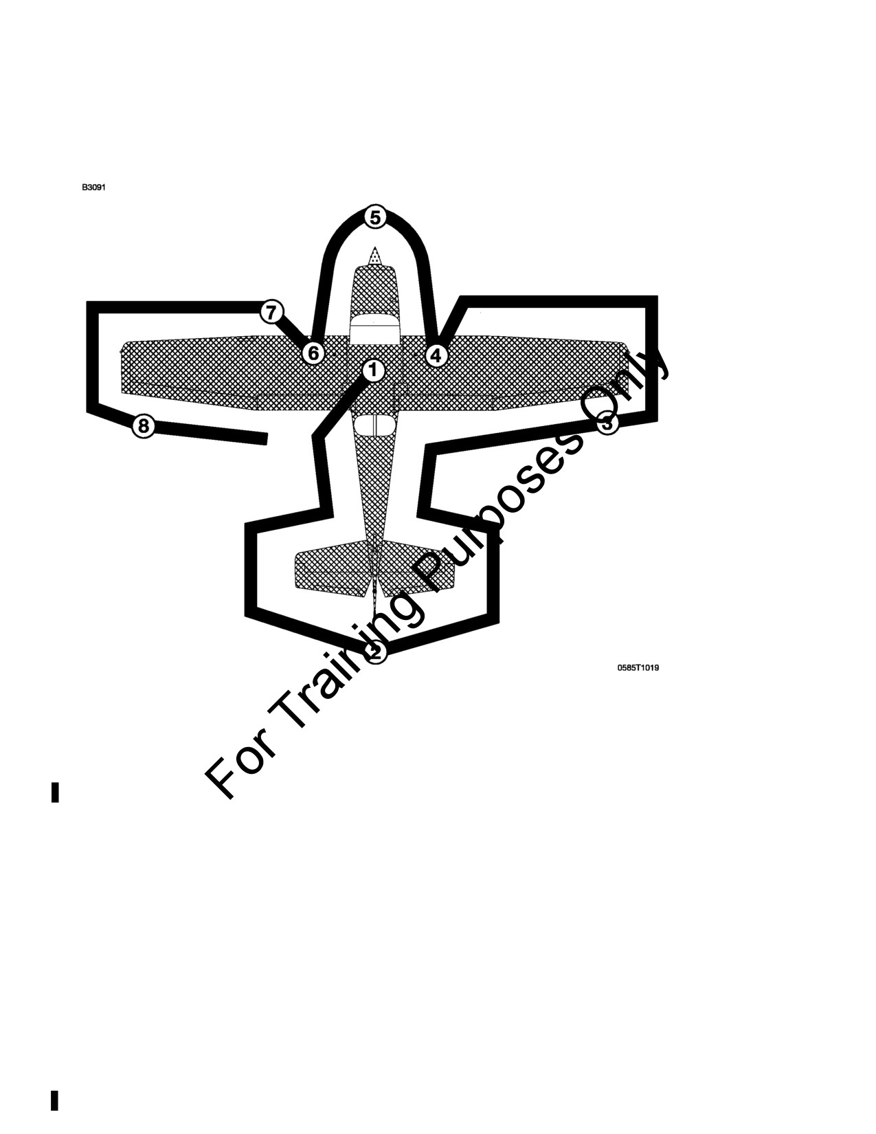
PREFLIGHT INSPECTION
NOTE
Visually check airplane for general condition during walk-
around inspection. Airplane should be parked in a normal
ground attitude, refer to Figure 1-1, to make sure that fuel
drain valves allow for accurate sampling. Use of the
refueling steps and assist handles will simplify access to
the upper wing surfaces for visual checks and refueling
operations. In cold weather, remove even small
accumulations of frost, ice or snow from wing, tail and
control surfaces. Also, make sure that control surfaces
contain no internal accumulations of ice or debris. Prior to
flight, check that pitot heater is warm to touch within 30
seconds with battery and pitot heat switches on. If a night
flight is planned, check operation of all lights, and make
sure a flashlight is available.
Figure 4-1
4-4
U.S.
172SPHAUS-05
CESSNA
SECTION 4
MODEL 172S NAV III
NORMAL PROCEDURES
KAP 140 AUTOPILOT
PREFLIGHT INSPECTION (Continued)
CABIN
1. Pitot Tube Cover - REMOVE (check for pitot blockage)
2. Pilot's Operating Handbook - ACCESSIBLE TO PILOT
3. Garmin G1000 Cockpit Reference Guide - ACCESSIBLE TO
PILOT
4. Airplane Weight and Balance - CHECKED
5. Parking Brake - SET
6. Control Wheel Lock - REMOVE
WARNING
WHEN THE MASTER SWITCH IS ON, USING AN
EXTERNAL POWER SOURCE, OR MANUALLY
ROTATING THE PROPELLER, TREAT THE PROPELLER
AS IF THE MAGNETOS SWITCH WERE ON. DO NOT
STAND, NOR ALLOW ANYONE ELSE TO STAND,
WITHIN THE ARC OF THE PROPELLER SINCE A
LOOSE OR BROKEN WIRE, OR A COMPONENT
MALFUNCTION, COULD CAUSE THE ENGINE TO
START.
7. MAGNETOS Switch - OFF
8. AVIONICS Switch (BUS 1 and BUS 2) - OFF
9. MASTER Switch (ALT and BAT) - ON
10. Primary Flight Display (PFD) - CHECK (verify PFD is ON)
11. FUEL QTY (L and R) - CHECK
12. LOW FUEL L and LOW FUEL R Annunciators - CHECK (verify
annunciators are not shown on PFD)
13. OIL PRESSURE Annunciator - CHECK (verify annunciator is
shown)
14. LOW VACUUM Annunciator - CHECK (verify annunciator is
shown)
15. AVIONICS Switch (BUS 1) - ON
16. Forward Avionics Fan - CHECK (verify fan is heard)
(Continued Next Page)
172SPHAUS-05
U.S.
4-5
SECTION 4
CESSNA
NORMAL PROCEDURES
MODEL 172S NAV III
KAP 140 AUTOPILOT
PREFLIGHT INSPECTION (Continued)
CABIN (Continued)
17. AVIONICS Switch (BUS 1) - OFF
18. AVIONICS Switch (BUS 2) - ON
19. Aft Avionics Fan - CHECK (verify fan is heard)
20. AVIONICS Switch (BUS 2) - OFF
21. PITOT HEAT Switch - ON (carefully check that pitot tube
is
warm to the touch within 30 seconds)
22. PITOT HEAT Switch - OFF
23. LOW VOLTS Annunciator
- CHECK
(verify annunciator
is
shown)
24. MASTER Switch (ALT and BAT) - OFF
25. Elevator Trim Control - TAKEOFF position
26. FUEL SELECTOR Valve - BOTH
27. ALT STATIC AIR Valve - OFF (push full in)
28. Fire Extinguisher - CHECK (verify gage pointer in green arc)
EMPENNAGE
1. Baggage Compartment Door - CHECK (lock with key)
2. Autopilot Static Source (if installed) - CHECK (verify opening is
clear)
3. Rudder Gust Lock (if installed) - REMOVE
4. Tail Tiedown - DISCONNECT
5. Control Surfaces - CHECK (freedom of movement and security)
6. Elevator Trim Tab - CHECK (security)
7. Antennas
- CHECK
(security of attachment and general
condition)
RIGHT WING Trailing Edge
1. Flap - CHECK (security and condition)
2. Aileron - CHECK (freedom of movement and security)
4-6
U.S.
172SPHAUS-05
CESSNA
SECTION 4
MODEL 172S NAV III
NORMAL PROCEDURES
KAP 140 AUTOPILOT
PREFLIGHT INSPECTION (Continued)
RIGHT WING
1. Wing Tiedown - DISCONNECT
2. Main Wheel Tire
- CHECK
(proper inflation and general
condition (weather checks, tread depth and wear, etc.))
3. Fuel Tank Sump Quick Drain Valves - DRAIN
Drain at least a cupful of fuel (using sampler cup) from each
sump location to check for water, sediment, and proper fuel
grade before each flight and after each refueling. If water is
observed, take further samples until clear and then gently rock
wings and lower tail to the ground to move any additional
contaminants to the sampling points. Take repeated samples
from all fuel drain points until all contamination has been
removed. If contaminants are still present, refer to WARNING
below and do not fly airplane.
NOTE
Collect all sampled fuel in a safe container. Dispose of the
sampled fuel so that it does not cause a nuisance, hazard
or damage to the environment.
WARNING
IF, AFTER REPEATED SAMPLING, EVIDENCE OF
CONTAMINATION STILL EXISTS, THE AIRPLANE
SHOULD NOT BE FLOWN. TANKS SHOULD BE
DRAINED AND SYSTEM PURGED BY QUALIFIED
MAINTENANCE PERSONNEL. ALL EVIDENCE OF
CONTAMINATION MUST BE REMOVED BEFORE
FURTHER FLIGHT.
4. Fuel Quantity - CHECK VISUALLY (for desired level)
5. Fuel Filler Cap - SECURE and VENT CLEAR
172SPHAUS-05
U.S.
4-7
SECTION 4
CESSNA
NORMAL PROCEDURES
MODEL 172S NAV III
KAP 140 AUTOPILOT
PREFLIGHT INSPECTION (Continued)
NOSE
1. Fuel Strainer Quick Drain Valve (located on bottom of fuselage) -
DRAIN
Drain at least a cupful of fuel (using sampler cup) from valve to
check for water, sediment, and proper fuel grade before each
flight and after each refueling. If water is observed, take further
samples until clear and then gently rock wings and lower tail to
the ground to move any additional contaminants to the sampling
points. Take repeated samples from all fuel drain points,
including the fuel reservoir and fuel selector, until all
contamination has been removed. If contaminants are still
present, refer to WARNING below and do not fly the airplane.
NOTE
Collect all sampled fuel in a safe container. Dispose of the
sampled fuel so that it does not cause a nuisance, hazard,
or damage to the environment.
WARNING
IF, AFTER REPEATED SAMPLING, EVIDENCE OF
CONTAMINATION STILL EXISTS, THE AIRPLANE
SHOULD NOT BE FLOWN. TANKS SHOULD BE
DRAINED AND SYSTEM PURGED BY QUALIFIED
MAINTENANCE PERSONNEL. ALL EVIDENCE OF
CONTAMINATION MUST BE REMOVED BEFORE
FURTHER FLIGHT.
2. Engine Oil Dipstick/Filler Cap:
a. Oil level - CHECK
b. Dipstick/Filler Cap - SECURE
NOTE
Do not operate with less than 5 quarts. Fill to 8 quarts for
extended flight.
3. Engine Cooling Air Inlets - CHECK (clear of obstructions)
4. Propeller and Spinner - CHECK (for nicks and security)
5. Air Filter
- CHECK (for restrictions by dust or other foreign
matter)
(Continued Next Page)
4-8
U.S.
172SPHAUS-05
CESSNA
SECTION 4
MODEL 172S NAV III
NORMAL PROCEDURES
KAP 140 AUTOPILOT
PREFLIGHT INSPECTION (Continued)
NOSE (Continued)
6. Nosewheel Strut and Tire - CHECK (proper inflation of strut and
general condition of tire (weather checks, tread depth and wear,
etc.))
7. Static Source Opening (left side of fuselage) - CHECK (verify
opening is clear)
LEFT WING
1. Fuel Quantity - CHECK VISUALLY (for desired level)
2. Fuel Filler Cap - SECURE and VENT CLEAR
3. Fuel Tank Sump Quick Drain Valves - DRAIN
Drain at least a cupful of fuel (using sampler cup) from each
sump location to check for water, sediment, and proper fuel
grade before each flight and after each refueling. If water is
observed, take further samples until clear and then gently rock
wings and lower tail to the ground to move any additional
contaminants to the sampling points. Take repeated samples
from all fuel drain points until all contamination has been
removed. If contaminants are still present, refer to WARNING
below and do not fly airplane.
NOTE
Collect all sampled fuel in a safe container. Dispose of the
sampled fuel so that it does not cause a nuisance, hazard,
or damage to the environment.
WARNING
IF, AFTER REPEATED SAMPLING, EVIDENCE OF
CONTAMINATION STILL EXISTS, THE AIRPLANE
SHOULD NOT BE FLOWN. TANKS SHOULD BE
DRAINED AND SYSTEM PURGED BY QUALIFIED
MAINTENANCE PERSONNEL. ALL EVIDENCE OF
CONTAMINATION MUST BE REMOVED BEFORE
FURTHER FLIGHT.
4. Main Wheel Tire
- CHECK
(proper inflation and general
condition (weather checks, tread depth and wear, etc.))
172SPHAUS-05
U.S.
4-9
SECTION 4
CESSNA
NORMAL PROCEDURES
MODEL 172S NAV III
KAP 140 AUTOPILOT
PREFLIGHT INSPECTION (Continued)
LEFT WING Leading Edge
1. Fuel Tank Vent Opening - CHECK (blockage)
2. Stall Warning Opening - CHECK (blockage)
NOTE
To check the system, place a clean handkerchief over the
vent opening and apply suction; a sound from the warning
horn will confirm system operation.
3. Wing Tiedown - DISCONNECT
4. Landing/Taxi Light(s) - CHECK (condition and cleanliness of
cover)
LEFT WING Trailing Edge
1. Aileron - CHECK (freedom of movement and security)
2. Flap - CHECK (security and condition)
4-10
U.S.
172SPHAUS-05
CESSNA
SECTION 4
MODEL 172S NAV III
NORMAL PROCEDURES
KAP 140 AUTOPILOT
BEFORE STARTING ENGINE
1. Preflight Inspection - COMPLETE
2. Passenger Briefing - COMPLETE
3. Seats and Seat Belts - ADJUST and LOCK (verify inertia reel
locking)
4. Brakes - TEST and SET
5. Circuit Breakers - CHECK IN
6. Electrical Equipment - OFF
7. AVIONICS Switch (BUS 1 and BUS 2) - OFF
CAUTION
THE AVIONICS SWITCH (BUS 1 AND BUS 2) MUST BE
OFF DURING ENGINE START TO PREVENT POSSIBLE
DAMAGE TO AVIONICS.
8. FUEL SELECTOR Valve - BOTH
9. FUEL SHUTOFF Valve - ON (push full in)
172SPHAUS-05
U.S.
4-11
SECTION 4
CESSNA
NORMAL PROCEDURES
MODEL 172S NAV III
KAP 140 AUTOPILOT
STARTING ENGINE (With Battery)
1. Throttle Control - OPEN 1/4 INCH
2. Mixture Control - IDLE CUTOFF (pull full out)
3. STBY BATT Switch:
a. TEST - (hold for 10 seconds, verify that green TEST lamp
does not go off)
b. ARM - (verify that PFD comes on)
4. Engine Indicating System - CHECK PARAMETERS (verify no
red X's through ENGINE page indicators)
5. BUS E Volts - CHECK (verify 24 VOLTS minimum shown)
6. M BUS Volts - CHECK (verify 1.5 VOLTS or less shown)
7. BATT S Amps - CHECK (verify discharge shown (negative))
8. STBY BATT Annunciator - CHECK (verify annunciator is shown)
9. Propeller Area - CLEAR (verify that all people and equipment
are at a safe distance from the propeller)
10. MASTER Switch (ALT and BAT) - ON
11. BEACON Light Switch - ON
NOTE
If engine is warm, omit priming procedure steps 12 thru 14
below.
12. FUEL PUMP Switch - ON
13. Mixture Control - SET to FULL RICH (full forward) until stable
fuel flow is indicated (approximately 3 to 5 seconds), then set to
IDLE CUTOFF (full aft) position.
14. FUEL PUMP Switch - OFF
15. MAGNETOS Switch - START (release when engine starts)
16. Mixture Control
- ADVANCE SMOOTHLY TO RICH (when
engine starts)
NOTE
If the engine is primed too much
(flooded), place the
mixture control in the IDLE CUTOFF position, open the
throttle control
1/2 to full, and engage the starter motor
(START). When the engine starts, advance the mixture
control to the FULL RICH position and retard the throttle
control promptly.
(Continued Next Page)
4-12
U.S.
172SPHAUS-05
CESSNA
SECTION 4
MODEL 172S NAV III
NORMAL PROCEDURES
KAP 140 AUTOPILOT
STARTING ENGINE (With Battery) (Continued)
17. Oil Pressure - CHECK (verify that oil pressure increases into the
GREEN BAND range in 30 to 60 seconds)
18. AMPS (M BATT and BATT S) - CHECK (verify charge shown
(positive))
19. LOW VOLTS Annunciator - CHECK (verify annunciator is not
shown)
20. NAV Light Switch - ON as required
21. AVIONICS Switch (BUS 1 and BUS 2) - ON
STARTING ENGINE (With External Power)
1.
Throttle Control - OPEN 1/4 INCH
2.
Mixture Control - IDLE CUTOFF (pull full out)
3.
STBY BATT Switch:
a. TEST - (hold for 10 seconds, verify green TEST lamp does
not go off)
b. ARM - (verify that PFD comes on)
4.
Engine Indication System - CHECK PARAMETERS (verify no
red X's through ENGINE page indicators)
5.
BUS E Volts - CHECK (verify 24 VOLTS minimum shown)
6.
M BUS Volts - CHECK (verify 1.5 VOLTS or less shown)
7.
BATT S Amps - CHECK (verify discharge shown (negative))
8.
STBY BATT Annunciator - CHECK (verify annunciator is shown)
9.
AVIONICS Switch (BUS 1 and BUS 2) - OFF
10. MASTER Switch (ALT and BAT) - OFF
11.
Propeller Area - CLEAR (verify that all people and equipment
are at a safe distance from the propeller)
12. External Power - CONNECT (to ground power receptacle)
13. MASTER Switch (ALT and BAT) - ON
14. BEACON Light Switch - ON
15. M BUS VOLTS - CHECK (verify that approximately 28 VOLTS is
shown)
NOTE
If engine is warm, omit priming procedure steps 16 thru 18.
16. FUEL PUMP Switch - ON
(Continued Next Page)
172SPHAUS-05
U.S.
4-13
SECTION 4
CESSNA
NORMAL PROCEDURES
MODEL 172S NAV III
KAP 140 AUTOPILOT
STARTING ENGINE (With External Power) (Continued)
17. Mixture Control - SET to FULL RICH (full forward) until stable
fuel flow is indicated (approximately 3 to 5 seconds), then set to
IDLE CUTOFF (full aft) position.
18. FUEL PUMP Switch - OFF
19. MAGNETOS Switch - START (release when engine starts)
20. Mixture Control
- ADVANCE SMOOTHLY TO RICH (when
engine starts)
NOTE
If the engine is primed too much
(flooded), place the
mixture control in the IDLE CUTOFF position, open the
throttle control
1/2 to full, and engage the starter motor
(START). When the engine starts, advance the mixture
control to the FULL RICH position and retard the throttle
control promptly.
21. Oil Pressure - CHECK (verify oil pressure increases into the
GREEN BAND range in 30 to 60 seconds)
22. Power - REDUCE TO IDLE
23. External Power
- DISCONNECT FROM GROUND POWER
(latch external power receptacle door)
24. Power - INCREASE (to approximately 1500 RPM for several
minutes to charge battery)
25. AMPS (M BATT and BATT S) - CHECK (verify charge shown
(positive))
26. LOW VOLTS Annunciator - CHECK (verify annunciator is not
shown)
27. Internal Power - CHECK
a. MASTER Switch (ALT) - OFF
b. TAXI and LAND Light Switches - ON
c. Throttle Control - REDUCE TO IDLE
d. MASTER Switch (ALT and BAT) - ON
e. Throttle Control - INCREASE (to approximately 1500 RPM)
f.
M BATT Ammeter - CHECK (verify battery charging, amps
positive)
g. LOW VOLTS Annunciator - CHECK (verify annunciator is
not shown)
(Continued Next Page)
4-14
U.S.
172SPHAUS-05
CESSNA
SECTION 4
MODEL 172S NAV III
NORMAL PROCEDURES
KAP 140 AUTOPILOT
STARTING ENGINE (With External Power) (Continued)
WARNING
IF M BATT AMMETER DOES NOT SHOW POSITIVE
CHARGE (+ AMPS), OR LOW VOLTS ANNUNCIATOR
DOES NOT GO OFF, REMOVE THE BATTERY FROM
THE AIRPLANE AND SERVICE OR REPLACE THE
BATTERY BEFORE FLIGHT.
28. NAV Light Switch - ON (as required)
29. AVIONICS Switch (BUS 1 and BUS 2) - ON
BEFORE TAKEOFF
1. Parking Brake - SET
2. Pilot and Passenger Seat Backs - MOST UPRIGHT POSITION
3. Seats and Seat Belts - CHECK SECURE
4. Cabin Doors - CLOSED and LOCKED
5. Flight Controls - FREE and CORRECT
6. Flight Instruments (PFD) - CHECK (no red X's)
7. Altimeters:
a. PFD (BARO) - SET
b. Standby Altimeter - SET
c. KAP 140 Autopilot (BARO) - SET (if installed)
8. G1000 ALT SEL - SET
9. KAP 140 Altitude Preselect - SET (if installed)
NOTE
There is no connection between the G1000 ALT SEL
feature and the KAP 140 autopilot altitude preselect or
altitude hold functions. G1000 and KAP 140 altitudes are
set independently.
10. Standby Flight Instruments - CHECK
11. Fuel Quantity - CHECK (verify level is correct)
NOTE
Flight is not recommended when both fuel quantity
indicators are in the yellow band range.
(Continued Next Page)
172SPHAUS-05
U.S.
4-15
SECTION 4
CESSNA
NORMAL PROCEDURES
MODEL 172S NAV III
KAP 140 AUTOPILOT
BEFORE TAKEOFF (Continued)
12. Mixture Control - RICH
13. FUEL SELECTOR Valve - SET BOTH
14. Elevator Trim Control - SET FOR TAKEOFF
15. Manual Electric Trim (MET) System (if installed) - CHECK (refer
to the POH/AFM, Supplement 3, for Manual Electric Trim check
procedures)
16. Throttle Control - 1800 RPM
a. MAGNETOS Switch
- CHECK
(RPM drop should not
exceed 175 RPM on either magneto or 50 RPM differential
between magnetos)
b. VAC Indicator - CHECK
c. Engine Indicators - CHECK
d. Ammeters and Voltmeters - CHECK
17. Annunciators - CHECK (verify no annunciators are shown)
18. Throttle Control - CHECK IDLE
19. Throttle Control - 1000 RPM or LESS
20. Throttle Control Friction Lock - ADJUST
21. COM Frequency(s) - SET
22. NAV Frequency(s) - SET
23. FMS/GPS Flight Plan - AS DESIRED
NOTE
GPS availability and status can be checked on AUX-GPS
STATUS page.
24. XPDR - SET
(Continued Next Page)
4-16
U.S.
172SPHAUS-05
CESSNA
SECTION 4
MODEL 172S NAV III
NORMAL PROCEDURES
KAP 140 AUTOPILOT
BEFORE TAKEOFF (Continued)
25. CDI Softkey - SELECT NAV SOURCE
CAUTION
THE G1000 HSI SHOWS A COURSE DEVIATION
INDICATOR FOR THE SELECTED GPS, NAV 1 OR NAV 2
NAVIGATION SOURCE. THE G1000 HSI DOES NOT
PROVIDE A WARNING FLAG WHEN A VALID
NAVIGATION SIGNAL IS NOT BEING SUPPLIED TO THE
INDICATOR. WHEN A VALID NAVIGATION SIGNAL IS
NOT BEING SUPPLIED, THE COURSE DEVIATION BAR
(D-BAR) PART OF THE INDICATOR IS NOT SHOWN ON
THE HSI COMPASS CARD. THE MISSING D-BAR IS
CONSIDERED TO BE THE WARNING FLAG.
WARNING
WHEN THE KAP 140 AUTOPILOT IS ENGAGED IN NAV,
APR OR REV OPERATING MODES, IF THE HSI
NAVIGATION SOURCE IS CHANGED FROM GPS TO
NAV1 AUTOMATICALLY OR MANUALLY (USING THE
CDI SOFTKEY) OR MANUALLY FROM NAV2 TO GPS,
THE CHANGE WILL INTERRUPT THE NAVIGATION
SIGNAL TO THE AUTOPILOT AND WILL CAUSE THE
AUTOPILOT TO REVERT TO ROL MODE OPERATION.
NO WARNING CHIME OR PFD ANNUNCIATION IS
PROVIDED. THE PREVIOUSLY SELECTED MODE
SYMBOL SHOWN ON THE AUTOPILOT DISPLAY WILL
BE FLASHING TO SHOW THE REVERSION TO ROL
MODE OPERATION. IN ROL MODE, THE AUTOPILOT
WILL ONLY KEEP THE WINGS LEVEL AND WILL NOT
CORRECT THE AIRPLANE HEADING OR COURSE. SET
THE HDG BUG TO THE CORRECT HEADING AND
SELECT THE CORRECT NAVIGATION SOURCE ON
THE HSI USING THE CDI SOFTKEY BEFORE
ENGAGING THE AUTOPILOT IN ANY OTHER
OPERATING MODE.
26. Autopilot - OFF (if installed)
27. CABIN PWR 12V Switch - OFF (if installed)
28. Wing Flaps - UP - 10° (10° preferred)
29. Cabin Windows - CLOSED and LOCKED
30. STROBE Light Switch - ON
31. Brakes - RELEASE
172SPHAUS-05
U.S.
4-17
SECTION 4
CESSNA
NORMAL PROCEDURES
MODEL 172S NAV III
KAP 140 AUTOPILOT
TAKEOFF
NORMAL TAKEOFF
1. Wing Flaps - UP - 10° (10° preferred)
2. Throttle Control - FULL (push full in)
3. Mixture Control - RICH (above 3000 feet pressure altitude, lean
for maximum RPM)
4. Elevator Control - LIFT NOSEWHEEL AT 55 KIAS
5. Climb Airspeed - 70 - 80 KIAS
6. Wing Flaps - RETRACT (at safe altitude)
SHORT FIELD TAKEOFF
1. Wing Flaps - 10°
2. Brakes - APPLY
3. Throttle Control - FULL (push full in)
4. Mixture Control - RICH (above 3000 feet pressure altitude, lean
for maximum RPM)
5. Brakes - RELEASE
6. Elevator Control - SLIGHTLY TAIL LOW
7. Climb Airspeed - 56 KIAS (until all obstacles are cleared)
8. Wing Flaps - RETRACT SLOWLY (when airspeed is more than
60 KIAS)
4-18
U.S.
172SPHAUS-05
CESSNA
SECTION 4
MODEL 172S NAV III
NORMAL PROCEDURES
KAP 140 AUTOPILOT
ENROUTE CLIMB
1. Airspeed - 70 - 85 KIAS
2. Throttle Control - FULL (push full in)
3. Mixture Control - RICH (above 3000 feet pressure altitude, lean
for maximum RPM)
NOTE
For maximum performance climb speeds, refer to Section
5, Figure 5-6, Maximum Rate of Climb at 2550 Pounds.
CRUISE
1. Power
-
2100
-
2700 RPM
(no more than
75% power
recommended)
2. Elevator Trim Control - ADJUST
3. Mixture Control - LEAN (for desired performance or economy)
4. FMS/GPS - REVIEW and BRIEF (OBS/SUSP softkey operation
for holding pattern procedure (IFR))
DESCENT
1. Power - AS DESIRED
2. Mixture - ADJUST (if necessary to make engine run smoothly)
3. Altimeters:
a. PFD (BARO) - SET
b. Standby Altimeter - SET
c. KAP 140 Autopilot (BARO) - SET (if installed)
4. G1000 ALT SEL - SET
5. KAP 140 Altitude Preselect - SET (if installed)
NOTE
There is no connection between the G1000 ALT SEL
feature and the KAP 140 autopilot altitude preselect or
altitude hold functions. G1000 and KAP 140 altitudes are
set independently.
6. CDI Softkey - SELECT NAV SOURCE
(Continued Next Page)
172SPHAUS-05
U.S.
4-19
SECTION 4
CESSNA
NORMAL PROCEDURES
MODEL 172S NAV III
KAP 140 AUTOPILOT
DESCENT (Continued)
7. FMS/GPS - REVIEW and BRIEF (OBS/SUSP softkey operation
for holding pattern procedure (IFR))
CAUTION
THE G1000 HSI SHOWS A COURSE DEVIATION
INDICATOR FOR THE SELECTED GPS, NAV 1 OR NAV 2
NAVIGATION SOURCE. THE G1000 HSI DOES NOT
PROVIDE A WARNING FLAG WHEN A VALID
NAVIGATION SIGNAL IS NOT BEING SUPPLIED TO THE
INDICATOR. WHEN A VALID NAVIGATION SIGNAL IS
NOT BEING SUPPLIED, THE COURSE DEVIATION BAR
(D-BAR) PART OF THE INDICATOR IS NOT SHOWN ON
THE HSI COMPASS CARD. THE MISSING D-BAR IS
CONSIDERED TO BE THE WARNING FLAG.
WARNING
WHEN THE KAP 140 AUTOPILOT IS ENGAGED IN NAV,
APR OR REV OPERATING MODES, IF THE HSI
NAVIGATION SOURCE IS CHANGED FROM GPS TO
NAV1 AUTOMATICALLY OR MANUALLY (USING THE
CDI SOFTKEY) OR MANUALLY FROM NAV2 TO GPS,
THE CHANGE WILL INTERRUPT THE NAVIGATION
SIGNAL TO THE AUTOPILOT AND WILL CAUSE THE
AUTOPILOT TO REVERT TO ROL MODE OPERATION.
NO WARNING CHIME OR PFD ANNUNCIATION IS
PROVIDED. THE PREVIOUSLY SELECTED MODE
SYMBOL SHOWN ON THE AUTOPILOT DISPLAY WILL
BE FLASHING TO SHOW THE REVERSION TO ROL
MODE OPERATION. IN ROL MODE, THE AUTOPILOT
WILL ONLY KEEP THE WINGS LEVEL AND WILL NOT
CORRECT THE AIRPLANE HEADING OR COURSE. SET
THE HDG BUG TO THE CORRECT HEADING AND
SELECT THE CORRECT NAVIGATION SOURCE ON
THE HSI USING THE CDI SOFTKEY BEFORE
ENGAGING THE AUTOPILOT IN ANY OTHER
OPERATING MODE.
8. FUEL SELECTOR Valve - BOTH
9. Wing Flaps - AS DESIRED (UP - 10° below 110 KIAS)
(10° - FULL below 85 KIAS)
4-20
U.S.
172SPHAUS-05
CESSNA
SECTION 4
MODEL 172S NAV III
NORMAL PROCEDURES
KAP 140 AUTOPILOT
BEFORE LANDING
1. Pilot and Passenger Seat Backs - MOST UPRIGHT POSITION
2. Seats and Seat Belts - SECURED and LOCKED
3. FUEL SELECTOR Valve - BOTH
4. Mixture Control - RICH
5. LAND and TAXI Light Switches - ON
6. Autopilot - OFF (if installed)
7. CABIN PWR 12V Switch - OFF (if installed)
LANDING
NORMAL LANDING
1. Airspeed - 65 - 75 KIAS (Flaps UP)
2. Wing Flaps - AS DESIRED (UP - 10° below 110 KIAS)
(10° - FULL below 85 KIAS)
3. Airspeed - 60 - 70 KIAS (Flaps FULL)
4. Elevator Trim Control - ADJUST
5. Touchdown - MAIN WHEELS FIRST
6. Landing Roll - LOWER NOSEWHEEL GENTLY
7. Braking - MINIMUM REQUIRED
SHORT FIELD LANDING
1. Airspeed - 65 - 75 KIAS (Flaps UP)
2. Wing Flaps - FULL
3. Airspeed - 61 KIAS (until flare)
4. Elevator Trim Control - ADJUST
5. Power - REDUCE TO IDLE (as obstacle is cleared)
6. Touchdown - MAIN WHEELS FIRST
7. Brakes - APPLY HEAVILY
8. Wing Flaps - UP
172SPHAUS-05
U.S.
4-21
SECTION 4
CESSNA
NORMAL PROCEDURES
MODEL 172S NAV III
KAP 140 AUTOPILOT
LANDING (Continued)
BALKED LANDING
1. Throttle Control - FULL (push full in)
2. Wing Flaps - RETRACT to 20°
3. Climb Speed - 60 KIAS
4. Wing Flaps
-
10°
(as obstacle is cleared), then UP
(after
reaching a safe altitude and 65 KIAS)
AFTER LANDING
1. Wing Flaps - UP
2. STROBE Light Switch - OFF
SECURING AIRPLANE
1. Parking Brake - SET
2. Throttle Control - IDLE (pull full out)
3. Electrical Equipment - OFF
4. AVIONICS Switch (BUS 1 and BUS 2) - OFF
5. Mixture Control - IDLE CUTOFF (pull full out)
6. MAGNETOS Switch - OFF
7. MASTER Switch (ALT and BAT) - OFF
8. STBY BATT Switch - OFF
9. Control Lock - INSTALL
10. FUEL SELECTOR Valve
- LEFT or RIGHT
(to prevent
crossfeeding between tanks)
4-22
U.S.
172SPHAUS-05
CESSNA
SECTION 4
MODEL 172S NAV III
NORMAL PROCEDURES
KAP 140 AUTOPILOT
AMPLIFIED NORMAL PROCEDURES
PREFLIGHT INSPECTION
The preflight inspection, described in Figure 4-1 and adjacent checklist,
is required prior to each flight. If the airplane has been in extended
storage, has had recent major maintenance, or has been operated from
rough runways, a more extensive exterior inspection is recommended.
Before every flight, check the condition of main and nose landing gear
tires. Keep tires inflated to the pressure specified in Section 8, Airplane
Handling, Service And Maintenance. Examine tire sidewalls for
patterns of shallow cracks called weather checks. These cracks are
evidence of tire deterioration caused by age, improper storage, or
prolonged exposure to weather. Check the tread of the tire for depth,
wear, and cuts. Replace the tire if fibers are visible.
After major maintenance has been performed, the flight and trim tab
controls should be double checked for free and correct movement and
security. The security of all inspection plates on the airplane should be
checked following periodic inspections. If the airplane has been waxed
or polished, check the external static pressure source hole for
stoppage.
If the airplane has been kept in a crowded hangar, it should be checked
for dents and scratches on wings, fuselage, and tail surfaces, damage
to navigation, strobe lights, and avionics antennas. Check for damage
to the nosewheel steering system, the result of exceeding nosewheel
turning limits while towing.
(Continued Next Page)
172SPHAUS-05
U.S.
4-23
SECTION 4
CESSNA
NORMAL PROCEDURES
MODEL 172S NAV III
KAP 140 AUTOPILOT
PREFLIGHT INSPECTION (Continued)
Outside storage for long periods may result in dust and dirt
accumulation on the induction air filter, obstructions in airspeed system
lines, water contaminants in fuel tanks, and insect/bird/rodent nests in
any opening. If any water is detected in the fuel system, the fuel tank
sump quick drain valves, fuel reservoir quick drain valve, and fuel
strainer quick drain valve should all be thoroughly drained again. The
wings should then be gently rocked and the tail lowered to the ground
to move any further contaminants to the sampling points. Repeated
samples should then be taken at all quick drain points until all
contamination has been removed. If, after repeated sampling, evidence
of contamination still exists, the fuel tanks should be completely drained
and the fuel system cleaned.
If the airplane has been stored outside in windy or gusty areas, or tied
down adjacent to taxiing airplanes, special attention should be paid to
control surface stops, hinges, and brackets to detect the presence of
potential wind damage.
If the airplane has been operated from muddy fields or in snow or slush,
check the main and nose gear wheel fairings for obstructions and
cleanliness. Operation from a gravel or cinder field will require extra
attention to propeller tips and abrasion on leading edges of the
horizontal tail. Stone damage to the propeller can seriously reduce the
fatigue life of the blades.
Airplanes that are operated from rough fields, especially at high
altitudes, are subjected to abnormal landing gear abuse. Frequently
check all components of the landing gear, shock strut, tires, and
brakes. If the shock strut is insufficiently extended, undue landing and
taxi loads will be subjected to the airplane structure.
To prevent loss of fuel in flight, make sure the fuel tank filler caps are
tightly sealed after any fuel system check or servicing. Fuel system
vents should also be inspected for obstructions, ice or water, especially
after exposure to cold, wet weather.
4-24
U.S.
172SPHAUS-05
CESSNA
SECTION 4
MODEL 172S NAV III
NORMAL PROCEDURES
KAP 140 AUTOPILOT
STARTING ENGINE
In cooler weather, the engine compartment temperature drops off
rapidly following engine shutdown and the injector nozzle lines remain
nearly full of fuel.
In warmer weather, engine compartment temperatures may increase
rapidly following engine shutdown, and fuel in the lines will vaporize
and escape into the intake manifold. Hot weather starting procedures
depend considerably on how soon the next engine start is attempted.
Within the first 20 to 30 minutes after shutdown, the fuel manifold is
adequately primed and the empty injector nozzle lines will fill before the
engine dies. However, after approximately 30 minutes, the vaporized
fuel in the manifold will have nearly dissipated and some slight priming
could be required to refill the nozzle lines and keep the engine running
after the initial start. Starting a hot engine is facilitated by advancing the
mixture control promptly to 1/3 open when the engine starts, and then
smoothly to full rich as power develops.
If the engine does not continue to run, set the FUEL PUMP switch to
the ON position temporarily and adjust the throttle and/or mixture as
necessary to keep the engine running. In the event of over priming or
flooding, set the FUEL PUMP switch to OFF, open the throttle from 1/2
to full open, and continue cranking with the mixture in the IDLE
CUTOFF position (pull full out). When the engine fires, smoothly
advance the mixture control to full rich and retard the throttle to desired
idle speed.
If the engine is under primed (most likely in cold weather with a cold
engine), it will not start at all, and additional priming will be necessary.
After starting, if the oil pressure gage does not begin to show pressure
within
30 seconds in warmer temperatures and approximately one
minute in very cold weather, stop the engine and find the cause before
continued operation. Lack of oil pressure can cause serious engine
damage.
NOTE
Additional details concerning cold weather starting and
operation may be found under COLD WEATHER
OPERATION paragraphs in this section.
172SPHAUS-05
U.S.
4-25
SECTION 4
CESSNA
NORMAL PROCEDURES
MODEL 172S NAV III
KAP 140 AUTOPILOT
STARTING ENGINE (Continued)
RECOMMENDED STARTER DUTY CYCLE
Operate the starter motor for 10 seconds followed by a 20 second cool
down period. This cycle can be repeated two additional times, followed
by a ten minute cool down period before resuming cranking. After cool
down, operate the starter motor again, three cycles of 10 seconds
followed by 20 seconds of cool down. If the engine still does not start,
try to find the cause.
LEANING FOR GROUND OPERATIONS
For all ground operations, after starting the engine and when the
engine is running smoothly:
1. Set the throttle control to 1200 RPM.
2. Lean the mixture for maximum RPM.
3. Set the throttle control to an RPM appropriate for ground
operations (800 to 1000 RPM recommended).
NOTE
If ground operation will be required after the BEFORE
TAKEOFF checklist is completed, lean the mixture again
(as described above) until ready for the TAKEOFF
checklist.
4-26
U.S.
172SPHAUS-05
CESSNA
SECTION 4
MODEL 172S NAV III
NORMAL PROCEDURES
KAP 140 AUTOPILOT
FUEL VAPOR PROCEDURES
The engine fuel system can cause fuel vapor formation on the ground
during warm weather. This will generally occur when the outside
ambient air temperature is above 80°F. Vapor formation may increase
when the engine fuel flows are lower at idle and taxi engine speeds.
The following procedures are recommended when engine idle speed
and fuel flow fluctuations show that fuel vapor may be present:
1. With the mixture full rich, set the throttle at 1800 RPM to 2000
RPM. Maintain this power setting for 1 to 2 minutes or until
smooth engine operation returns.
2. Retard the throttle to the idle stop to verify normal engine
operation.
3. Advance the throttle to 1200 RPM and lean the mixture as
described under FUEL SAVINGS PROCEDURES FOR FLIGHT
TRAINING OPERATIONS.
4. In addition to the above procedures, the auxiliary fuel pump may
be turned ON with the mixture adjusted as required to aid vapor
suppression during ground operations. The auxiliary fuel pump
should be turned OFF prior to takeoff.
5. Just prior to TAKEOFF, apply full throttle for approximately 10
seconds to verify smooth engine operation for takeoff.
NOTE
When the engine is operated above
1800 RPM, the
resulting increased fuel flow results in lower fuel
temperatures throughout the engine fuel system. This
increased flow purges the fuel vapor and the cooler fuel
minimizes vapor formation.
In addition to the previous procedures, the sections below should be
reviewed, and where applicable, adhered to:
Section 3 -Take note of the excessive fuel vapor procedures in both
the checklist and the amplified procedures sections.
Section 4 -Take note of the hot weather operational notes and
procedures in both the checklist and the amplified
procedures sections.
172SPHAUS-05
U.S.
4-27
SECTION 4
CESSNA
NORMAL PROCEDURES
MODEL 172S NAV III
KAP 140 AUTOPILOT
TAXIING
When taxiing, it is important that speed and use of brakes be held to a
minimum and that all controls be utilized, refer to Figure 4-2, Taxiing
Diagram, to maintain directional control and balance.
Taxiing over loose gravel or cinders should be done at low engine
speed to avoid abrasion and stone damage to the propeller tips.
NOTE
The LOW VOLTS annunciator may come on when the
engine is operated at low RPM with a high load on the
electrical system. If this is the case, the LOW VOLTS
annunciator will go off when the engine is run at higher
RPM to provide greater alternator system output. Verify that
the M BATT AMPS indication shows positive (charging)
current at the higher RPM.
(Continued Next Page)
4-28
U.S.
172SPHAUS-05

CESSNA
SECTION 4
MODEL 172S NAV III
NORMAL PROCEDURES
KAP 140 AUTOPILOT
TAXIING (Continued)
TAXIING DIAGRAM
NOTE
Strong quartering tail winds require caution. Avoid sudden
bursts of the throttle and sharp braking when the airplane is
in this attitude. Use the steerable nosewheel and rudder to
maintain direction.
Figure 4-2*
172SPHAUS-05
U.S.
4-29
SECTION 4
CESSNA
NORMAL PROCEDURES
MODEL 172S NAV III
KAP 140 AUTOPILOT
BEFORE TAKEOFF
WARM UP
If the engine idles smoothly with the throttle against the idle stop,
(approximately 675 RPM) and accelerates smoothly, the engine is
ready for takeoff. Since the engine is closely cowled for efficient in-flight
engine cooling, the airplane should be pointed into the wind to avoid
overheating during prolonged engine operation on the ground. Long
periods of idling may cause fouled spark plugs.
MAGNETO CHECK
The magneto check must be made at
1800 RPM. Turn the
MAGNETOS switch from the BOTH position to the R position. Note the
new RPM, then turn the MAGNETOS switch back to the BOTH position
to clear the spark plugs. Turn the MAGNETOS switch to the L position,
note the new RPM, then turn the switch back to the BOTH position.
RPM decrease should not be more than 175 RPM on either magneto or
be greater than 50 RPM differential between magnetos. If there is a
doubt concerning operation of the ignition system, RPM checks at
higher engine speeds will usually confirm whether a deficiency exists.
No RPM drop may indicate a faulty ground to one magneto or magneto
timing set in advance of the angle specified.
ALTERNATOR CHECK
Make sure that both the alternator and alternator control unit are
operating properly before night or instrument flight, or flights where
electrical power is essential. Check the electrical system during the
MAGNETO check (1800 RPM) by setting all electrical equipment
required for the flight to the ON position. When the alternator and
alternator control unit are both operating properly, the ammeters will
show zero or positive current (amps), the voltmeters should show
between 27 to 29 volts, and no electrical system annunciations will
appear. Reduce the electrical load before reducing engine speed so the
battery will not discharge while the engine is at idle.
4-30
U.S.
172SPHAUS-05
CESSNA
SECTION 4
MODEL 172S NAV III
NORMAL PROCEDURES
KAP 140 AUTOPILOT
BEFORE TAKEOFF (Continued)
ELEVATOR TRIM
The elevator trim tab is in the takeoff position when the trim pointer is
aligned with the index mark on the pedestal cover. Adjust the trim
wheel during flight as necessary to make control wheel forces more
neutral.
LANDING LIGHTS
It is recommended that only the taxi light be used to enhance the
visibility of the airplane in the traffic pattern or enroute. This will extend
the service life of the landing light.
TAKEOFF
POWER CHECK
It is important to check full throttle engine operation early in the takeoff
roll. Any sign of rough engine operation or sluggish engine acceleration
is good cause for discontinuing the takeoff. If this occurs, you are
justified in making a thorough full throttle static run-up before another
takeoff is attempted. The engine should run smoothly and turn
approximately 2300 - 2400 RPM with the mixture leaned to provide
maximum RPM.
Full throttle run-ups over loose gravel are especially harmful to
propeller tips. When takeoffs must be made over a gravel surface,
advance the throttle slowly. This allows the airplane to start rolling
before high RPM is developed, and the gravel will be blown behind the
propeller rather than pulled into it.
Prior to takeoff from fields above
3000 feet pressure altitude, the
mixture should be leaned to give maximum RPM at full throttle, with the
airplane not moving.
After full throttle is applied, adjust the throttle friction lock clockwise to
prevent the throttle from moving back from a maximum power position.
Similar friction lock adjustments should be made as required in other
flight conditions to hold the throttle setting.
172SPHAUS-05
U.S.
4-31
SECTION 4
CESSNA
NORMAL PROCEDURES
MODEL 172S NAV III
KAP 140 AUTOPILOT
TAKEOFF (Continued)
WING FLAP SETTINGS
Normal takeoffs use wing flaps UP - 10°. Using 10° wing flaps reduces
the ground roll and total distance over an obstacle by approximately 10
percent. Flap deflections greater than 10° are not approved for
takeoff. If 10° wing flaps are used for takeoff, the flaps should stay at
10° until all obstacles are cleared and a safe flap retraction speed of 60
KIAS is reached. For a short field, 10° wing flaps and an obstacle
clearance speed of 56 KIAS should be used.
Soft or rough field takeoffs are performed with 10° flaps by lifting the
airplane off the ground as soon as practical in a slightly tail low attitude.
If no obstacles are ahead, the airplane should be leveled off
immediately to accelerate to a higher climb speed. When departing a
soft field with an aft C.G. loading, the elevator trim control should be
adjusted towards the nose down direction to give comfortable control
wheel forces during the initial climb.
CROSSWIND TAKEOFF
Takeoffs under strong crosswind conditions normally are performed
with the minimum flap setting necessary for the field length, to minimize
the drift angle immediately after takeoff. With the ailerons partially
deflected into the wind, the airplane is accelerated to a speed slightly
higher than normal, then the elevator control is used to quickly, but
carefully, lift the airplane off the ground and to prevent possible settling
back to the runway while drifting. When clear of the ground, make a
coordinated turn into the wind to correct for drift.
Takeoffs with flaps UP - 10° have been demonstrated with direct
crosswinds of 20 knots. If field length permits, flaps UP is preferred for
operations with strong crosswinds above 15 Knots.
4-32
U.S.
172SPHAUS-05
CESSNA
SECTION 4
MODEL 172S NAV III
NORMAL PROCEDURES
KAP 140 AUTOPILOT
ENROUTE CLIMB
Normal enroute climbs are performed with flaps up, at full throttle and
75 to 85 KIAS for the best combination of performance, visibility and
engine cooling. The mixture should be full rich during climb at altitudes
up to 3000 feet pressure altitude. Above 3000 feet pressure altitude,
the mixture can be leaned as needed for increased power or to provide
smoother engine operation.
If it is necessary to climb more rapidly to clear mountains or reach
favorable winds at higher altitudes, the best rate of climb speed should
be used with Maximum Continuous Power (MCP). This speed is 74
KIAS at sea level, decreasing to 72 KIAS at 10,000 feet.
If an obstruction dictates the use of a steep climb angle, the best angle
of climb speed should be used with flaps UP and MCP. This speed is 62
KIAS at sea level, increasing to 67 KIAS at 10,000 feet. This type of
climb should be of the minimum duration and engine temperatures
should be carefully monitored due to the low climb speed.
172SPHAUS-05
U.S.
4-33
SECTION 4
CESSNA
NORMAL PROCEDURES
MODEL 172S NAV III
KAP 140 AUTOPILOT
CRUISE
Normal cruise is performed between 45% and 75% power. The engine
RPM and corresponding fuel consumption for various altitudes can be
determined by using the data in Section 5.
NOTE
Cruise flight should use 75% power as much as possible
until the engine has operated for a total of 50 hours or oil
consumption has stabilized. Operation at this higher power
will ensure proper seating of the piston rings and is
applicable to new engines, and engines in service following
cylinder replacement or top overhaul of one or more
cylinders.
The Cruise Performance charts in Section 5 provide the pilot with flight
planning information for the Model 172S in still air with speed fairings
installed. Power, altitude, and winds determine the time and fuel
needed to complete any flight.
The Cruise Performance Table, Figure 4-3, shows the true airspeed
and nautical miles per gallon during cruise for various altitudes and
percent powers, and is based on standard conditions and zero wind.
This table should be used as a guide, along with the available winds
aloft information, to determine the most favorable altitude and power
setting for a given trip. The selection of cruise altitude on the basis of
the most favorable wind conditions and the use of low power settings
are significant factors that should be considered on every trip to reduce
fuel consumption.
In addition to power settings, proper leaning techniques also contribute
to greater range and are figured into cruise performance tables. To
achieve the recommended lean mixture fuel consumption figures
shown in Section 5, the mixture should be leaned using the Exhaust
Gas Temperature (EGT) indicator as noted.
(Continued Next Page)
4-34
U.S.
172SPHAUS-05

CESSNA
SECTION 4
MODEL 172S NAV III
NORMAL PROCEDURES
KAP 140 AUTOPILOT
CRUISE (Continued)
CRUISE PERFORMANCE TABLE
CONDITIONS:
Standard Conditions
Zero Wind
ALTITUDE
75% POWER
65% POWER
55% POWER
FEET
KTAS
NMPG
KTAS
NMPG
KTAS
NMPG
Sea Level
114
11.2
108
12.0
101
12.8
4000
119
11.7
112
12.4
104
13.2
8000
124
12.2
117
12.9
107
13.6
Figure 4-3
The Cruise Performance charts in Section 5 provide the pilot with
cruise performance at maximum gross weight. When normal cruise is
performed at reduced weights there is an increase in true airspeed.
During normal cruise at power settings between 55% and 75%, the true
airspeed will increase approximately 1 knot for every 150 pounds below
maximum gross weight. During normal cruise at power settings below
65%, the true airspeed will increase approximately 1 knot for every 125
pounds below maximum gross weight.
The fuel injection system employed on this engine is considered to be
non-icing. In the event that unusual conditions cause the intake air filter
to become clogged or iced over, an alternate intake air door opens
automatically for the most efficient use of either normal or alternate air,
depending on the amount of filter blockage. Due to the lower intake
pressure available through the alternate air door or a partially blocked
filter, engine RPM can decrease from a cruise power setting. This RPM
loss should be recovered by increasing the throttle setting to maintain
desired power.
(Continued Next Page)
172SPHAUS-05
U.S.
4-35
SECTION 4
CESSNA
NORMAL PROCEDURES
MODEL 172S NAV III
KAP 140 AUTOPILOT
CRUISE (Continued)
LEANING USING EXHAUST GAS TEMPERATURE (EGT)
The cruise performance data in this POH is based on the
recommended lean mixture setting determined from the maximum or
peak EGT at power settings of 75% MCP and lower. The 172S Nav III
provides EGT indications for all (4) engine cylinders. The ability to
monitor all cylinders is an aid in early identification and correction of
fuel injection problems.
NOTE
All engine cylinders do not receive identical fuel/air mixtures
(due to unequal intake pipe lengths, uneven intake air
temperatures, fuel injection nozzle tolerances etc.).
However, all cylinder EGTs should be within approximately
100°F of each other during normal operations. An EGT
difference greater than 100°F between cylinders indicates
that fuel injection system maintenance is necessary.
EGT is displayed on the EIS ENGINE and LEAN pages. The ENGINE
page has a horizontal scale with a temperature indicator (inverted
triangle) with a number representing the cylinder with the highest EGT.
The EIS LEAN page provides vertical bar graph displays showing EGT
for all cylinders. The cylinder with the highest EGT is shown in cyan
(light blue). The numerical value for the highest EGT is located below
the bar. The EGT and Cylinder Head Temperature (CHT) value for any
cylinder may be shown by using the CYL SLCT softkey to select the
desired cylinder. After a short period without CYL SLCT softkey activity,
automatic indication of the highest EGT and CHT will start again.
(Continued Next Page)
4-36
U.S.
172SPHAUS-05
CESSNA
SECTION 4
MODEL 172S NAV III
NORMAL PROCEDURES
KAP 140 AUTOPILOT
CRUISE (Continued)
LEANING USING EXHAUST GAS TEMPERATURE (EGT)
(Continued)
To aid in leaning the mixture, push the ENGINE, LEAN and ASSIST
softkeys, PEAK °F will display below the EGT °F numerical value.
Lean the mixture by slowly turning the mixture control knob in the
counterclockwise direction while monitoring EGTs. As EGTs increase,
continue to lean the mixture until the hottest (cyan) cylinder reaches
peak EGT. This is identified by the EGT bar graph for that cylinder
changing to cyan with a hollow bar at the top. Note the PEAK °F and
FFLOW GPH values for the first peaked cylinder. Peak EGT is
represented by PEAK 0°F, if PEAK °F value is negative (-) the
mixture can be on the lean side of peak. Enrichen the mixture by slowly
turning the mixture control clockwise and monitor both fuel flow and
EGTs until the leanest cylinder returns to peak EGT (PEAK 0°F) or
desired setting based on the Exhaust Gas Temperature (EGT) Table,
Figure 4-4.
PEAK °F values rich of peak will also be a negative (-) value (-50°F).
The lean assist system calculation is defined such that the peak EGT is
the highest value and any lesser value is represented with a negative (-
) value, whether on the lean or rich side of the peak.
NOTE
The 172S engine manufacturer, Textron Lycoming, has not
approved operation of the engine at fuel flow rates (mixture
settings) less than necessary to reach peak EGT in the
leanest cylinder (the first cylinder to reach peak EGT). Use
FULL RICH mixture when operating the engine above 75%
power.
(Continued Next Page)
172SPHAUS-05
U.S.
4-37
SECTION 4
CESSNA
NORMAL PROCEDURES
MODEL 172S NAV III
KAP 140 AUTOPILOT
CRUISE (Continued)
LEANING USING EXHAUST GAS TEMPERATURE (EGT)
(Continued)
EXHAUST GAS TEMPERATURE (EGT)
EXHAUST GAS
MIXTURE DESCRIPTION
TEMPERATURE (EGT)
RECOMMENDED LEAN
(Pilot’s Operating Handbook)
50°F Rich of Peak EGT
BEST ECONOMY
Peak EGT
Figure 4-4*
Operation at peak EGT provides the best fuel economy. This results in
approximately 4% greater range than shown in this POH accompanied
by approximately a 3 knot decrease in speed.
Under some conditions, engine roughness may occur while operating
at peak EGT. In this case, operate at the recommended lean mixture.
NOTE
• Any change in altitude or power setting will require a
change in the recommended lean mixture setting and a
recheck of the EGT setting.
• The EGT indicators take several seconds, after a
mixture adjustment, to start to show EGT changes.
Finding peak EGT and adjusting the mixture to the
applicable setting should take approximately one minute
when the adjustments are made carefully and
accurately. Adjusting the mixture quickly is not
recommended.
(Continued Next Page)
4-38
U.S.
172SPHAUS-05
CESSNA
SECTION 4
MODEL 172S NAV III
NORMAL PROCEDURES
KAP 140 AUTOPILOT
CRUISE (Continued)
FUEL SAVINGS PROCEDURES FOR FLIGHT TRAINING
OPERATIONS
For best fuel economy during flight training operations, the following
procedures are recommended.
1. After engine start and for all ground operations, set the throttle to
1200 RPM and lean the mixture for maximum RPM. After
leaning, set the throttle to the appropriate RPM for ground
operations. Leave the mixture at this setting until beginning the
BEFORE TAKEOFF checklist. After the BEFORE TAKEOFF
checklist is complete, lean the mixture again as described above
until ready to perform the TAKEOFF checklist.
2. Lean the mixture for maximum RPM during full throttle climbs
above 3000 feet. The mixture may remain leaned (maximum
RPM at full throttle) for practicing maneuvers such as stalls and
slow flight.
3. Lean the mixture for maximum RPM during all operations at any
altitude, including those below 3000 feet, when using 75% or
less power.
NOTE
• When cruising or maneuvering at 75% power or less, the
mixture may be further leaned until the EGT indicator
peaks and is then enrichened 50°F. This is especially
applicable to cross-country training flights, but should be
practiced during transition flight to and from the practice
area as well.
• Using the above recommended procedures can provide
fuel savings in excess of 5% when compared to typical
training operations at full rich mixture. In addition, the
above procedures will minimize spark plug fouling since
the reduction in fuel consumption results in a
proportional reduction in tetraethyl lead passing through
the engine.
(Continued Next Page)
172SPHAUS-05
U.S.
4-39
SECTION 4
CESSNA
NORMAL PROCEDURES
MODEL 172S NAV III
KAP 140 AUTOPILOT
STALLS
The stall characteristics are conventional and aural warning is provided
by a stall warning horn which sounds between 5 and 10 knots above
the stall in all configurations.
Power off stall speeds at maximum weight for both forward and aft C.G.
positions are presented in Section 5.
SPINS
Intentional spins are approved when the airplane is operated in the
utility category. Spins with baggage loadings or occupied rear seat(s)
are not approved.
However, before attempting to perform spins several items should be
carefully considered to assure a safe flight. No spins should be
attempted without first having received dual instruction both in spin
entries and spin recoveries from a qualified instructor who is familiar
with the spin characteristics of the Cessna 172S NAV III airplane.
The cabin should be clean and all loose equipment (including the
microphone and rear seat belts) should be stowed or secured. For a
solo flight in which spins will be conducted, the front passenger's seat
belt and shoulder harness should also be secured. Care should be
taken to ensure that the pilot can easily reach the flight controls and
produce maximum control travels.
(Continued Next Page)
4-40
U.S.
172SPHAUS-05
CESSNA
SECTION 4
MODEL 172S NAV III
NORMAL PROCEDURES
KAP 140 AUTOPILOT
SPINS (Continued)
It is recommended that entries be accomplished at high enough altitude
that recoveries are completed 4000 feet or more Above Ground Level
(AGL). At least 1000 feet of altitude loss should be allowed for a 1-turn
spin and recovery, while a
6-turn spin and recovery may require
somewhat more than twice that amount. For example, the
recommended entry altitude for a 6-turn spin would be 6000 feet AGL.
In any case, entries should be planned so that recoveries are
completed well above the minimum 1500 feet AGL required by 14 CFR
91.303. Another reason for using high altitudes for practicing spins is
that a greater field of view is provided which will assist in maintaining
pilot orientation.
The normal entry is made from a power off stall. As the stall is
approached, the elevator control should be smoothly pulled to the full
aft position. Just prior to reaching the stall "break", rudder control in the
desired direction of the spin rotation should be applied so that full
rudder deflection is reached almost simultaneously with reaching full aft
elevator. A slightly greater rate of deceleration than for normal stall
entries, application of ailerons in the direction of the desired spin, and
the use of power at the entry will assure more consistent and positive
entries to the spin. As the airplane begins to spin, reduce the power to
idle and return the ailerons to neutral. Both elevator and rudder controls
should be held full with the spin until the spin recovery is initiated. An
inadvertent relaxation of either of these controls could result in the
development of a nose down spiral.
For the purpose of training in spins and spin recoveries, a 1 or 2 turn
spin is adequate and should be used. Up to 2 turns, the spin will
progress to a fairly rapid rate of rotation and a steep attitude.
Application of recovery controls will produce prompt recoveries (within
1/4 turn). During extended spins of two to three turns or more, the spin
will tend to change into a spiral, particularly to the right. This will be
accompanied by an increase in airspeed and gravity loads on the
airplane. If this occurs, recovery should be accomplished promptly but
smoothly by leveling the wings and recovering from the resulting dive.
(Continued Next Page)
172SPHAUS-05
U.S.
4-41
SECTION 4
CESSNA
NORMAL PROCEDURES
MODEL 172S NAV III
KAP 140 AUTOPILOT
SPINS (Continued)
Regardless of how many turns the spin is held or how it is entered, the
following recovery technique should be used:
1. VERIFY THAT THROTTLE IS IN IDLE POSITION AND
AILERONS ARE NEUTRAL.
2. APPLY AND HOLD FULL RUDDER OPPOSITE TO THE
DIRECTION OF ROTATION.
3. JUST AFTER THE RUDDER REACHES THE STOP, MOVE
THE CONTROL WHEEL BRISKLY FORWARD FAR ENOUGH
TO BREAK THE STALL.
4. HOLD THESE CONTROL INPUTS UNTIL ROTATION STOPS.
5. AS ROTATION STOPS, NEUTRALIZE RUDDER, AND MAKE A
SMOOTH RECOVERY FROM THE RESULTING DIVE.
NOTE
If disorientation makes the direction of rotation difficult to
determine, see the turn vector near the index at the top of
the Horizontal Situation Indicator (HSI).
Variations in basic airplane rigging or in weight and balance due to
installed equipment or right seat occupancy can cause differences in
behavior, particularly in extended spins. These differences are normal
and will result in variations in the spin characteristics and in the
spiraling tendencies for spins of more than 2 turns. However, the
recovery technique should always be used and will result in the most
expeditious recovery from any spin.
Intentional spins with flaps extended are prohibited, since the high
airspeeds which may occur during recovery can be more than the flap
airspeed limitation and can damage the flap and wing structures.
4-42
U.S.
172SPHAUS-05
CESSNA
SECTION 4
MODEL 172S NAV III
NORMAL PROCEDURES
KAP 140 AUTOPILOT
HOLDING, PROCEDURE TURNS AND MISSED
APPROACHES
NOTE
Due to the sophistication of the G1000 Flight Management
System
(FMS), IFR enroute and instrument approach
procedures using the G1000 FMS/GPS and KAP 140
autopilot (if installed) should be mastered in VFR conditions
(with a safety pilot) before attempting IFR operations. Refer
to the G1000 Cockpit Reference Guide (CRG) for additional
information.
Special consideration must be given to suspend
(SUSP) softkey
operation and KAP 140 mode selection during holding pattern, course
reversal maneuver (procedure turn) or missed approach procedures
when using the G1000 FMS/GPS. The G1000 FMS/GPS provides
initial entry cues for the procedure turn and the holding pattern but does
not provide course guidance for either maneuver.
Holding pattern operations, whether in the enroute or the terminal
environment, require temporary suspension of flight plan execution on
reaching the holding waypoint. If the holding pattern is part of an
Instrument Approach Procedure (IAP) without an associated Procedure
Turn, SUSP mode will be invoked automatically by the G1000 FMS/
GPS on reaching the holding waypoint, usually an Initial Approach Fix
(IAF). Holding at an enroute waypoint will require the pilot to manually
suspend flight plan execution using the OBS softkey and set the course
pointer to the inbound course.
CAUTION
IF THE KAP 140 AUTOPILOT IS ENGAGED IN EITHER
NAV OR APR MODE WHEN THE G1000 FMS/GPS GOES
TO SUSP MODE OR IF THE PILOT MANUALLY
SELECTS OBS MODE, THE KAP 140 AUTOPILOT WILL
BE OPERATING WITHOUT A VALID NAVIGATION
SOURCE. SELECT HDG MODE FOR KAP
140
AUTOPILOT OPERATION AND CONTROL AIRPLANE
HEADING USING THE HDG CONTROL ON THE PFD (TO
SET THE HSI HEADING BUG).
(Continued Next Page)
172SPHAUS-05
U.S.
4-43
SECTION 4
CESSNA
NORMAL PROCEDURES
MODEL 172S NAV III
KAP 140 AUTOPILOT
HOLDING, PROCEDURE TURNS AND MISSED
APPROACHES (Continued)
NOTE
If the holding waypoint is shown with a holding pattern on
the MFD NAVIGATION MAP display, selecting the OBS
softkey, to suspend flight plan execution, will cause the
G1000 to erase the depicted holding pattern from the
display.
The G1000 FMS/GPS provides course guidance on the inbound leg
(toward the holding waypoint) of the holding pattern only. Turns at
either end of the holding pattern and the outbound leg must be
executed by the pilot manually or by setting the KAP 140 autopilot to
HDG mode and then setting the HDG bug on the PFD to command the
autopilot to turn to each new heading. The KAP 140 autopilot may be
set to APR mode to track the inbound course but must be returned to
HDG mode for command through the remainder of the holding pattern.
NOTE
On interception of the inbound course for RNAV(GPS)
approach holding patterns, SUSP will be automatically
deselected by the G1000 FMS/GPS. If continued holding is
desired, SUSP must be manually selected before reaching
the holding waypoint.
When the pilot wants to discontinue holding, either to proceed enroute
or for the IAP, flight plan execution is resumed by selecting the OBS or
SUSP softkey as appropriate.
(Continued Next Page)
4-44
U.S.
172SPHAUS-05
CESSNA
SECTION 4
MODEL 172S NAV III
NORMAL PROCEDURES
KAP 140 AUTOPILOT
HOLDING, PROCEDURE TURNS AND MISSED
APPROACHES (Continued)
The G1000 FMS/GPS treats the procedure turn maneuver as a flight
plan leg and does not suspend (SUSP) flight plan execution at the IAF
waypoint. The G1000 FMS/GPS provides an outbound heading for the
procedure turn and prompts "BEGIN PROCEDURE TURN" at
approximately one minute beyond the IAF. The pilot must turn away
from the final approach course to start procedure turn either manually
or must select the KAP 140 autopilot HDG mode and set the HDG bug
on the PFD to command the autopilot to turn to the new heading.
Following course reversal (inbound to join the final approach course),
the G1000 FMS/GPS sequences to capture the final approach course.
The pilot must intercept and join the final approach course manually or
select the KAP 140 autopilot APR mode to enable automatic capture
the final approach course.
GPS or RNAV(GPS) approaches are managed by the G1000 FMS/
GPS to provide course guidance and waypoint sequencing through the
approach procedure. For ILS approaches, the G1000 FMS/GPS
provides course guidance for the KAP 140 to capture the final approach
course. The G1000 will tune the NAV 1 radio to the applicable facility
frequency
(with identifier) and set the course pointer to the final
approach course. Within approximately 0.5 nm of the final approach
course, the G1000 FMS/GPS will automatically change the HSI
navigation source from GPS to NAV1. The change from GPS to NAV1
will make the KAP 140 change from NAV, APR or APR ARM mode to
ROL mode operation and allow the airplane to fly through the final
approach course, if not corrected. The pilot must manually set APR
mode again to make the KAP 140 lock on the final approach course
and the glideslope using the VHF NAV1 signal. If using radar vectors to
navigate with the KAP 140 engaged in HDG mode to the ILS final
approach course, wait until the G1000 changes the HSI navigation
source to NAV1 before the KAP 140 is set to APR mode to avoid KAP
140 ROL mode reversion.
(Continued Next Page)
172SPHAUS-05
U.S.
4-45
SECTION 4
CESSNA
NORMAL PROCEDURES
MODEL 172S NAV III
KAP 140 AUTOPILOT
HOLDING, PROCEDURE TURNS AND MISSED
APPROACHES (Continued)
WARNING
WHEN THE KAP 140 AUTOPILOT IS ENGAGED IN NAV,
APR OR REV OPERATING MODES, IF THE HSI
NAVIGATION SOURCE IS CHANGED FROM GPS TO
NAV1 AUTOMATICALLY OR MANUALLY (USING THE
CDI SOFTKEY) OR MANUALLY FROM NAV2 TO GPS,
THE CHANGE WILL INTERRUPT THE NAVIGATION
SIGNAL TO THE AUTOPILOT AND WILL CAUSE THE
AUTOPILOT TO REVERT TO ROL MODE OPERATION.
NO WARNING CHIME OR PFD ANNUNCIATION IS
PROVIDED. THE PREVIOUSLY SELECTED MODE
SYMBOL SHOWN ON THE AUTOPILOT DISPLAY WILL
BE FLASHING TO SHOW THE REVERSION TO ROL
MODE OPERATION. IN ROL MODE, THE AUTOPILOT
WILL ONLY KEEP THE WINGS LEVEL AND WILL NOT
CORRECT THE AIRPLANE HEADING OR COURSE. SET
THE HDG BUG TO THE CORRECT HEADING AND
SELECT THE CORRECT NAVIGATION SOURCE ON
THE HSI USING THE CDI SOFTKEY BEFORE
ENGAGING THE AUTOPILOT IN ANY OTHER
OPERATING MODE.
Other VHF NAV-based Instrument Approach Procedures (VOR, LOC,
LOC BC) require the pilot to manually tune and identify the NAV facility,
select the corresponding NAV source on the HSI and set the HSI
course pointer to the final approach course. See the G1000 CRG for
additional information.
On reaching the Missed Approach Point (MAP), the G1000 FMS/GPS
will automatically go into SUSP mode but will continue to provide
course guidance along the extended runway centerline. After the pilot
stabilizes the airplane in climb, SUSP mode may be deselected using
the SUSP softkey and the G1000 FMS/GPS will provide course
guidance to the Missed Approach Holding Point (MAHP). On reaching
the MAHP, the pilot may elect to hold (as noted above) or may select
another IAP. See the G1000 CRG for additional information.
4-46
U.S.
172SPHAUS-05
CESSNA
SECTION 4
MODEL 172S NAV III
NORMAL PROCEDURES
KAP 140 AUTOPILOT
LANDING
NORMAL LANDING
Normal landing approaches can be made with power on or power off
with any flap setting within the flap airspeed limits. Surface winds and
air turbulence are usually the primary factors in determining the most
comfortable approach speeds. Steep slips with flap settings greater
than 20° can cause a slight tendency for the elevator to oscillate under
certain combinations of airspeed, sideslip angle, and center of gravity
loadings.
Landing at slower speeds will result in shorter landing distances and
minimum wear to tires and brakes. Power must be at idle as the main
wheels touch the ground. The main wheels must touch the ground
before the nosewheel. The nosewheel must be lowered to the runway
carefully after the speed has diminished to avoid unnecessary nose
gear loads. This procedure is very important for rough or soft field
landings.
SHORT FIELD LANDING
For a short field landing in smooth air conditions, approach at 61 KIAS
with FULL flaps using enough power to control the glide path. Slightly
higher approach speeds should be used in turbulent air conditions.
After all approach obstacles are cleared, smoothly reduce power and
hold the approach speed by lowering the nose of the airplane. The
main wheels must touch the ground before the nosewheel with power
at idle. Immediately after the main wheels touch the ground, carefully
lower the nosewheel and apply heavy braking as required. For
maximum brake performance, retract the flaps, hold the control wheel
full back, and apply maximum brake pressure without skidding the tires.
172SPHAUS-05
U.S.
4-47
SECTION 4
CESSNA
NORMAL PROCEDURES
MODEL 172S NAV III
KAP 140 AUTOPILOT
LANDING (Continued)
CROSSWIND LANDING
When landing in a strong crosswind, use the minimum flap setting
required for the field length. If flap settings greater than 20° are used in
sideslips with full rudder deflection, some elevator oscillation may be
felt at normal approach speeds. However, this does not affect control of
the airplane. Although the crab or combination method of drift
correction may be used, the wing low method gives the best control.
After touchdown, hold a straight course with the steerable nosewheel,
with aileron deflection as applicable, and occasional braking if
necessary.
The maximum allowable crosswind velocity is dependent upon pilot
capability as well as airplane limitations. Landings in direct crosswinds
of 15 knots have been demonstrated with flaps FULL. Landings in
direct crosswinds of 20 knots have been demonstrated with flaps 10°.
Less flaps may be used depending on the field length.
BALKED LANDING
In a balked landing (go-around) climb, reduce the flap setting to 20°
immediately after full power is applied and climb at
60 KIAS. If
obstacles must be cleared during the go-around climb, reduce the wing
flap setting to 10° and maintain a safe airspeed until the obstacles are
cleared. Above 3000 feet pressure altitude, lean the mixture to obtain
maximum RPM. After clearing any obstacles, carefully retract the flaps
and allow the airplane to accelerate to normal climb airspeed.
4-48
U.S.
172SPHAUS-05
CESSNA
SECTION 4
MODEL 172S NAV III
NORMAL PROCEDURES
KAP 140 AUTOPILOT
COLD WEATHER OPERATIONS
Special consideration should be given to the operation of the airplane
fuel system during the winter season or prior to any flight in cold
temperatures. Proper preflight draining of the fuel system is especially
important and will eliminate any free water accumulation. The use of
additives such as isopropyl alcohol or Diethylene Glycol Monomethyl
Ether
(DIEGME) may also be desirable. Refer to Section
8 for
information on the proper use of additives.
Cold weather often causes conditions that require special care during
airplane operations. Even small accumulations of frost, ice, or snow
must be removed, particularly from wing, tail and all control
surfaces to assure satisfactory flight performance and handling.
Also, control surfaces must be free of any internal accumulations of ice
or snow.
If snow or slush covers the takeoff surface, allowance must be made for
takeoff distances which will be increasingly extended as the snow or
slush depth increases. The depth and consistency of this cover can, in
fact, prevent takeoff in many instances.
(Continued Next Page)
172SPHAUS-05
U.S.
4-49
SECTION 4
CESSNA
NORMAL PROCEDURES
MODEL 172S NAV III
KAP 140 AUTOPILOT
COLD WEATHER OPERATION (Continued)
STARTING
When air temperatures are below
20°F
(-6°C), use an external
preheater and an external power source whenever possible to obtain
positive starting and to reduce wear and abuse to the engine and
electrical system. Preheat will thaw the oil trapped in the oil cooler,
which probably will be congealed prior to starting in extremely cold
temperatures.
WARNING
WHEN TURNING THE PROPELLER BY HAND, TREAT IT
AS IF THE MAGNETOS SWITCH IS IN THE ON
POSITION. A LOOSE OR BROKEN GROUND WIRE ON
EITHER MAGNETO COULD ENERGIZE THE ENGINE.
Prior to starting on cold mornings, it is advisable to turn the propeller
manually through several engine compression cycles by hand to loosen
the oil, so the engine cranks (motors) more easily and uses less battery
power. When the propeller is turned manually, turn it in the opposite
direction to normal engine rotation for greater safety. Opposite rotation
disengages the magneto impulse couplings and prevents possible
unwanted ignition.
When using an external power source, the MASTER switch ALT and
BAT sections must be in the OFF position before connecting the
external power source to the airplane receptacle. Refer to Section 7,
External Power Receptacle, for external power source operations.
(Continued Next Page)
4-50
U.S.
172SPHAUS-05
CESSNA
SECTION 4
MODEL 172S NAV III
NORMAL PROCEDURES
KAP 140 AUTOPILOT
COLD WEATHER OPERATION (Continued)
STARTING (Continued)
Cold weather starting procedures are the same as the normal starting
procedures. However, to conserve battery power the beacon light can
be left off until the engine is started. Use caution to prevent inadvertent
forward movement of the airplane during starting when parked on snow
or ice.
During cold weather starting, when performing the Standby Battery
energy level test, the test lamp may not illuminate and the BUS E volts
may be less than 24 volts before turning on the MASTER (ALT and
BAT) switch. After engine start, verify the S BATT ammeter shows a
charge (positive) at 1000 RPM or greater. Prior to takeoff verify the S
BATT ammeter shows a charge less than 0.4 amps.
NOTE
If the engine does not start during the first few attempts, or
if engine firing diminishes in strength, the spark plugs may
be frosted over. Preheat must be used before another start
is attempted.
During cold weather operations, the oil temperature indicator may not
be in the green band prior to takeoff if outside air temperatures are very
cold. After a suitable warm up period (2 to 5 minutes at 1000 RPM),
accelerate the engine several times to higher engine RPMs. If the
engine accelerates smoothly and the oil pressure remains normal and
steady, the airplane is ready for takeoff.
WINTERIZATION KIT
An optional winterization kit is available and may be utilized when cold
weather operations are conducted. Refer to Section 9, Supplement 4
for installation and operational details.
172SPHAUS-05
U.S.
4-51
SECTION 4
CESSNA
NORMAL PROCEDURES
MODEL 172S NAV III
KAP 140 AUTOPILOT
HOT WEATHER OPERATIONS
Refer to the general warm temperature starting information under
Starting Engine in this section. Avoid prolonged engine operation on the
ground.
NOISE CHARACTERISTICS
The certified takeoff noise level for the Model 172S at 2550 pounds
maximum weight is 75.1 dB(A) per 14 CFR 36 Appendix G (through
Amendment 36-21) and 78.2 dB(A) per ICAO Annex 16 Chapter 10
(through Amendment 4). No determination has been made that the
noise levels of this airplane are, or should be, acceptable or
unacceptable for operation at, into, or out of, any airport.
The following procedures are suggested to minimize the effect of
airplane noise on the public:
1. Pilots operating airplanes under VFR over outdoor assemblies
of persons, recreational and park areas, and other noise
sensitive areas should make every effort to fly not less than
2000 feet AGL, weather permitting, even though flight at a lower
level may be consistent with the provisions of government
regulations.
2. During departure from or approach to an airport, climb after
takeoff and descent for landing should be made so as to avoid
prolonged flight at low altitude near noise sensitive areas.
NOTE
The above recommended procedures do not apply where
they would conflict with Air Traffic Control clearances or
instructions, or where, in the pilot's judgment, an altitude of
less than
2000 feet AGL is necessary to adequately
exercise the duty to see and avoid other airplanes.
4-52
U.S.
172SPHAUS-05
CESSNA
SECTION 5
MODEL 172S NAV III
PERFORMANCE
KAP 140 AUTOPILOT
PERFORMANCE
TABLE OF CONTENTS
Page
Introduction
5-3
Use of Performance Charts
5-3
Sample Problem
5-4
Takeoff
5-5
Cruise
5-6
Fuel Required
5-7
Landing
5-9
Demonstrated Operating Temperature
5-9
Airspeed Calibration - Normal Static Source
5-10
Airspeed Calibration - Alternate Static Source
5-11
Temperature Conversion Chart
5-12
Stall Speeds At 2550 Pounds
5-13
Crosswind Component
5-14
Short Field Takeoff Distance At 2550 Pounds
5-15
Short Field Takeoff Distance At 2400 Pounds
5-16
Short Field Takeoff Distance At 2200 Pounds
5-17
Maximum Rate Of Climb At 2550 Pounds
5-18
Time, Fuel And Distance To Climb At 2550 Pounds
5-19
Cruise Performance
5-20
Range Profile
5-22
Endurance Profile
5-23
Short Field Landing Distance At 2550 Pounds
5-24
172SPHAUS-05
U.S.
5-1/5-2
CESSNA
SECTION 5
MODEL 172S NAV III
PERFORMANCE
KAP 140 AUTOPILOT
INTRODUCTION
Performance data charts on the following pages are presented so that
you may know what to expect from the airplane under various
conditions and to facilitate the planning of flights in detail with
reasonable accuracy. The data in the charts has been computed from
actual flight tests with the airplane and engine in good condition and
using average piloting techniques.
It should be noted that performance information presented in the range
and endurance profile charts allows for 45 minutes reserve fuel at the
specified power setting. Fuel flow data for cruise is based on the
recommended lean mixture setting at all altitudes. Some indeterminate
variables such as mixture leaning technique, fuel metering
characteristics, engine and propeller condition, and air turbulence may
account for variations of
10% or more in range and endurance.
Therefore, it is important to utilize all available information to estimate
the fuel required for the particular flight and to flight plan in a
conservative manner.
USE OF PERFORMANCE CHARTS
Performance data is presented in tabular or graphical form to illustrate
the effect of different variables. Sufficiently detailed information is
provided in the tables so that conservative values can be selected and
used to determine the particular performance figure with reasonable
accuracy.
172SPHAUS-05
U.S.
5-3
SECTION 5
CESSNA
PERFORMANCE
MODEL 172S NAV III
KAP 140 AUTOPILOT
SAMPLE PROBLEM
The following sample flight problem utilizes information from the
various charts to determine the predicted performance data for a typical
flight. Assume the following information has already been determined:
AIRPLANE CONFIGURATION:
Takeoff weight
2550 Pounds
Usable fuel
53.0 Gallons
TAKEOFF CONDITIONS:
Field pressure altitude
1500 Feet
Temperature
28°C (16°C Above Standard)
Wind component along runway
12 Knot Headwind
Field length
3500 Feet
CRUISE CONDITIONS:
Total distance
360 Nautical Miles
Pressure altitude
7500 Feet
Temperature
16°C (16°C Above Standard)
Expected wind enroute
10 Knot Headwind
LANDING CONDITIONS:
Field pressure altitude
2000 Feet
Temperature
25°C
Field length
3000 Feet
(Continued Next Page)
5-4
U.S.
172SPHAUS-05
CESSNA
SECTION 5
MODEL 172S NAV III
PERFORMANCE
KAP 140 AUTOPILOT
SAMPLE PROBLEM (Continued)
TAKEOFF
The takeoff distance chart, Figure 5-5, should be consulted, keeping in
mind that distances shown are based on the short field technique.
Conservative distances can be established by reading the chart at the
next higher value of weight, altitude and temperature. For example, in
this particular sample problem, the takeoff distance information
presented for a weight of 2550 pounds, pressure altitude of 2000 feet
and a temperature of 30°C should be used and results in the following:
1285 Feet
Ground roll
Total distance to clear a 50-foot obstacle
2190 Feet
These distances are well within the available takeoff field length.
However, a correction for the effect of wind may be made based on
information presented in the note section of the takeoff chart. The
correction for a 12 knot headwind is:
12 Knots
X 10% = 13% Decrease
9 Knots
This results in the following distances, corrected for wind:
Ground roll, zero wind
1285 Feet
Decrease in ground roll (1285 feet X 13%)
-167 Feet
Corrected ground roll
1118 Feet
Total distance to clear a 50-foot obstacle, zero wind
2190 Feet
Decrease in total distance (2190 feet X 13%)
-285 Feet
Corrected total distance to clear 50-foot obstacle
1905 Feet
(Continued Next Page)
172SPHAUS-05
U.S.
5-5
SECTION 5
CESSNA
PERFORMANCE
MODEL 172S NAV III
KAP 140 AUTOPILOT
SAMPLE PROBLEM (Continued)
CRUISE
The cruising altitude should be selected based on a consideration of
trip length, winds aloft and the airplane's performance. A typical
cruising altitude and the expected wind enroute have been given for
this sample problem. However, the power setting selection for cruise
must be determined based on several considerations. These include
the cruise performance characteristics presented in Figure 5-8, the
range profile chart presented in Figure 5-9, and the endurance profile
chart presented in Figure 5-10.
The relationship between power and range is illustrated by the range
profile chart. Considerable fuel savings and longer range result when
lower power settings are used. For this sample problem, a cruise power
of approximately 65% will be used.
The cruise performance chart, Figure 5-8, is entered at 8000 feet
pressure altitude and 20°C above standard temperature. These values
most nearly correspond to the planned altitude and expected
temperature conditions. The engine speed chosen is 2600 RPM, which
results in the following:
Power
64%
True airspeed
117 Knots
Cruise fuel flow
8.9 GPH
(Continued Next Page)
5-6
U.S.
172SPHAUS-05
CESSNA
SECTION 5
MODEL 172S NAV III
PERFORMANCE
KAP 140 AUTOPILOT
SAMPLE PROBLEM (Continued)
FUEL REQUIRED
The total fuel requirement for the flight may be estimated using the
performance information in Figure 5-7 and Figure 5-8. For this sample
problem, the time, fuel and distance to climb may be determined from
Figure 5-7 for normal climb. The difference between the values shown
in the table for 2000 feet and 8000 feet results in the following:
Time:
11 Minutes
Fuel:
2.2 Gallons
Distance:
15 Nautical Miles
These values are for a standard temperature and are sufficiently
accurate for most flight planning purposes. However, a further
correction for the effect of temperature may be made as noted on the
climb chart. The approximate effect of a nonstandard temperature is to
increase the time, fuel and distance by 10% for each 10°C above
standard temperature, due to the lower rate of climb. In this case,
assuming a temperature 16°C above standard the correction would be:
16°C
X 10% = 16% Increase
10°C
With this factor included, the fuel estimate would be calculated as
follows:
Fuel to climb, standard temperature
2.2 Gallons
Increase due to non-standard temperature (2.2 X 16%)
0.4 Gallons
Corrected fuel to climb
2.6 Gallons
Using a similar procedure for the distance to climb results in 18 nautical
miles.
The resultant cruise distance is:
Total distance
360 Nautical Miles
Climb distance
-18 Nautical Miles
Cruise distance
342 Nautical Miles
(Continued Next Page)
172SPHAUS-05
U.S.
5-7
SECTION 5
CESSNA
PERFORMANCE
MODEL 172S NAV III
KAP 140 AUTOPILOT
SAMPLE PROBLEM (Continued)
FUEL REQUIRED (Continued)
With an expected 10 knot headwind, the ground speed for cruise is
predicted to be:
117 Knots
-10 Knots
107 Knots
Therefore, the time required for the cruise portion of the trip is:
342 Nautical Miles = 3.2 Hours
107 Knots
The fuel required for cruise is:
3.2 hours X 8.9 gallons/hour = 28.5 Gallons
A 45-minute reserve requires:
45
X 8.9 gallons/hour = 6.7 Gallons
60
The total estimated fuel required is as follows:
Engine start, taxi, and takeoff
1.4 Gallons
Climb
2.6
Gallons
Cruise
28.5
Gallons
Reserve
6.7 Gallons
Total fuel required
39.2
Gallons
Once the flight is underway, ground speed checks will provide a more
accurate basis for estimating the time enroute and the corresponding
fuel required to complete the trip with ample reserve.
(Continued Next Page)
5-8
U.S.
172SPHAUS-05
CESSNA
SECTION 5
MODEL 172S NAV III
PERFORMANCE
KAP 140 AUTOPILOT
SAMPLE PROBLEM (Continued)
LANDING
A procedure similar to takeoff should be used for estimating the landing
distance at the destination airport. Figure
5-11 presents landing
distance information for the short field technique. The distances
corresponding to 2000 feet and 30°C are as follows:
Ground roll
650 Feet
Total distance to clear a 50-foot obstacle
1455 Feet
A correction for the effect of wind may be made based on information
presented in the note section of the landing chart, using the same
procedure as outlined for takeoff.
DEMONSTRATED OPERATING TEMPERATURE
Satisfactory engine cooling has been demonstrated for this airplane
with an outside air temperature 23°C above standard. This is not to be
considered as an operating limitation. Reference should be made to
Section 2 for engine operating limitations.
172SPHAUS-05
U.S.
5-9
SECTION 5
CESSNA
PERFORMANCE
MODEL 172S NAV III
KAP 140 AUTOPILOT
AIRSPEED CALIBRATION
NORMAL STATIC SOURCE
CONDITIONS:
Power required for level flight or maximum power descent.
Flaps
UP
KIAS
50
60
70
80
90 100 110 120 130 140
150
160
KCAS
56
62
70
78
87
97 107 117 127 137
147
157
Flaps
10°
KIAS
40
50
60
70
80
90 100 110
---
---
---
---
KCAS
51
57
63
71
80
89
99 109
---
---
---
---
Flaps
FULL
KIAS
40
50
60
70
80
85
---
---
---
---
---
---
KCAS
50
56
63
72
81
86
---
---
---
---
---
---
Figure 5-1 (Sheet 1 of 2)*
5-10
U.S.
172SPHAUS-05
CESSNA
SECTION 5
MODEL 172S NAV III
PERFORMANCE
KAP 140 AUTOPILOT
AIRSPEED CALIBRATION
ALTERNATE STATIC SOURCE
CONDITIONS:
Power required for level flight or maximum power descent.
Flaps
UP
KIAS
50
60
70
80
90 100 110 120 130 140
150
160
KCAS
56
62
68
76
85
95 105 115 125 134
144
154
Flaps
10°
KIAS
40
50
60
70
80
90 100 110
---
---
---
---
KCAS
51
55
60
68
77
86
96 105
---
---
---
---
Flaps
FULL
KIAS
40
50
60
70
80
85
---
---
---
---
---
---
KCAS
49
54
61
69
78
83
---
---
---
---
---
---
NOTE
Windows and ventilators closed. Cabin heat, cabin air and
defroster on maximum.
Figure 5-1 (Sheet 2)*
172SPHAUS-05
U.S.
5-11

SECTION 5
CESSNA
PERFORMANCE
MODEL 172S NAV III
KAP 140 AUTOPILOT
TEMPERATURE CONVERSION CHART
Figure 5-2*
5-12
U.S.
172SPHAUS-05

CESSNA
SECTION 5
MODEL 172S NAV III
PERFORMANCE
KAP 140 AUTOPILOT
Figure 5-3*
172SPHAUS-05
U.S.
5-13
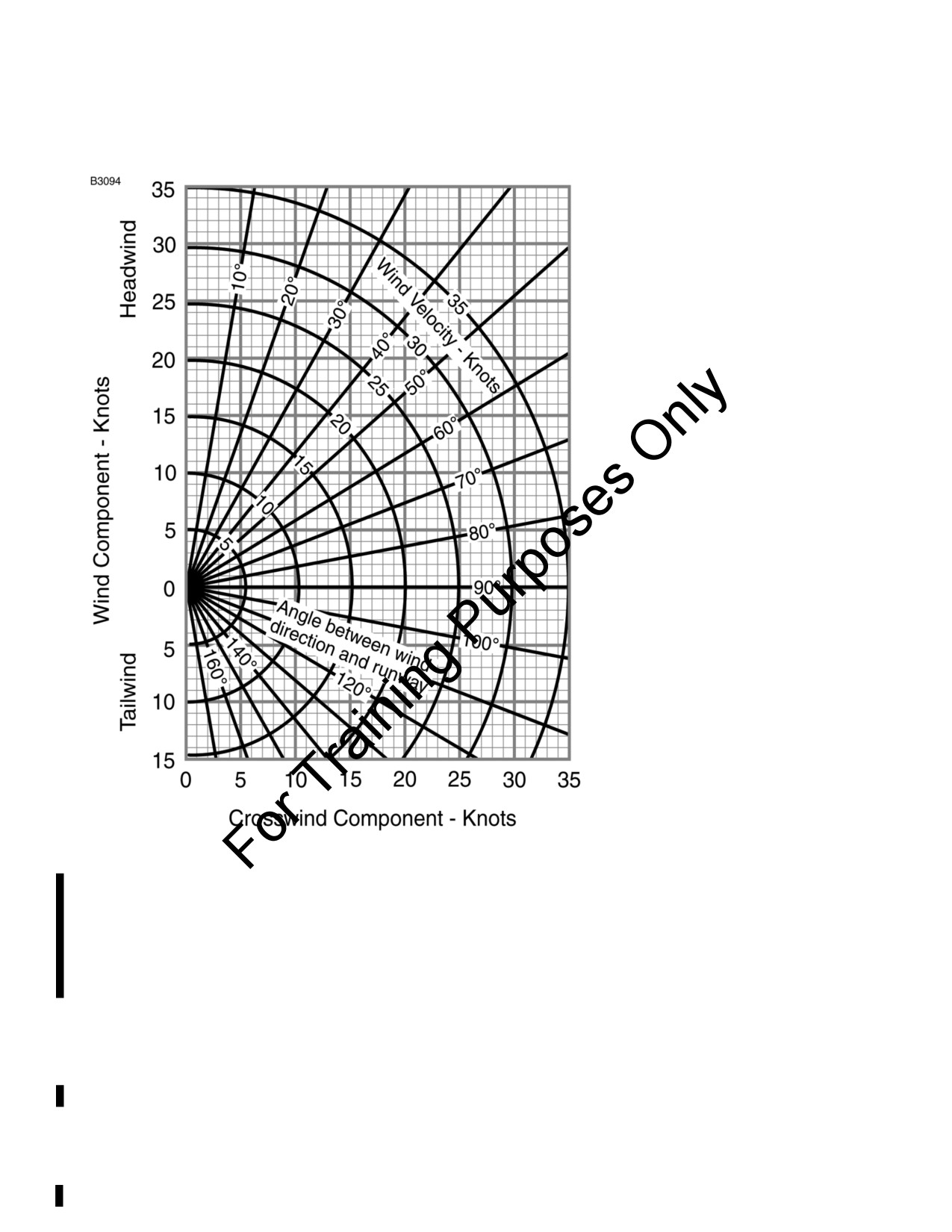
SECTION 5
CESSNA
PERFORMANCE
MODEL 172S NAV III
KAP 140 AUTOPILOT
CROSSWIND COMPONENT
MAXIMUM DEMONSTRATED CROSSWIND VELOCITY
Takeoff, Flaps UP
20 KNOTS
Takeoff, Flaps 10°
20 KNOTS
Landing, Flaps 10°
20 KNOTS
Landing, Flaps FULL
15 KNOTS
Figure 5-4*
5-14
U.S.
172SPHAUS-05

CESSNA
SECTION 5
MODEL 172S NAV III
PERFORMANCE
KAP 140 AUTOPILOT
SHORT FIELD TAKEOFF DISTANCE
AT 2550 POUNDS
CONDITIONS:
Flaps 10°
Full Throttle prior to brake release.
Paved, Level, Dry Runway
Lift Off:
51 KIAS
Zero Wind
Speed at 50 Feet:
56 KIAS
0°C
10°C
20°C
30°C
40°C
Total
Total
Total
Total
Total
Feet
Feet
Feet
Feet
Feet
Pressure
Gnd
To
Gnd
To
Gnd
To
Gnd
To
Gnd
To
Altitude -
Roll
Clear
Roll
Clear
Roll
Clear
Roll
Clear
Roll
Clear
Feet
Feet
50
Feet
50
Feet
50
Feet
50
Feet
50
Foot
Foot
Foot
Foot
Foot
Obst
Obst
Obst
Obst
Obst
Sea Level
860
1465
925
1575
995
1690
1070
1810
1150
1945
1000
940
1600
1010
1720
1090
1850
1170
1990
1260
2135
2000
1025
1755
1110
1890
1195
2035
1285
2190
1380
2355
3000
1125
1925
1215
2080
1310
2240
1410
2420
1515
2605
4000
1235
2120
1335
2295
1440
2480
1550
2685
1660
2880
5000
1355
2345
1465
2545
1585
2755
1705
2975
1825
3205
6000
1495
2605
1615
2830
1745
3075
1875
3320
2010
3585
7000
1645
2910
1785
3170
1920
3440
2065
3730
2215
4045
8000
1820
3265
1970
3575
2120
3880
2280
4225
2450
4615
NOTE
• Short field technique as specified in Section 4.
• Prior to takeoff from fields above 3000 feet pressure altitude, the mixture
should be leaned to give maximum RPM in a full throttle, static run-up.
• Decrease distances 10% for each 9 knots headwind. For operation with
tailwinds up to 10 knots, increase distances by 10% for each 2 knots.
• For operation on dry grass runway, increase distances by 15% of the
“ground roll” figure.
Figure 5-5* (Sheet 1 of 3)
172SPHAUS-05
U.S.
5-15

SECTION 5
CESSNA
PERFORMANCE
MODEL 172S NAV III
KAP 140 AUTOPILOT
SHORT FIELD TAKEOFF DISTANCE
AT 2400 POUNDS
CONDITIONS:
Flaps 10°
Full Throttle prior to brake release.
Paved, Level, Dry Runway
Lift Off:
48 KIAS
Zero Wind
Speed at 50 Feet:
54 KIAS
0°C
10°C
20°C
30°C
40°C
Total
Total
Total
Total
Total
Feet
Feet
Feet
Feet
Feet
Pressure
Gnd
To
Gnd
To
Gnd
To
Gnd
To
Gnd
To
Altitude -
Roll
Clear
Roll
Clear
Roll
Clear
Roll
Clear
Roll
Clear
Feet
Feet
50
Feet
50
Feet
50
Feet
50
Feet
50
Foot
Foot
Foot
Foot
Foot
Obst
Obst
Obst
Obst
Obst
Sea Level
745
1275
800
1370
860
1470
925
1570
995
1685
1000
810
1390
875
1495
940
1605
1010
1720
1085
1845
2000
885
1520
955
1635
1030
1760
1110
1890
1190
2030
3000
970
1665
1050
1795
1130
1930
1215
2080
1305
2230
4000
1065
1830
1150
1975
1240
2130
1335
2295
1430
2455
5000
1170
2015
1265
2180
1360
2355
1465
2530
1570
2715
6000
1285
2230
1390
2410
1500
2610
1610
2805
1725
3015
7000
1415
2470
1530
2685
1650
2900
1770
3125
1900
3370
8000
1560
2755
1690
3000
1815
3240
1950
3500
2095
3790
NOTE
• Short field technique as specified in Section 4.
• Prior to takeoff from fields above 3000 feet pressure altitude, the mixture
should be leaned to give maximum RPM in a full throttle, static run-up.
• Decrease distances 10% for each 9 knots headwind. For operation with
tailwinds up to 10 knots, increase distances by 10% for each 2 knots.
• For operation on dry grass runway, increase distances by 15% of the
“ground roll” figure.
Figure 5-5* (Sheet 2)
5-16
U.S.
172SPHAUS-05

CESSNA
SECTION 5
MODEL 172S NAV III
PERFORMANCE
KAP 140 AUTOPILOT
SHORT FIELD TAKEOFF DISTANCE
AT 2200 POUNDS
CONDITIONS:
Flaps 10°
Full Throttle prior to brake release.
Paved, Level, Dry Runway
Lift Off:
44 KIAS
Zero Wind
Speed at 50 Feet:
50 KIAS
0°C
10°C
20°C
30°C
40°C
Total
Total
Total
Total
Total
Feet
Feet
Feet
Feet
Feet
Pressure
Gnd
To
Gnd
To
Gnd
To
Gnd
To
Gnd
To
Altitude -
Roll
Clear
Roll
Clear
Roll
Clear
Roll
Clear
Roll
Clear
Feet
Feet
50
Feet
50
Feet
50
Feet
50
Feet
50
Foot
Foot
Foot
Foot
Foot
Obst
Obst
Obst
Obst
Obst
Sea Level
610
1055
655
1130
705
1205
760
1290
815
1380
1000
665
1145
720
1230
770
1315
830
1410
890
1505
2000
725
1250
785
1340
845
1435
905
1540
975
1650
3000
795
1365
860
1465
925
1570
995
1685
1065
1805
4000
870
1490
940
1605
1010
1725
1090
1855
1165
1975
5000
955
1635
1030
1765
1110
1900
1195
2035
1275
2175
6000
1050
1800
1130
1940
1220
2090
1310
2240
1400
2395
7000
1150
1985
1245
2145
1340
2305
1435
2475
1540
2650
8000
1270
2195
1370
2375
1475
2555
1580
2745
1695
2950
NOTE
• Short field technique as specified in Section 4.
• Prior to takeoff from fields above 3000 feet pressure altitude, the mixture
should be leaned to give maximum RPM in a full throttle, static run-up.
• Decrease distances 10% for each 9 knots headwind. For operation with
tailwinds up to 10 knots, increase distances by 10% for each 2 knots.
• For operation on dry grass runway, increase distances by 15% of the
“ground roll” figure.
Figure 5-5* (Sheet 3)
172SPHAUS-05
U.S.
5-17
SECTION 5
CESSNA
PERFORMANCE
MODEL 172S NAV III
KAP 140 AUTOPILOT
MAXIMUM RATE OF CLIMB
AT 2550 POUNDS
CONDITIONS:
Flaps UP
Full Throttle
Pressure
Rate of Climb - FPM
Climb Speed
Altitude -
- KIAS
-20°C
0°C
20°C
40°C
Feet
Sea Level
74
855
785
710
645
2000
73
760
695
625
560
4000
73
685
620
555
495
6000
73
575
515
450
390
8000
72
465
405
345
285
10,000
72
360
300
240
180
12,000
72
255
195
135
---
NOTE
Mixture leaned above
3000 feet pressure altitude
for
maximum RPM.
Figure 5-6*
5-18
U.S.
172SPHAUS-05

CESSNA
SECTION 5
MODEL 172S NAV III
PERFORMANCE
KAP 140 AUTOPILOT
TIME, FUEL AND DISTANCE TO CLIMB
AT 2550 POUNDS
CONDITIONS:
Flaps UP
Full Throttle
Standard Temperature
From Sea Level
Pressure
Climb
Rate of
Temp
Altitude
Speed
Climb
Time
Fuel Used
Distance
°
C
Feet
KIAS
FPM
Minutes
Gallons
NM
Sea Level
15
74
730
0
0.0
0
1000
13
73
695
1
0.4
2
2000
11
73
655
3
0.8
4
3000
9
73
620
4
1.2
6
4000
7
73
600
6
1.5
8
5000
5
73
550
8
1.9
10
6000
3
73
505
10
2.2
13
7000
1
73
455
12
2.6
16
8000
-1
72
410
14
3.0
19
9000
-3
72
360
17
3.4
22
10,000
-5
72
315
20
3.9
27
11,000
-7
72
265
24
4.4
32
12,000
-9
72
220
28
5.0
38
NOTE
• Add 1.4 gallons of fuel for engine start, taxi and takeoff
allowance.
• Mixture leaned above 3000 feet pressure altitude for
maximum RPM.
• Increase time, fuel and distance by 10% for each 10°C
above standard temperature.
• Distances shown are based on zero wind.
Figure 5-7*
172SPHAUS-05
U.S.
5-19
SECTION 5
CESSNA
PERFORMANCE
MODEL 172S NAV III
KAP 140 AUTOPILOT
CRUISE PERFORMANCE
CONDITIONS:
2550 Pounds
Recommended Lean Mixture
Pressure
20°C BELOW
STANDARD
20°C ABOVE
Altitude
RPM
STANDARD TEMP
TEMPERATURE
STANDARD TEMP
Feet
%
%
%
MCP
KTAS
GPH
MCP
KTAS
GPH
MCP
KTAS
GPH
2000
2550
83
117
11.1
77
118
10.5
72
117
9.9
2500
78
115
10.6
73
115
9.9
68
115
9.4
2400
69
111
9.6
64
110
9.0
60
109
8.5
2300
61
105
8.6
57
104
8.1
53
102
7.7
2200
53
99
7.7
50
97
7.3
47
95
6.9
2100
47
92
6.9
44
90
6.6
42
89
6.3
4000
2600
83
120
11.1
77
120
10.4
72
119
9.8
2550
79
118
10.6
73
117
9.9
68
117
9.4
2500
74
115
10.1
69
115
9.5
64
114
8.9
2400
65
110
9.1
61
109
8.5
57
107
8.1
2300
58
104
8.2
54
102
7.7
51
101
7.3
2200
51
98
7.4
48
96
7.0
45
94
6.7
2100
45
91
6.6
42
89
6.4
40
87
6.1
6000
2650
83
122
11.1
77
122
10.4
72
121
9.8
2600
78
120
10.6
73
119
9.9
68
118
9.4
2500
70
115
9.6
65
114
9.0
60
112
8.5
2400
62
109
8.6
57
108
8.2
54
106
7.7
2300
54
103
7.8
51
101
7.4
48
99
7.0
2200
48
96
7.1
45
94
6.7
43
92
6.4
NOTE
•
Maximum
cruise
power using recommended lean
mixture is 75% MCP. Power settings above 75% MCP
are listed to aid interpolation. Operations above 75%
MCP must use full rich mixture.
•
Cruise speeds are shown for an airplane equipped with
speed fairings. Without speed fairings, decrease speeds
shown by 2 knots.
Figure 5-8 (Sheet 1 of 2)*
5-20
U.S.
172SPHAUS-05
CESSNA
SECTION 5
MODEL 172S NAV III
PERFORMANCE
KAP 140 AUTOPILOT
CRUISE PERFORMANCE
CONDITIONS:
2550 Pounds
Recommended Lean Mixture
Pressure
20°C BELOW
STANDARD
20°C ABOVE
Altitude
RPM
STANDARD TEMP
TEMPERATURE
STANDARD TEMP
Feet
%
%
%
MCP
KTAS
GPH
MCP
KTAS
GPH
MCP
KTAS
GPH
8000
2700
83
125
11.1
77
124
10.4
71
123
9.7
2650
78
122
10.5
72
122
9.9
67
120
9.3
2600
74
120
10.0
68
119
9.4
64
117
8.9
2500
65
114
9.1
61
112
8.6
57
111
8.1
2400
58
108
8.2
54
106
7.8
51
104
7.4
2300
52
101
7.5
48
99
7.1
46
97
6.8
2200
46
94
6.8
43
92
6.5
41
90
6.2
10,000
2700
78
124
10.5
72
123
9.8
67
122
9.3
2650
73
122
10.0
68
120
9.4
63
119
8.9
2600
69
119
9.5
64
117
9.0
60
115
8.5
2500
62
113
8.7
57
111
8.2
54
109
7.8
2400
55
106
7.9
51
104
7.5
49
102
7.1
2300
49
100
7.2
46
97
6.8
44
95
6.5
12,000
2650
69
121
9.5
64
119
8.9
60
117
8.5
2600
65
118
9.1
61
116
8.5
57
114
8.1
2500
58
111
8.3
54
109
7.8
51
107
7.4
2400
52
105
7.5
49
102
7.1
46
100
6.8
2300
47
98
6.9
44
95
6.6
41
92
6.3
NOTE
•
Maximum
cruise
power using recommended lean
mixture is 75% MCP. Power settings above 75% MCP
are listed to aid interpolation. Operations above 75%
MCP must use full rich mixture.
•
Cruise speeds are shown for an airplane equipped with
speed fairings. Without speed fairings, decrease speeds
shown by 2 knots.
Figure 5-8 (Sheet 2)*
172SPHAUS-05
U.S.
5-21

SECTION 5
CESSNA
PERFORMANCE
MODEL 172S NAV III
KAP 140 AUTOPILOT
RANGE PROFILE
45 MINUTES RESERVE
53 GALLONS USABLE FUEL
CONDITIONS:
2550 Pounds
Standard Temperature
Recommended Lean Mixture for Cruise at all altitudes
Zero Wind
NOTE
• This chart allows for the fuel used for engine start, taxi, takeoff and
climb, and the distance during a normal climb.
• Cruise speeds are shown for an airplane equipped with speed
fairings. Without speed fairings, decrease speeds shown by 2
knots.
Figure 5-9*
5-22
U.S.
172SPHAUS-05

CESSNA
SECTION 5
MODEL 172S NAV III
PERFORMANCE
KAP 140 AUTOPILOT
ENDURANCE PROFILE
45 MINUTES RESERVE
53 GALLONS USABLE FUEL
CONDITIONS:
2550 Pounds
Standard Temperature
Recommended Lean Mixture for Cruise at all altitudes
NOTE
This chart allows for the fuel used for engine start, taxi,
takeoff and climb, and the time during a normal climb.
Figure 5-10*
172SPHAUS-05
U.S.
5-23

SECTION 5
CESSNA
PERFORMANCE
MODEL 172S NAV III
KAP 140 AUTOPILOT
SHORT FIELD LANDING DISTANCE
AT 2550 POUNDS
CONDITIONS:
Flaps FULL
Zero Wind
Power IDLE
Paved, Level, Dry Runway
Maximum Braking
Speed at 50 ft:
61 KIAS
0°C
10°C
20°C
30°C
40°C
Total
Total
Total
Total
Total
Feet
Feet
Feet
Feet
Feet
Pressure
Gnd
To
Gnd
To
Gnd
To
Gnd
To
Gnd
To
Altitude -
Roll
Clear
Roll
Clear
Roll
Clear
Roll
Clear
Roll
Clear
Feet
Feet
50
Feet
50
Feet
50
Feet
50
Feet
50
Foot
Foot
Foot
Foot
Foot
Obst
Obst
Obst
Obst
Obst
Sea Level
545
1290
565
1320
585
1350
605
1380
625
1415
1000
565
1320
585
1350
605
1385
625
1420
650
1450
2000
585
1355
610
1385
630
1420
650
1455
670
1490
3000
610
1385
630
1425
655
1460
675
1495
695
1530
4000
630
1425
655
1460
675
1495
700
1535
725
1570
5000
655
1460
680
1500
705
1535
725
1575
750
1615
6000
680
1500
705
1540
730
1580
755
1620
780
1660
7000
705
1545
730
1585
760
1625
785
1665
810
1705
8000
735
1585
760
1630
790
1670
815
1715
840
1755
NOTE
• Short field technique as specified in Section 4.
• Decrease distances 10% for each 9 knots headwind. For
operation with tail winds up to
10 knots, increase
distances by 10% for each 2 knots.
• For operation on dry grass runway, increase distances
by 45% of the “ground roll” figure.
• If landing with flaps up, increase the approach speed by
9 KIAS and allow for 35% longer distances.
Figure 5-11*
5-24
U.S.
172SPHAUS-05
CESSNA
SECTION 6
MODEL 172S NAV III
WEIGHT AND BALANCE/
KAP 140 AUTOPILOT
EQUIPMENT LIST
WEIGHT AND BALANCE/
EQUIPMENT LIST
TABLE OF CONTENTS
Page
Introduction
6-3
Airplane Weighing Procedures
6-3
Airplane Weighing Form
6-5
Sample Weight and Balance Record
6-7
Weight And Balance
6-8
Baggage Tiedown
6-9
Sample Loading Problem
6-10
Loading Graph
6-12
Loading Arrangements
6-13
Internal Cabin Dimensions
6-14
Center Of Gravity Moment Envelope
6-15
Center of Gravity Limits
6-16
Comprehensive Equipment List
6-17/6-18
172SPHAUS-05
U.S.
6-1/6-2
CESSNA
SECTION 6
MODEL 172S NAV III
WEIGHT AND BALANCE/
KAP 140 AUTOPILOT
EQUIPMENT LIST
INTRODUCTION
This section describes the procedure for establishing the basic empty
weight and moment of the airplane. Sample forms are provided for
reference. Procedures for calculating the weight and moment for
various operations are also provided. For additional information
regarding Weight and Balance procedures, refer to the Aircraft Weight
and Balance Handbook (FAA-H-8083-1). A comprehensive list of
Cessna equipment available for this airplane is included at the back of
this section.
Specific information regarding the weight, arm, moment and installed
equipment for this airplane as delivered from the factory can be found
in the plastic envelope in the back of this POH.
WARNING
IT IS THE RESPONSIBILITY OF THE PILOT TO MAKE
SURE THE AIRPLANE IS LOADED PROPERLY.
OPERATION OUTSIDE OF PRESCRIBED WEIGHT AND
BALANCE LIMITATIONS COULD RESULT IN AN
ACCIDENT AND SERIOUS OR FATAL INJURY.
AIRPLANE WEIGHING PROCEDURES
1. Preparation:
a. Inflate tires to recommended operating pressures.
b. Defuel airplane. Refer to the Maintenance Manual.
c. Service engine oil as required to obtain a normal full
indication (approximately 7 quarts on dipstick).
d. Move sliding seats to the most forward position.
e. Raise flaps to the fully retracted position.
f.
Place all control surfaces in neutral position.
g.
Remove all non-required items from airplane.
(Continued Next Page)
172SPHAUS-05
U.S.
6-3
SECTION 6
CESSNA
WEIGHT AND BALANCE/
MODEL 172S NAV III
EQUIPMENT LIST
KAP 140 AUTOPILOT
AIRPLANE WEIGHING PROCEDURES (Continued)
2.
Level:
a. Place scales under each wheel (minimum scale capacity,
1000 pounds).
b. Deflate the nose tire and/or lower or raise the nose strut to
properly center the bubble in the level (Refer to Figure 6-1
Sheet 1).
3.
Weigh:
a. Weigh airplane in a closed hangar to avoid errors caused by
air currents.
b. With the airplane level and brakes released, record the
weight shown on each scale. Deduct the tare, if any, from
each reading.
4.
Measure:
a. Obtain measurement A by measuring horizontally (along the
airplane centerline) from a line stretched between the main
wheel centers to a plumb bob dropped from the firewall.
b. Obtain measurement B by measuring horizontally and
parallel to the airplane centerline, from center of nosewheel
axle, left side, to a plumb bob dropped from the line between
the main wheel centers. Repeat on right side and average
the measurements.
5.
Using weights from step 3 and measurements from step 4, the
Basic Empty Weight and C.G. can be determined by completing
Figure 6-1 (Sheet 2).
6.
Changes to the Airplane Weight and Balance due to alteration or
repair must be documented in a permanent record within the
POH similar to that shown in Figure 6-2.
7.
A new Basic Empty Weight and CG Arm based on actual airplane
weight (as weighed) is required after a major repair or alteration.
It is recommended that the airplane be weighed to verify Basic
Empty Weight and CG Arm at intervals not to exceed 5 years.
6-4
U.S.
172SPHAUS-05

CESSNA
SECTION 6
MODEL 172S NAV III
WEIGHT AND BALANCE/
KAP 140 AUTOPILOT
EQUIPMENT LIST
AIRPLANE WEIGHING FORM
Figure 6-1 (Sheet 1 of 2)
172SPHAUS-05
U.S.
6-5

SECTION 6
CESSNA
WEIGHT AND BALANCE/
MODEL 172S NAV III
EQUIPMENT LIST
KAP 140 AUTOPILOT
AIRPLANE WEIGHING FORM
Figure 6-1 (Sheet 2)
6-6
U.S.
172SPHAUS-05
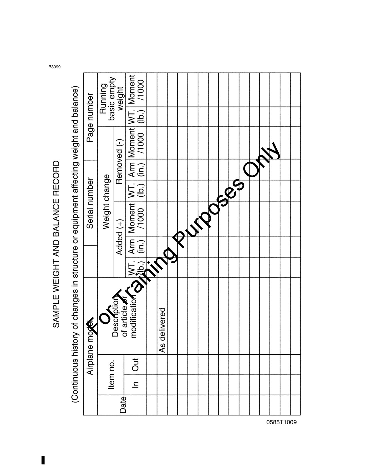
CESSNA
SECTION 6
MODEL 172S NAV III
WEIGHT AND BALANCE/
KAP 140 AUTOPILOT
EQUIPMENT LIST
SAMPLE WEIGHT AND BALANCE RECORD
Figure 6-2
172SPHAUS-05
U.S.
6-7
SECTION 6
CESSNA
WEIGHT AND BALANCE/
MODEL 172S NAV III
EQUIPMENT LIST
KAP 140 AUTOPILOT
WEIGHT AND BALANCE
The following information will enable you to operate your Cessna within
the prescribed weight and center of gravity limitations. To determine
weight and balance, use the Sample Loading Problem (Figure 6-3),
Loading Graph (Figure 6-4), and Center of Gravity Moment Envelope
(Figure 6-7) as follows:
Enter the appropriate basic empty weight and moment/1000 from the
weight and balance records for your airplane in the YOUR AIRPLANE
column of the Sample Loading Problem.
NOTE
In addition to the basic empty weight and moment noted on
these records, the C.G. arm (FS) is also shown, but need
not be used on the Sample Loading Problem. The moment
which is shown must be divided by 1000 and this value
used as the moment/1000 on the loading problem.
Use the Loading Graph to determine the moment/1000 for each
additional item to be carried; then list these on the loading problem.
NOTE
Loading Graph information for the pilot, passengers and
baggage is based on seats positioned for average
occupants and baggage loaded in the center of the
baggage areas as shown on the Loading Arrangements
diagram. For loadings which may differ from these, the
Sample Loading Problem lists fuselage stations (FS) for
these items to indicate their forward and aft C.G. range
limitations (seat travel and baggage area limitation). Refer
to Figures 6-5 and 6-6 for additional loading information.
Additional moment calculations, based on the actual weight
and C.G. arm (FS) of the item being loaded, must be made
if the position of the load is different from that shown on the
Loading Graph.
Total the weights and moments/1000 and plot these values on the
Center of Gravity Moment Envelope to determine whether the point
falls within the envelope, and if the loading is acceptable.
(Continued Next Page)
6-8
U.S.
172SPHAUS-05
CESSNA
SECTION 6
MODEL 172S NAV III
WEIGHT AND BALANCE/
KAP 140 AUTOPILOT
EQUIPMENT LIST
WEIGHT AND BALANCE (Continued)
BAGGAGE TIEDOWN
A nylon baggage net having four tiedown straps is provided as
standard equipment to secure baggage on the cabin floor aft of the rear
seat (baggage area A) and in the aft baggage area (baggage area B).
Six eyebolts serve as attaching points for the net. Two eyebolts for the
forward tiedown straps are mounted on the cabin floor near each
sidewall just forward of the baggage door approximately at station FS
90; two eyebolts are installed on the cabin floor slightly inboard of each
sidewall approximately at FS 107; and two eyebolts are located below
the aft window near each sidewall approximately at FS 107. A placard
on the baggage door defines the weight limitations in the baggage
areas.
When baggage area A is utilized for baggage only, the two forward floor
mounted eyebolts and the two aft floor mounted eyebolts (or the two
eyebolts below the aft window) may be used, depending on the height
of the baggage. When baggage is carried in the baggage area B only,
the aft floor mounted eyebolts and the eyebolts below the aft window
should be used. When baggage is loaded in both areas, all six eyebolts
should be utilized.
172SPHAUS-05
U.S.
6-9

SECTION 6
CESSNA
WEIGHT AND BALANCE/
MODEL 172S NAV III
EQUIPMENT LIST
KAP 140 AUTOPILOT
SAMPLE LOADING PROBLEM
WEIGHT AND MOMENT
TABULATION
SAMPLE
YOUR
ITEM DESCRIPTION
AIRPLANE
AIRPLANE
Weight
Moment
Weight
Moment
(lbs)
(lb-ins/
(lbs)
(lb-ins/
1000)
1000)
1 - Basic Empty Weight
(Use the data pertaining to your airplane
as it is presently equipped. Includes
unusable fuel and full oil)
1642
62.6
2 - Usable Fuel (At 6 Lbs./Gal.)
- Standard Fuel - 53 Gallons Maximum
- Reduced Fuel - 35 Gallons
210
10.1
3 - Pilot and Front Passenger (FS 34 to 46)
340
12.6
4 - Rear Passengers (FS 73)
310
22.6
5 - *Baggage “A” (FS 82 to 108)
120 Pounds Maximum
56
5.3
6 - *Baggage “B” (FS 108 to 142)
50 Pounds Maximum
7 - RAMP WEIGHT AND MOMENT
2558
113.2
8 - Fuel allowance for engine start, taxi and
runup
-8.0
-0.4
9 - TAKEOFF WEIGHT AND MOMENT
(Subtract Step 8 from Step 7)
2550
112.8
10 - Locate this point (2550 at 112.8) on the Center of Gravity Moment Envelope,
and since this point falls within the envelope, the loading is acceptable.
*The maximum allowable combined weight capacity for baggage in areas “A”
and “B” is 120 pounds.
Figure 6-3 (Sheet 1 of 2)
6-10
U.S.
172SPHAUS-05

CESSNA
SECTION 6
MODEL 172S NAV III
WEIGHT AND BALANCE/
KAP 140 AUTOPILOT
EQUIPMENT LIST
SAMPLE LOADING PROBLEM
NOTE
When several loading configurations are representative of
your operations, it may be useful to fill out one or more of
the above columns so specific loadings are available at a
glance.
Figure 6-3 (Sheet 2)
172SPHAUS-05
U.S.
6-11

SECTION 6
CESSNA
WEIGHT AND BALANCE/
MODEL 172S NAV III
EQUIPMENT LIST
KAP 140 AUTOPILOT
LOADING GRAPH
NOTE
Line representing adjustable seats shows the pilot and
front seat passenger center of gravity on adjustable seats
positioned for average occupant. Refer to the Loading
Arrangements diagram for forward and aft limits of
occupant C.G. range.
Figure 6-4
6-12
U.S.
172SPHAUS-05

CESSNA
SECTION 6
MODEL 172S NAV III
WEIGHT AND BALANCE/
KAP 140 AUTOPILOT
EQUIPMENT LIST
LOADING ARRANGEMENTS
*Pilot and front seat passenger center of gravity on adjustable seats
positioned for average occupant. Numbers in parentheses indicate
forward and aft limits of occupant center of gravity range.
**Arm measured to the center of the areas shown.
NOTE
• The usable fuel C.G. arm is located at FS 48.00.
• The aft baggage wall (approximate FS 108.00) or aft
baggage wall (approximate FS 142.00) can be used as
a convenient interior reference point for determining the
location of baggage area fuselage stations.
• To achieve an airplane loading within the utility category,
it may be necessary to remove the rear passenger seat
assembly from the airplane. Refer to Figure 6-9 for
applicable weight and arm.
Figure 6-5
172SPHAUS-05
U.S.
6-13
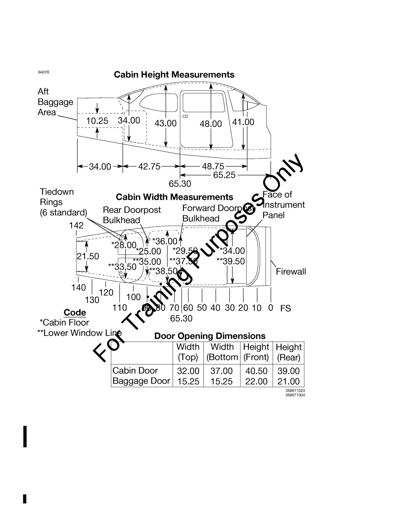
SECTION 6
CESSNA
WEIGHT AND BALANCE/
MODEL 172S NAV III
EQUIPMENT LIST
KAP 140 AUTOPILOT
INTERNAL CABIN DIMENSIONS
NOTE
• Maximum allowable floor loading is 200 pounds per
square foot.
• All dimensions shown are in inches.
Figure 6-6
6-14
U.S.
172SPHAUS-05

CESSNA
SECTION 6
MODEL 172S NAV III
WEIGHT AND BALANCE/
KAP 140 AUTOPILOT
EQUIPMENT LIST
CENTER OF GRAVITY MOMENT ENVELOPE
Figure 6-7
172SPHAUS-05
U.S.
6-15

SECTION 6
CESSNA
WEIGHT AND BALANCE/
MODEL 172S NAV III
EQUIPMENT LIST
KAP 140 AUTOPILOT
CENTER OF GRAVITY LIMITS
Figure 6-8
6-16
U.S.
172SPHAUS-05
CESSNA
SECTION 6
MODEL 172S NAV III
WEIGHT AND BALANCE/
KAP 140 AUTOPILOT
EQUIPMENT LIST
COMPREHENSIVE EQUIPMENT LIST
Figure 6-9 is a comprehensive list of all Cessna equipment which is available for
the Model 172S airplane equipped with Garmin G1000 Integrated Cockpit System
and KAP 140 Autopilot (if installed)
(Serials
172S9810 thru 172S10467 and
172S10469 thru 172S10506 and 172S10508 thru 172S10639 and 172S10641 thru
172S10655). This comprehensive equipment list provides the following information
in column form:
In the ITEM NO column, each item is assigned a coded number. The first two
digits of the code represent the identification of the item within Air Transport
Association Specification
100 (11 for Paint and Placards; 24 for Electrical
Power; 77 for Engine Indicating, etc.). These assignments also correspond to
the Maintenance Manual chapter for the airplane. After the first two digits, items
receive a unique sequence number (01, 02, 03, etc.). After the sequence
number, a suffix letter is assigned to identify equipment as a required item, a
standard item or an optional item.
Suffix letters are as follows:
R = Required items or equipment for FAA certification (14 CFR 23 or 14
CFR 91).
S = Standard equipment items.
O = Optional equipment items replacing required or standard items.
A = Optional equipment items which are in addition to required or
standard items.
In the EQUIPMENT LIST DESCRIPTION column, each item is assigned a
descriptive name to help identify its function.
In the REF DRAWING column, a Cessna drawing number is provided which
corresponds to the item.
NOTE
If additional equipment is to be installed, it must be done in
accordance with the reference drawing, service bulletin or a separate
FAA approval.
In the WT LBS and ARM INS columns, information is provided on the weight (in
pounds) and arm (in inches) of the equipment item.
NOTE
• Unless otherwise indicated, true values (not net change values)
for the weight and arm are shown. Positive arms are distances aft
of the airplane datum; negative arms are distances forward of the
datum.
• Asterisks (*) in the weight and arm column indicate complete
assembly installations. Some major components of the assembly
are listed on the lines immediately following. The sum of these
major components does not necessarily equal the complete
assembly installation.
172SPHAUS-05
U.S.
6-17/6-18

CESSNA
SECTION 6
MODEL 172S NAV III
WEIGHT AND BALANCE/
KAP 140 AUTOPILOT
EQUIPMENT LIST
REF
WT
ARM
ITEM NO
EQUIPMENT LIST DESCRIPTION
DRAWING
LBS
INS.
11 - PAINT AND PLACARDS
11-01-S
PAINT, OVERALL WHITE WITH COLOR STRIPE
0500531
19.2*
95.4*
- OVERALL WHITE COLOR
18.4
91.5
- COLOR STRIPING
0.8
135.9
21 - AIR CONDITIONING
21-01-S
VENTILATORS, ADJUSTABLE, CABIN AIR
0513575-2
1.7
60.0
21-02-S
CABIN HEATER SYSTEM, SHROUDED MUFFLER
0550365
2.5
-20.75
TYPE
21-03-R
FORWARD AVIONICS COOLING FAN - MC24B3
3930379
0.5
12.7
21-04-R
AFT AVIONICS COOLING FAN
3940397
1.1
109.0
22 - AUTO FLIGHT
22-01-O
KAP 140 TWO AXIS AUTOPILOT
- KAP 140 TWO AXIS AUTOPILOT
3930492
2.6
12.0
- KS-270C PITCH SERVO
0501145-1
4.2
171.3
- KS-272C PITCH TRIM SERVO
0501153-1
4.1
175.5
- KS-271C ROLL SERVO
3940400-1
3.6
54.2
23 - COMMUNICATIONS
23-01-S
STATIC DISCHARGE WICKS, (SET OF 10)
0501048-1
0.4
143.2
23-02-R
AUDIO/INTERCOM/MARKER BEACON
- GMA 1347 AUDIO PANEL
3930377
1.7
16.3
- CI-102 MARKER BEACON ANTENNA
3960193-5
0.5
129.0
23-03-R
NAV/COM/GPS #1 COMPUTER
3921155
- GIA 63 INTEGRATED AVIONICS UNIT
3940397
4.9
113.3
- CI 2480-200 VHF COMM/GPS ANTENNA
3960220-3
0.5
61.2
23-04-S
NAV/COM/GPS #2 COMPUTER
3921155
- GIA 63 INTEGRATED AVIONICS UNIT
3940397
4.9
113.3
- CI 2580-410 VHF COMM/GPS/XM ANTENNA
3960220-4
0.5
61.2
24 - ELECTRICAL POWER
24-01-R
ALTERNATOR, 28 VOLT, 60 AMP, -9910591-11
0550365
10.0
-29.0
24-02-R
BATTERY, 24 VOLT, 12.75 AMP HOUR
0518006
23.2
-5.0
24-03-R
POWER DISTRIBUTION MODULE S3100-344
0518006
6.4*
-2.5*
- ALTERNATOR CONTROL UNIT
AC2101
0.2
-2.5
- MASTER CONTACTOR
X61-0007
0.7
-2.5
- STARTER CONTACTOR
X61-0012
0.7
-2.5
- AMMETER TRANSDUCER
CS3100
0.1
-2.0
24-04-S
BATTERY, STANDBY - AVT 200413
0518025
14.0
11.2
Figure 6-9 (Sheet 1 of 6)
172SPHAUS-05
U.S.
6-19