Military reference books and manuals (2009-2023, Volume 7) - page 29
MRAP VEHICLES HANDBOOK
• Ensure drivers avoid abrupt steering maneuvers (slow down prior to
turning) and know proper maneuvering techniques if the MRAP vehicle
leaves the roadway.
• Never allow radio antennas to contact high-tension power lines.
Crew/passengers:
• Practice rollover and water egress drills to standard.
• Maintain situational awareness and use crew/passenger coordination
measures.
• Know beforehand how your combat locks work.
U.S. UNCLASSIFIED
REL NATO, GCTF, ISAF, MCFI, ABCA
29
For Official Use Only
MRAP VEHICLES HANDBOOK
Chapter 7
Employment Considerations
There are three major considerations for employing the mine-resistant
ambush-protected (MRAP) vehicle during tactical operations:
• Survivability and increased firepower that can be maneuvered around the
battlefield.
• Effects of restricted terrain on maneuver.
• Challenges of combining mounted and dismounted operations.
The MRAP vehicle presents leaders with new tactical and accidental risks to
mitigate. In balancing these risks and benefits, the commander thoroughly evaluates
the factors of mission, enemy, terrain and weather, troops and support available,
time available, and civil considerations (METT TC). Company leadership must
know the latest developments in threat tactics against mounted patrols and convoys.
Unit tactical standing operating procedures and the Center for Army Lessons
Learned unclassified and classified Web sites and publications are other sources to
consider for tactics, techniques, and procedures (TTP). Below are some general
considerations based on historical and current observations from both Operation
Enduring Freedom (OEF) and Operation Iraqi Freedom (OIF):
•
All-round security and observation coupled with an aggressive crew and
passenger security and weapons posture are normally the biggest enemy
deterrent.
•
Trends indicate that vehicles without all-round security are individually
targeted for attack. The enemy can even target individual vehicles with
poor security from within larger convoys.
•
The vehicle suspension should be monitored to detect deterioration and
failure. Vehicle passenger or materiel loads should be closely monitored.
•
Commanders should carefully consider the mix of vehicles on missions to
maximize the strengths of each type of vehicle and the associated order of
march during movement. The MRAP vehicle provides good protection
but significantly limits visibility. Generally, the MRAP vehicle should
lead any movement.
•
An emerging technique from theater is using a casualty
evacuation-prepared MRAP vehicle toward the end of a convoy to care
for any injured Soldiers. The space inside the vehicle makes it very
suitable for litter casualties.
•
Some commanders in theater are finding the MRAP vehicle makes an
excellent mobile and protected tactical command post vehicle.
U.S. UNCLASSIFIED
REL NATO, GCTF, ISAF, MCFI, ABCA
31
For Official Use Only
CENTER FOR ARMY LESSONS LEARNED
Force Protection
Force protection is irrevocably linked to mission success. Consequently, it must
always be an important consideration in the planning and execution of missions that
employ motorized forces. The balance between the protection of vehicles and
occupants, observation, and the employment of weapons is critical.
Heavily armored vehicles, especially wheeled vehicles with extra armor such as the
MRAP vehicle, severely limit crew and passenger observation in restrictive and
urban terrain. They can also limit weapons employment at close ranges.
Both shoulder-fired antitank rocket launchers and improvised explosive devices
(IEDs) can defeat many armored vehicles and can defeat the MRAP vehicle when
carefully employed.
Insurgent and terrorist enemy forces target vehicles with poor security because they
seem easier to destroy and less likely to respond effectively.
Commanders must stress that increased survivability only comes in part from
armor, security posture, and the rapid response to threats:
• Leaders must strive to compensate for reduced observation; gunners play
a larger role in creating 360-degree awareness for the crew.
• Bounding overwatch when practical and traveling overwatch at all other
times are keys to the 360-degree awareness and rapid response to threats.
• Communication among the MRAP vehicles in the formation is essential.
The MRAP vehicle is designed with a series of protection mechanisms to enhance
the survival and increase the mission effectiveness of its crew and passengers:
• The initial layer is designed to prevent explosive and projectile
penetration and consists of the geometric shape of the body to deflect the
blast combined with opaque and transparent ballistic armor to prevent
hull penetration. The elevated body combines with the shape to provide
the occupants with stand-off from the blast.
• The second layer mitigates when the first layer is overmatched and
consists of fire suppression mechanisms to quickly extinguish fires and
prevent secondary explosions.
• The third layer minimizes the effects of shock and blast on the occupants
and consists of shock-absorbing seats that limit the transfer of energy to
the body and seat restraints that keep the occupant secured in the vehicle.
• A final layer of protection is provided by the individual Soldier and
consists of personal protective equipment such as helmet, body armor,
eye protection, hearing protection, etc.
All these mechanisms must work in unison to achieve full MRAP protective
capabilities. Although MRAP vehicles provide a significant increase in force
protection, Soldiers and leaders must not become complacent and remove their
U.S. UNCLASSIFIED
REL NATO, GCTF, ISAF, MCFI, ABCA
32
For Official Use Only
MRAP VEHICLES HANDBOOK
personal protective equipment while riding in the vehicle. To do so only increases
the risk of injury when the MRAP vehicle is attacked.
MRAP Vehicle Communication Considerations
MRAP vehicle crew communication is paramount to smooth vehicle operation:
• Commanders must consider how dismounted Soldiers will communicate
with the mounted crew and other dismounted Soldiers.
• All MRAP systems are equipped with vehicle intercom systems for the
driver, vehicle commander, gunner, and at least one occupant.
• It is essential that commanders consider the challenges of
communications and ensure procedures are established to maintain
effective communications between the crew, passengers, and dismounted
forces.
• Squads and platoons should develop and rehearse communications plans
between mounted and dismounted elements as a part of mission
preparation.
MRAP Vehicle Equipment Load Plans
Externally stowed items:
• Leaders must ensure that any externally stowed items are secured from
theft and do not constitute a fire hazard if the MRAP is attacked by IEDs,
anti-armor ordnance, or other flammable weapons.
• External stowage should be minimized or modified to lessen the threat of
vehicle fire and to not restrict the view or movement of gunners or
passengers providing security.
Internally stowed items:
• All items stored inside the vehicle must be secured to prevent them from
becoming secondary missiles in the event of an IED strike or a rollover.
Loose equipment can seriously injure Soldiers.
• Commanders should minimize or eliminate the number of flammable
items stowed inside the vehicle.
MRAP Vehicle Urban Patrolling
The basic planning considerations for both mounted and dismounted patrolling are
almost identical. Although MRAP vehicles will typically have the advantage of
mobility and firepower over dismounted elements, communications and observation
pose difficulties, as previously noted. The more heavily armored MRAP vehicle
might be at greater risk in the urban environment unless closely supported by
dismounted forces. Therefore, this environment calls for integrating dismounted
with mounted patrol elements:
U.S. UNCLASSIFIED
REL NATO, GCTF, ISAF, MCFI, ABCA
33
For Official Use Only
CENTER FOR ARMY LESSONS LEARNED
• The enhanced mobility allows greater and faster area of operations (AO)
saturation and expansion of control.
• Integrating vehicles with foot patrols allows for increased sustainment
loads.
• Lighter, faster infantry forces have a greater chance of capturing or
killing lightly armed insurgents; mounted firepower provides support or
moves to block escaping or flanking enemy.
• Mounted elements increase patrol flexibility and versatility.
• Units employing the MRAP vehicle as part of a patrol in stability
operations should always operate in sections of at least two vehicles.
Other considerations for urban operations include the following:
• Avoid contact with overhead power lines.
• Avoid streets and alleys that are too narrow for particular vehicles.
Enemy forces can quickly identify this fact and plan their own routes
accordingly.
• Consider civilian vehicle and pedestrian traffic flow when planning patrol
routes. For each operation, consider the effects of military vehicles on
civilian traffic flow and patterns.
• Heavy vehicles can damage or even destroy civilian roads in the AO.
They can also damage or destroy underground and above ground utilities.
• Avoid using night-vision devices (NVDs) or blackout driving around
civilian traffic using white lights. Doing so endangers you and the
civilians, and they can see you anyway.
Reduced dismounted capability
Units that are not vehicular by tables of organization and equipment do not receive
additional Soldiers when issued an MRAP vehicle. This means they must supply
vehicle crews at the expense of troops available for dismounted operations. This
requires leaders to carefully plan based on their mission requirements.
When portions of the crew dismount (vehicle commander/gunner), the MRAP
vehicle is not fully capable. There is risk in operating an MRAP vehicle with a one-
or two-man crew. Leaders have devised creative solutions to keep tactical integrity
dismounted while maintaining mounted capability:
• Use operational rally points to secure vehicles to maximize a dismounted
presence.
• Designate one unit/squad mounted (filling the crew positions) while
another unit/squad is dismounted (filling the passenger positions) during
movement.
U.S. UNCLASSIFIED
REL NATO, GCTF, ISAF, MCFI, ABCA
34
For Official Use Only
MRAP VEHICLES HANDBOOK
Units in theater have also had success by training and rehearsing designated driver
and gunner teams to better synchronize vehicle movement and firing activities.
MRAP Vehicle Maintenance
Vehicle maintenance is critical to mission accomplishment. Poorly maintained
vehicles will fail. As they do, the OPTEMPO for functional vehicles increases
dramatically. Potential adverse effects can result:
• Reduced cargo or personnel carrying capacity, which reduces the combat
power ratio in the field.
• Increased service requirements and maintenance problems for overused
vehicles that have been maintained properly by their crews.
Initially, the MRAP vehicle will rely heavily on contract maintenance or field
service representatives (FSRs). This arrangement provides its own unique
challenges for units, particularly if they are not collocated on a FOB with their
parent unit or are competing with other units for priority of maintenance support.
Commanders should institute on-the-job training programs with their unit
mechanics and assigned FSRs.
Rough Terrain Driving
Drivers must become familiar with the various terrain conditions in the AO and
considerations for crossing the conditions encountered. Using good off-road driving
techniques is the best way to limit broken vehicle parts and getting stuck.
• The MRAP vehicle is not capable of high-speed travel on rough terrain.
• Depending on the MRAP variant, drivers should not operate the vehicle
at speeds greater than 5 to 10 mph on rough terrain unless a tactical
emergency exists.
• All drivers must be well trained in judging terrain and negotiating various
terrain conditions.
• Drivers must be extremely careful and mindful of the MRAP vehicle’s
speed when negotiating obstacles and aware of the vehicle’s high center
of gravity.
• Many operations and movements are at night, so driver training should
focus on using NVDs.
In addition, drivers should develop the following skills:
• Use momentum and understand the effects of vehicle speed.
• Know the vehicle’s capabilities and the impact of the on-board payload.
• Estimate and use proper speeds for the appropriate terrain conditions.
• Avoid sudden forward and braking thrusts.
U.S. UNCLASSIFIED
REL NATO, GCTF, ISAF, MCFI, ABCA
35
For Official Use Only
CENTER FOR ARMY LESSONS LEARNED
WARNING
The MRAP vehicle may become unstable and tip over when negotiating
vertical obstacles and deep ruts or potholes in the path of movement. Use
extreme caution and reduce vehicle speed.
Long-Range Operations
If the commander must conduct long-range operations, then he must be reasonably
sure of the range and expected time of the operation. This assurance allows him to
estimate logistic support accurately. The logistic resources required to support
long-range mounted operations will drive many aspects of the mission planning
(Classes III and IX, specifically). Additional considerations for long-range
operations include the following:
•
Mission range (mileage), duration, and expected vehicle fuel
consumption
•
Availability of resupply or support during operations
•
Planned vehicle loads (personnel and equipment)
•
Expected enemy situation
•
Terrain considerations such as:
º Road conditions
º Off-road travel conditions
º River crossings
º Bridges, tunnels, and choke points
•
Weather forecast:
º How it will affect movement
º Expected rainfall or snowfall
•
Presence of civilian vehicles in the area—vehicles normally encountered
in the AO
•
Communications ranges
•
Navigational considerations
•
Movement times:
º Day or night?
U.S. UNCLASSIFIED
REL NATO, GCTF, ISAF, MCFI, ABCA
36
For Official Use Only
MRAP VEHICLES HANDBOOK
º White light or NVD?
º Road or cross country?
• Recovery:
º Can the unit self recover?
º How will the unit deal with non-recoverable or disabled vehicles?
• Load plan for casualties or additional personnel in case vehicles are
destroyed or disabled
MRAP Vehicle Roof Hatch
Some MRAP vehicles are equipped with roof hatches. Roof hatches on MRAP
vehicles were designed for evacuation and not intended to be manned during
movement. Standing in an open roof hatch is not safe during movement due to the
small size of the hatches and the rough ride of the vehicle. (See the
Tank-Automotive and Armaments Command [TACOM] Safety-of-Use [SOU]
message below.)
TACOM SOU 08-020, MRAP, Escape Hatch -
WARNING
DEATH OR SERIOUS INJURY TO SOLDIERS OR DAMAGE TO ARMY
EQUIPMENT WILL OCCUR IF THE INSTRUCTIONS IN THIS
MESSAGE ARE NOT FOLLOWED.
Subject: Safety Of Use (SOU) Message, TACOM Control No. SOU 08-020,
Operational, Affecting the following Mine Resistant Ambush Protected (MRAP)
vehicles; BAE RG-33L Cat II NSN 2355-01-552-4677, IMG/Navistar MaxxPro
Cat I NSN 2355-01-553-4364, GDLS-C RG31A2 Mk5E Cat I NSN
235501-553-5581, and FPI Cougar/JERRV Cat II NSN 2320-01-552-5565.
Problem: Users are utilizing the emergency hatches located on the roof of the
vehicles as additional manned weapon stations. The escape hatches were not
designed to be modified for this purpose. Operating the vehicle with a person
standing out of the emergency escape hatch puts that person at a greater
risk of injury or death in the event of an accident or rollover. The escape
hatches on MRAPs are generally located inside the danger zone of radio and
countermeasure antennae. Utilizing the escape hatches as a manned weapon
station places the individual in danger due to the high levels of radiation
generated by the radio and countermeasure antennae.
User Actions: Cease the practice of using escape hatches as manned
weapons stations. Refrain from all attempts to modify the escape hatches in any
way to mount weapon systems. Remove any add-on equipment, and return the
escape hatches to their original configuration.
U.S. UNCLASSIFIED
REL NATO, GCTF, ISAF, MCFI, ABCA
37
For Official Use Only

CENTER FOR ARMY LESSONS LEARNED
Weapons Dead Space
Figure 7-1: This figure shows the shape of weapons deadspace on a typical
CAT I MRAP vehicle as measured from the weapon mounted on the turret.
Figure 7-2: This figure shows the shape of weapons deadspace on a typical
CAT II MRAP vehicle as measured from the weapon mounted on the turret.
U.S. UNCLASSIFIED
REL NATO, GCTF, ISAF, MCFI, ABCA
38
For Official Use Only
MRAP VEHICLES HANDBOOK
MRAP Vehicle Safety
Vehicular operations pose a new set of tactical and accident risks. Commanders
must consider this when planning operations and use the risk management process
to mitigate those risks.
Vehicle tip or rollover
MRAP vehicles have much larger profiles and weights than the vehicles they
replaced in theater. Take into account the mission criticality, MRAP vehicle
mission profiles, MRAP vehicle mission weights, ground pressures, weather, and
terrain.
Perform a rollover drill rehearsal with the gunner and crew prior to every
movement during rainy season. Heavy rains in theater may cause unpaved roads to
loosen and give way under the weight of the MRAP vehicle, especially if there is a
steep embankment or canal running alongside the road. MRAP vehicle crews
should practice rollover drills to standard. Be proficient and learn to work as a
team.
Ensure all personnel wear seatbelts, protective ensemble, and headgear. The risk of
fatality is three times greater for Marines, Sailors, and Soldiers who do not wear a
seatbelt during tactical vehicle operations (OIF/OEF CY 03-04, United States Army
Center for Health Promotion and Preventive Medicine study). Seatbelts allow the
driver to remain in a position from which to stabilize an out-of-control vehicle.
Gunner restraints prevent the gunner from becoming a potential fatality as a direct
result of being ejected from the interior, causing death on impact or crushing from
the MRAP vehicle.
Ensure all required equipment inside the vehicle is properly stowed and secured.
Interior occupants can sustain injuries from flying equipment, which makes
securing loads particularly important since objects inside the cab will become
deadly flying missiles should a rollover occur.
Use a ground guide through tight areas, when tactical conditions permit.
Unlock combat doors when around bodies of water if the tactical situation permits.
This will allow rescuers to enter the vehicle.
Fire hazards
While fire suppression systems are under consideration, all vehicles will have fire
extinguishers. The first priority for fire extinguishers should be to extinguish fires
on personnel or to extinguish fire in parts of the vehicle that allow the evacuation of
passengers. Crews must know how to react to a fire. Fire extinguishers should be
readily available on all vehicles. Consider mounting fire extinguishers near an
egress point. Be aware of the placement of flammable materials.
Dismounted troops near or under the vehicle
The crew must be continuously aware of dismounted troops around their vehicle.
Dismounted troops must make their presence known to the crew. Soldiers should
never lie under the vehicle or around the wheel wells. They must always be able to
U.S. UNCLASSIFIED
REL NATO, GCTF, ISAF, MCFI, ABCA
39
For Official Use Only
CENTER FOR ARMY LESSONS LEARNED
quickly move or roll away if a vehicle moves suddenly. Despite the crews’
understanding, an MRAP vehicle crew that is in contact with the enemy may react
before realizing a Soldier is under its vehicle.
Crew-served weapon proficiency
Vehicles often are issued with crew-served weapons. Anyone who will potentially
operate the weapons system must be trained at a minimum to load, clear, reduce
stoppage, and engage targets. This procedure will:
• Ensure crew-served weapons will always be manned in the event of a
wounded gunner.
• Ensure Soldiers do not have negligent discharges due to a lack of
training.
Composite risk assessment
Incorporate the potential for rollovers during risk assessments by evaluating bridges
and terrain along the route:
• Be alert and always use caution on roads close to bodies of water.
• Always consider allowing greater clearance when traveling along the
edge of the road.
• Assess the potential for low hanging power lines.
• Ensure hazards are briefed prior to the mission and brief options for
alternate or bypass routes.
Steering
Many rollovers occur when drivers panic and overcorrect their steering when
reacting to an emergency or to a wheel going off the pavement’s edge. At highway
speeds, overcorrecting or excessive steering can cause the driver to lose control,
which can force the vehicle to slide sideways and roll over. Sudden vehicle
maneuvers are particularly risky since the speed and a load shift can make the
vehicle unstable.
Proper maneuvering
At some point, your vehicle may drift off the roadway onto the shoulder or you may
steer onto the shoulder to avoid a collision. There may be a drop-off of several
inches from the edge of the road to the shoulder. Most shoulders provide less
traction than the roadway surface. They may be quite narrow and consist of loose
gravel, grass, or mud. Despite these variables, pulling off onto the shoulder and
returning to the roadway can be done safely. Practice the following proper
procedures:
• If you run the two right or left wheels off the paved roadway, keep a firm
grip on the steering wheel.
U.S. UNCLASSIFIED
REL NATO, GCTF, ISAF, MCFI, ABCA
40
For Official Use Only
MRAP VEHICLES HANDBOOK
•
Keep the vehicle traveling straight ahead.
•
Straddle the edge of the pavement. You must fight the tendency of the
wheels to pull toward soft shoulders. You also must resist the urge to
immediately whip the vehicle back onto the pavement.
•
Ease off the accelerator pedal so the vehicle slows down.
•
Avoid braking, if possible; if braking is necessary, use a gentle squeeze
braking application so you can control steering.
•
Before returning to the pavement, visually check ahead, to the sides, and
to the rear. Unless some object beside the road poses a serious threat of a
collision, avoid trying to return to the roadway immediately.
•
Move the off-road tires out about 1 l/2 to 2 feet away from the pavement
edge.
•
When it is safe and your speed is under control, turn the wheel quickly
about a quarter turn to the right or left as necessary. This lets the tire
climb the pavement edge and get back on the roadway.
•
As soon as the front tires are back on the roadway, counter steer quickly
to maintain your proper lane.
•
Reduce speeds when negotiating turns.
•
Avoid sudden vehicle maneuvers, overcorrecting, or excessive steering
that can result in loss of control that may cause a maneuver initiated
rollover.
•
Use caution on rural roads. When a vehicle goes off a rural road, the
vehicle can overturn when it strikes a ditch or embankment or is tripped
by soft soil.
•
Road shoulders in the Middle East do not meet U.S. standards and may
collapse under the weight of the MRAP vehicle, especially when the road
is above grade and can fall to lower ground (ditches and canals).
•
MRAP vehicle crews must maintain situational awareness and use vehicle
crew coordination. The vehicle commander and the gunner may often be
able to better determine the closeness of the vehicle to the edge of the
road than the driver. They should not hesitate to alert the driver if he is
getting too close to the edge of the road.
•
Use caution when crossing bridges that are unrated (get prior guidance
from combat engineers).
Tire pressure
Improperly inflated or worn tires can be especially dangerous because they inhibit
your ability to maintain vehicle control, the most important factor in reducing the
chance of rollover. Worn tires may cause the vehicle to slide sideways off the road
U.S. UNCLASSIFIED
REL NATO, GCTF, ISAF, MCFI, ABCA
41
For Official Use Only

CENTER FOR ARMY LESSONS LEARNED
on wet or slippery pavement and increase its risk of rolling over. Improper tire
inflation can accelerate tire wear and can even lead to tire failure. It is important to
maintain your tire pressure in accordance with the operator’s manual and replace
tires when necessary.
Vehicle crashes
Vehicle crashes includes crashing into terrain, obstacles, and other vehicles. This is
especially true for backing up in a vehicle with significantly reduced visibility.
Ensure drivers are properly trained and briefed on the anticipated terrain for the
operation. Operate vehicles as a crew. Do not let drivers move vehicles alone unless
it is mission essential. Use ground guides where tactically sound.
Falls
Soldiers should use three points of contact when on top of the vehicle due to its
height. Soldiers should not jump from the top of an MRAP vehicle.
Vehicle antennas
Antennas on the MRAP vehicle must be lowered or protected from contact with
power lines; serious injury or death as well as vehicle damage can occur.
Power Line Antenna Strike
• 4 blown tires
• scorching
Figure 7-3
Smashed and pinched extremities
Some MRAP doors are not hydraulic or do not have positive stops and can swing
free, breaking or cutting off fingers. Soldiers must be aware of personnel to the rear
of the vehicle when opening the rear door or dropping the ramp.
U.S. UNCLASSIFIED
REL NATO, GCTF, ISAF, MCFI, ABCA
42
For Official Use Only

MRAP VEHICLES HANDBOOK
HAND INJURIES
• Extremely heavy doors
• Metal edges
• Not cushioned
• Not restrained
Figure 7-4
Additional Information
Safety of use messages (SOUM)-U.S. Army Materiel Command’s Logistic Web
portal for SOUM is:
SOUM>. (Use Ctrl F and search for MRAP.)
Logistics Assistance Representative (LAR) Web links:
• Iraq:
larmap.cfm#swa>
• Afghanistan:
larmap.cfm#uzbafghn>
U.S. UNCLASSIFIED
REL NATO, GCTF, ISAF, MCFI, ABCA
43
For Official Use Only

MRAP VEHICLES HANDBOOK
Chapter 8
Tactical Manning
The seating capacity of the mine-resistant ambush-protected (MRAP) category
(CAT) I vehicle is 6 passengers, and the seating capacity for the CAT II vehicle
protected movement variant is 8 to10 passengers. Units may opt to make seat
configuration adjustments based on mission, model, and manufacturer of the MRAP
vehicle they are operating. The following diagrams show the most common
passenger seating configuration for an interim brigade combat team (IBCT);
passengers may be forward or inward facing.
CAT I: R&S, Maneuver
Vehicle
Commander (VC)
Driver (D)
Gunner (G)
4 Passengers
One passenger may be
lost to add special
equipment
CAT II: Maneuver/
CAT II:
Protected Movement
Ambulance
Vehicle
Vehicle
Driver (D)
Commander (VC)
Driver (D)
Commander (VC)
Gunner (G)
2 Passengers
8 Passengers
4 Litters
One passenger may be
lost to add special
equipment
Figure 8-1
Following is an example of one way to cross-load an IBCT rifle platoon into eight
MRAP CAT I vehicles. Some platoon-size units may not receive this many MRAP
vehicles; this example serves as a baseline for unit consideration. Modifications
must be made to fit each unit’s specific task organization, fielding, and mission. A
table of organization and equipment (TO&E) 39-man platoon with 1 medic leaves 8
open seats.
U.S. UNCLASSIFIED
REL NATO, GCTF, ISAF, MCFI, ABCA
45
For Official Use Only
CENTER FOR ARMY LESSONS LEARNED
1st Squad
.50 Cal / MK-19
PL / RTO / FO
0-2 Open Seats
D- RM
VC - PL
D- RM
VC - 1SL
G - AR
G -M203
- Med
- RTO
- B TL
- AR
- A TL
- M230
2nd Squad
.50 Cal / MK-19
3-5 Open Seats
D- RM
VC - 2SL
D- RM
VC - A TL
G - AR
G -M203
- B TL
- M203
- (OPEN)
- AR
- (OPEN)
- (OPEN)
3rd Squad
3-5 Open Seats
D- RM
VC - 3 SL
D- RM
VC - ATL
G - AR
G -AR
- M203
- M203
- (OPEN)
- B TL
- (OPEN)
- (OPEN)
Weapons Squad
PSG
2-4 Open Seats
D- AT
VC - WSL
D- AT
VC - PSG
G -M240
G -M240
- AG
- AB
- AG
- AB
- (OPEN)
- (OPEN)
Figure 8-2
The above seating is an example that may best support unit integrity for mounted
operations to include mounted combat patrol and outer cordon and traffic control
point operations. The above seating assumes the platoon has two crew-served
weapons (.50 cal and MK-19). A TO&E 39-man platoon with 1 forward observer
leaves 8 to 16 open seats.
U.S. UNCLASSIFIED
REL NATO, GCTF, ISAF, MCFI, ABCA
46
For Official Use Only

MRAP VEHICLES HANDBOOK
1st Section
.50 Cal / MK-19
PL / RTO / FO
0 Open Seats
D- 1/ RM
VC - 1 SL
D- W / AT
G -1 /AR
G -1/ M203
- 2 SL
- 2 / BTL
- AB
- RTO
- 2 / RM
-Med
2nd Section
0 Open Seats
D- AG
VC - WSL
D- AG
G -M240
G -M240
- 2 / ATL
- 2 / M203
- 3 / ATL
- 3 / M203
- 2 / RM
- 3 / RM
3rd Section
.50 Cal / MK-19
PSG
2 Open Seats
D- AB
VC - PSG
D- 1/ RM
G -1 / AR
G -1/ M203
- 3 / M203
- W / AT
- 3 SL
- 3 / BTL
- 3 / RM
- 3 / AR
Figure 8-3
The above seating is an example that may best support dismounted operations such
as raid, search, or leader engagements. Units should consider requesting CAT II
support to maximize dismounted Soldiers, using two to four CAT I vehicles as
escort and overwatch. The above seating assumes the platoon has two crew-served
weapons (.50 cal and MK-19) and the seventh seat is available in the vehicle. A
TO&E 39-man platoon with 1 medic leaves 2 open seats.
U.S. UNCLASSIFIED
REL NATO, GCTF, ISAF, MCFI, ABCA
47
For Official Use Only

MRAP VEHICLES HANDBOOK
Chapter 9
Load Plans
This section is divided into two parts. Part one provides basic diagrams and
equipment lists for units’ use in developing their specific mine-resistant
ambush-protected (MRAP) vehicle load plans using unit standing operating
procedures and directives. Part two provides a detailed example of an MRAP
vehicle-specific load plan for a category (CAT) I and CAT II MRAP variant.
While the MRAP vehicle is larger than the up-armored high-mobility multipurpose
wheeled vehicle (HMMWV) (UAH), there are still many space claims for radios,
improvised explosive device-defeat systems, and mission equipment packages. The
final load configuration is dependent upon vendor, category, and modifications
made after testing. The diagram below is furnished to record load plans used by a
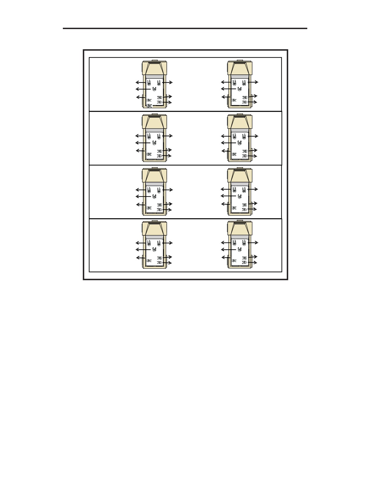
unit in its current situation.
CAT I
CAT II
Figure 9-1
U.S. UNCLASSIFIED
REL NATO, GCTF, ISAF, MCFI, ABCA
49
For Official Use Only
CENTER FOR ARMY LESSONS LEARNED
Equipment Lists
Vehicle items:
Cotton bag, for jack and tools
Bag, tool, cotton duct
Extension, jack handle
Handle, mechanical jack
Jack, scissors, hand
Pliers, slip joint
Screwdriver, cross-tip
Screwdriver, flat-tip
Wrench, adjustable
Wrench, ratchet
Wrench, wheel lug
Fire extinguisher
Bag assembly, pamphlet
Technical Manual 9-2320-387-10
Folder, equipment record
Max tool kit, combination tool
Hydraulic winch controller cable
Slave cable
Warning triangles, set
Tow chains or towing straps
Tow bar (if equipped)
Sledge hammer
Ax
U.S. UNCLASSIFIED
REL NATO, GCTF, ISAF, MCFI, ABCA
50
For Official Use Only
MRAP VEHICLES HANDBOOK
Shovel
Bolt cutters
Gloves, wire handlers
Air horn
Spotlight
Laser pointer
Combat lifesaver bag
Infrared strobe light
Can, fuel, 5 gallon
Litter
9-line medical evacuation “cheat” card
Other
Detainee kit (1 per MRAP vehicle):
15 flex cuffs
15 blindfolds (cravat bandage)
Detainee paperwork with document protectors
DA 2823, Sworn Statement
Coalition Apprehension Form
Platoon detainee startup sheet
25 feet 550 cord
15 Ziploc bags, 1-gallon size
15 shoe tags
Black Sharpie marker
Heavy medical scissors
Digital camera
U.S. UNCLASSIFIED
REL NATO, GCTF, ISAF, MCFI, ABCA
51
For Official Use Only
CENTER FOR ARMY LESSONS LEARNED
4 plastic trash bags
Latex gloves (CAT I - 6 pair; CAT II - 10 pair)
Other
Pickup zone marking kit (one per MRAP vehicle):
Carrying bag or case
VS-17 panel
2 smoke grenades
6 chem-lite spinners
Strobe light
Other
Traffic control point (TCP) kit (one per MRAP vehicle):
2 rolls concertina wire
Handheld metal detector (2 per patrol)
2 large vehicle search mirror
1 small vehicle search mirror
Spike strip ( 1 per patrol)
Extra flex cuffs
Megaphone (1 per patrol)
TCP signs
#1 Vehicle “Coalition Checkpoint Ahead”
#2 Vehicle “STOP…Search Area”
#3 Vehicle “STOP”
5 traffic cones
Ex-Spray kit
Platoon detainee startup sheet
Other
U.S. UNCLASSIFIED
REL NATO, GCTF, ISAF, MCFI, ABCA
52
For Official Use Only
MRAP VEHICLES HANDBOOK
Weapons and ammunition:
Crew-served weapon, mounted
800 rounds for crew-served weapon (minimum)
Rifle, 5.56-mm (in gunner’s turret)
M-136 (AT-4) anti-tank missile
2 red star cluster
2 green star cluster
Fragmentation grenades
Smoke grenades
Other
Crew sustainment load:
1 case bottled water x 1 day
1 case meals, ready-to-eat x 1 day
Rucksack or assault pack x # crewmembers
Other
U.S. UNCLASSIFIED
REL NATO, GCTF, ISAF, MCFI, ABCA
53
For Official Use Only

CENTER FOR ARMY LESSONS LEARNED
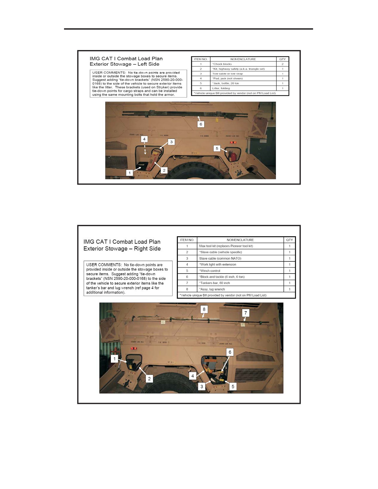
Example Combat Load Plans for CAT I and CAT II MRAP Vehicles
International Military and Government (IMG) MaxxPro CAT I
Figure 9-2
Figure 9-3
U.S. UNCLASSIFIED
REL NATO, GCTF, ISAF, MCFI, ABCA
54
For Official Use Only
MRAP VEHICLES HANDBOOK
Figure 9-4
Figure 9-5
U.S. UNCLASSIFIED
REL NATO, GCTF, ISAF, MCFI, ABCA
55
For Official Use Only
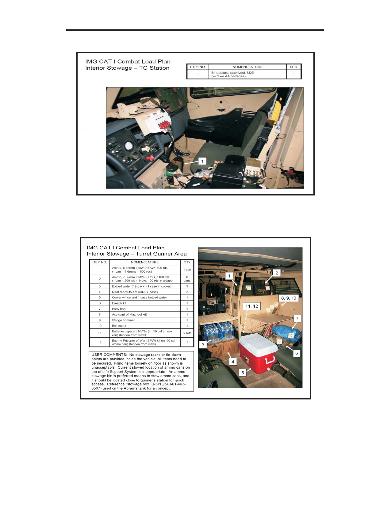
CENTER FOR ARMY LESSONS LEARNED
Figure 9-6
Figure 9-7
U.S. UNCLASSIFIED
REL NATO, GCTF, ISAF, MCFI, ABCA
56
For Official Use Only

MRAP VEHICLES HANDBOOK
Figure 9-8
Figure 9-9
U.S. UNCLASSIFIED
REL NATO, GCTF, ISAF, MCFI, ABCA
57
For Official Use Only

CENTER FOR ARMY LESSONS LEARNED
AT-4s.
are
Figure 9-10
Caiman
Caiman 6X6 Combat Load Plan
Exterior Stowage - Top
Figure 9-11
U.S. UNCLASSIFIED
REL NATO, GCTF, ISAF, MCFI, ABCA
58
For Official Use Only

MRAP VEHICLES HANDBOOK
Caiman 6X6 Combat Load Plan
Exterior Stowage - Left Side
Figure 9-12
Caiman 6X6 Combat Load Plan
Exterior Stowage - Right Side
Figure 9-13
U.S. UNCLASSIFIED
REL NATO, GCTF, ISAF, MCFI, ABCA
59
For Official Use Only

CENTER FOR ARMY LESSONS LEARNED
Caiman 6X6 Combat Load Plan
Interior Stowage - Driver Station
Figure 9-14
Caiman 6X6 Combat Load Plan
Interior Stowage - TC Station
Figure 9-15
U.S. UNCLASSIFIED
REL NATO, GCTF, ISAF, MCFI, ABCA
60
For Official Use Only

MRAP VEHICLES HANDBOOK
Caiman 6X6 Combat Load Plan
Interior Stowage - Troop Compartment (Left)
AT-4s
Figure 9-16
Caiman 6X6 Combat Load Plan
Interior Stowage -
Troop Compartment (Right)
Figure 9-17
U.S. UNCLASSIFIED
REL NATO, GCTF, ISAF, MCFI, ABCA
61
For Official Use Only

CENTER FOR ARMY LESSONS LEARNED
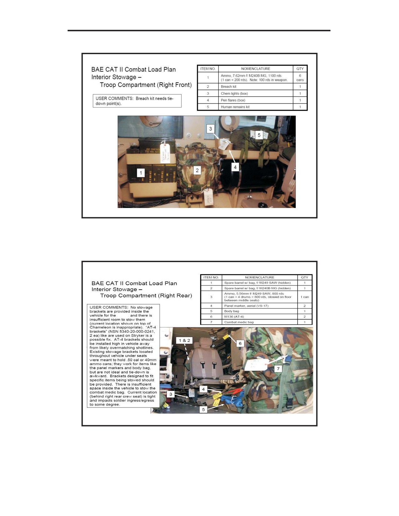
RG33 CAT II
Figure 9-18
Figure 9-19
U.S. UNCLASSIFIED
REL NATO, GCTF, ISAF, MCFI, ABCA
62
For Official Use Only
MRAP VEHICLES HANDBOOK
Figure 9-20
AT-4s
Figure 9-21
U.S. UNCLASSIFIED
REL NATO, GCTF, ISAF, MCFI, ABCA
63
For Official Use Only

CENTER FOR ARMY LESSONS LEARNED
Figure 9-22
U.S. UNCLASSIFIED
REL NATO, GCTF, ISAF, MCFI, ABCA
64
For Official Use Only

MRAP VEHICLES HANDBOOK
Chapter 10
Individual Protective Measures
(Information in this chapter is taken from a briefing by Lt. Col. Wayne A. Sinclair,
United States Marine Corps, titled “The Last Defense - Vehicle Survivability
Against Mines and IEDs.”)
Individual protective measures enhance one’s chance of surviving an encounter
with an improvised explosive device (IED) regardless of the type of vehicle. These
universal survivability measures can make the difference between being carried
away and walking away from an IED encounter.
Seatbelts
Figure 10-1
Given the violent forces exerted on the human body during vertical acceleration, a
crash, or a vehicle rollover, the ability to remain restrained to a stable surface is an
essential component of safety and survival.
Either the traditional or retractable diagonal seatbelts or the more effective
four-point seat harness restraints offered by the mine-resistant ambush-protected
(MRAP) vehicle can prove cumbersome given the bulk of flak jackets and
chest-worn equipment. Nevertheless, purposeful modifications to modular
lightweight load-carrying equipment (MOLLE)-weave equipment configurations
can allow for easier wear. With consistent practice, this essential element of tactical
discipline will become second nature.
Concerns about one’s ability to rapidly exit a vehicle must be tempered by the
knowledge that seatbelts prevent occupants from being slammed into vehicle roofs,
U.S. UNCLASSIFIED
REL NATO, GCTF, ISAF, MCFI, ABCA
65
For Official Use Only

CENTER FOR ARMY LESSONS LEARNED
doors, and windshields. Post-IED analysis reveals that simply remaining conscious
offers occupants the best chance to escape from a burning or submerged vehicle.
Personal Protective Equipment
Eye protection
- High speed debris and sand can
cause temporary or even permanent blindness.
Ear protection
- Ruptured ear drums lead to
disorientation after a strike.
Body armor and helmet - Provide protection from
fragmentation, impingement, and cranial trauma.
Figure 10-2
Eyes and ears are particularly vulnerable to fragmentation and overpressure injuries
during a blast. Inner-ear ruptures further contribute to a victim’s disorientation in
the critical minutes following a strike. Helmets and body armor provide essential
protection against primary fragmentation, the blunt trauma associated with
secondary missiles, and impacts during a vehicle rollover.
Keep a safe separation between body parts and external armor. Body armor may not
be able to prevent serious injury or death if arms, shoulders, and head rest against
the outer skin of an armored vehicle at the time of a nearby explosion.
Driving Posture
Drivers are particularly susceptible to injury during a mine or IED strike. The
steering wheel, control levers, pedals, and confined knee space all constitute serious
blunt trauma hazards during vertical acceleration. An erect posture mitigates spinal
injuries and keeps the steering wheel clear from causing traumatic strikes to one’s
chest and torso. Calculated security halts serve as stretch breaks and can offset the
fatigue that comes from prolonged PPE wear and proper spinal posture.
U.S. UNCLASSIFIED
REL NATO, GCTF, ISAF, MCFI, ABCA
66
For Official Use Only

MRAP VEHICLES HANDBOOK
Remain clear of steering wheel
- Potential
impingement and injury to chest.
Spinal alignment
- Sit up straight; remaining
upright significantly lowers effects of acceleration
on the back and neck.
Mitigate fatigue
- Proper rest, frequent security
halts, and hydration.
Field of view - Mirror adjustments, blind spots.
Figure 10-3
Passenger Area
Figure 10-4
Seating posture and seatbelts are also important for MRAP vehicle passengers.
Vertical acceleration plays havoc on an unrestrained and cluttered crew
compartment (see Figure 10-4).
U.S. UNCLASSIFIED
REL NATO, GCTF, ISAF, MCFI, ABCA
67
For Official Use Only

CENTER FOR ARMY LESSONS LEARNED
Passengers distracted or lacking situational awareness due to personal music
devices and an unfamiliarity with the location of fire extinguishers, first aid
kits—and in this case, the five available escape hatches of a 4x4 Cougar—are a
threat to themselves and the mission.
Future MRAP variants may have foot straps or stirrups attached to the seats.
Occupants should use these if equipped, since having the feet off the floor offers
more protection in a blast.
Vehicle Preparation
Pressure release “valves”
- Top venting
of vehicles allows for overpressure
release from a hull rupture.
Sandbags still work
- Covered with rubber
matting and placed on most vulnerable
horizontal surfaces (e.g, HMMWV floors).
Secured equipment
- Tie down and secure
loose equipment, ammo, weapons, etc. -
keep only essential material in crew
compartments.
Unobstructed visibility
- Keep transparent
armor (ballistic glass) clean.
Engaged a-driver - Dedicated
roadwatcher and assistant driver.
Figure 10-5
Enhanced survivability involves teamwork. Collective, disciplined vehicle
preparations mitigate injuries and increase survival rates considerably.
Deadly overpressure buildups associated with a hull breach or floor rupture should
be vented though an open gunner’s ring or, lacking that, another top hatch left
slightly open or set at “combat lock.”
Sandbags provide additional protection from high-speed fragmentation on vehicle
floors and prevent shattered heels from buckled floor armor.
Loose equipment and supplies pose secondary missile threats, causing additional
and totally preventable injuries. (The clutter found in the HMMWV shown in
Figure 10-5 was not staged and included a tow bar, which is not only a potential
source of injuries but also can trap an individual inside the vehicle.)
At three to four inches thick, transparent armor—otherwise known as ballistic
glass—can distort visibility under the best circumstances. Ensuring glass is
spotless, along with a dedicated road watcher who doubles as the assistant driver,
U.S. UNCLASSIFIED
REL NATO, GCTF, ISAF, MCFI, ABCA
68
For Official Use Only

MRAP VEHICLES HANDBOOK
will significantly improve the chances that IEDs and other threats will be identified
in sufficient time to avoid or react effectively.
Fire presents another danger. JP 8—universal fuel—has a flash point 30 degrees
lower than diesel. In essence, when warmed to 100 degrees Fahrenheit, JP 8 will
produce vapors subject to a flash ignition. Consider the following
• Externally carried fuel cans on troop vehicles present considerable risk.
• Never carry fuel inside compartments or the trunk of a HMMWV.
• Jerry cans are plastic and very susceptible to rupture during an IED strike,
creating an instant inferno that has no chance of being extinguished by
the on-board automatic fire suppression systems. The puncturing of a
five-gallon Jerry can by a hot fragment can turn a survivable IED strike
into a catastrophe.
• Fire extinguishers must be functional and secured.
• Auto fire-suppression systems should be part of regular pre-operational
checks and serviced with scheduled maintenance.
Do not mix spare fuel
with vehicles dedicated
to passenger or troop
transport; use a trailer.
Working, secured fire
extinguishers; check
auto-fire suppression
systems regularly.
Figure 10-6
Other Habits
Immediate action training often focuses on external threats in the wake of an IED
attack—5/25s, outward focused security, seeking a covered position. While these
steps can be essential due to the threat of ambushes that accompany a strike,
immediate attention must also be given to the internal concerns below. All these are
U.S. UNCLASSIFIED
REL NATO, GCTF, ISAF, MCFI, ABCA
69
For Official Use Only
CENTER FOR ARMY LESSONS LEARNED
based on observations and analysis of lethal IED events in Multi-National
Forces-West. The following concerns should become common practice:
• Know where every potential escape hatch is in the dark and how to
manipulate the handle to open it—or which ones must be used when
upside down or rolled onto one particular side.
• Given the frequency of concussions, temporary blindness, disorientation,
and unconsciousness following large IED strikes, never assume that all
occupants have safely exited a damaged vehicle—especially if it is
burning.
• If your vehicle is struck and on fire, the sequence of essential tasks is
escape, then accountability, then suppression of the fire, then first aid.
Leaders must assure Soldiers know and understand these steps.
• Stay in the tracks of the vehicle in front of you (whenever possible and
appropriate).
• Keep speeds below 35 mph.
Good Habits to Remember:
Rehearse post strike immediate "internal actions for vehicle crews and
passengers:
• Escape
• Accountability
• Fire suppression
• First aid
As a rule of thumb, follow the path of the vehicle in front.
Keep speeds down—the risk versus gain analysis is clearly in favor of slower
vehicle speeds.
U.S. UNCLASSIFIED
REL NATO, GCTF, ISAF, MCFI, ABCA
70
For Official Use Only
MRAP VEHICLES HANDBOOK
Chapter 11
Casualty Evacuation Procedures
Casualty evacuation (CASEVAC) is the evacuation of sick and wounded on a
nonstandard platform normally not manned by medical personnel or equipped with
medical sets kits and outfits designed for en route care.
The CASEVAC conversion kit (CCK) consists of two brackets for the litter-support
arms. These two brackets are permanently installed to the wall of the vehicle. The
two litter-support arms are stored on the vehicle until the CASEVAC kit is ready to
be used. There are two arm mounts inside the litter arms. The arms are attached to
the bracket, which is permanently installed to the wall of the vehicle. Secure the
casualty to the litter by using the casualty litter straps.
Loading and Unloading a Litter Casualty
Place the MRAP vehicle CCK into operation
Step 1. Attach the litter support arm to the front bracket that is already permanently
mounted on the wall. The litter support arm will slide easily onto the arm mount.
Step 2. Install the litter arm mounting pin through both the litter support arm and
the mount to secure the litter support arm to the front bracket.
Step 3. Pull out the end by pulling on the litter arm release pin to enable the end to
slide out. Pull it out enough so that it will accommodate the width of a litter.
Step 4. Load the casualty head first into the vehicle. Place the litter handles (the
handles located at the head of the casualty) onto the litter support arm. Slide the
litter support arm inward toward the wall to secure the litter so that the litter stop
cuffs over the litter handle.
Step 5. A second Soldier installs the other (rear) litter support arm while the first
Soldier, who is at the foot of the casualty, supports the litter in the air.
Step 6. The second Soldier installs the litter arm mounting pin to secure the litter
support arm to the bracket.
Step 7. The first Soldier, while supporting the weight of the litter, lowers the litter
onto the rear litter support arm. The second Soldier slides the litter support arm
inward toward the wall to secure the litter and the casualty so that the litter stop
cuffs over the litter handles, thus securing the litter casualty to the CCK.
Step 8. Unload the casualty in reverse sequence.
Loading and unloading a litter casualty using a spine board
Step 1. (For this portion, the CCK is already installed and configured to receive a
casualty with a litter already secured to the CCK. For this instruction, ensure the
casualty is secured using litter straps to the spine board and is prepared for
evacuation). From the start position with four personnel at each corner of the board,
the team approaches the rear entrance of the vehicle.
U.S. UNCLASSIFIED
REL NATO, GCTF, ISAF, MCFI, ABCA
71
For Official Use Only
CENTER FOR ARMY LESSONS LEARNED
Step 2. At the rear entrance, the team executes to a three-man semi-overhead carry
while one individual mounts the vehicle. The three-man team shuttles the casualty
on the spine board to the individual inside the vehicle.
Step 3. As the three-man team shuttles the casualty, the team will have to transition
to an overhead carry (one behind the other) as they continue to load the casualty
onto the litter that is already in place on the CCK. The team continues to slide the
casualty onto the litter and makes final adjustments to ensure that the litter is
secured to the CCK.
Step 4. Unload the casualty in reverse sequence.
U.S. UNCLASSIFIED
REL NATO, GCTF, ISAF, MCFI, ABCA
72
For Official Use Only
MRAP VEHICLES HANDBOOK
2/101 BCT MRAP Vehicle Lessons Learned BAE RG33L CAT II
CASEVAC
Issue: Using MRAP vehicle for CASEVAC
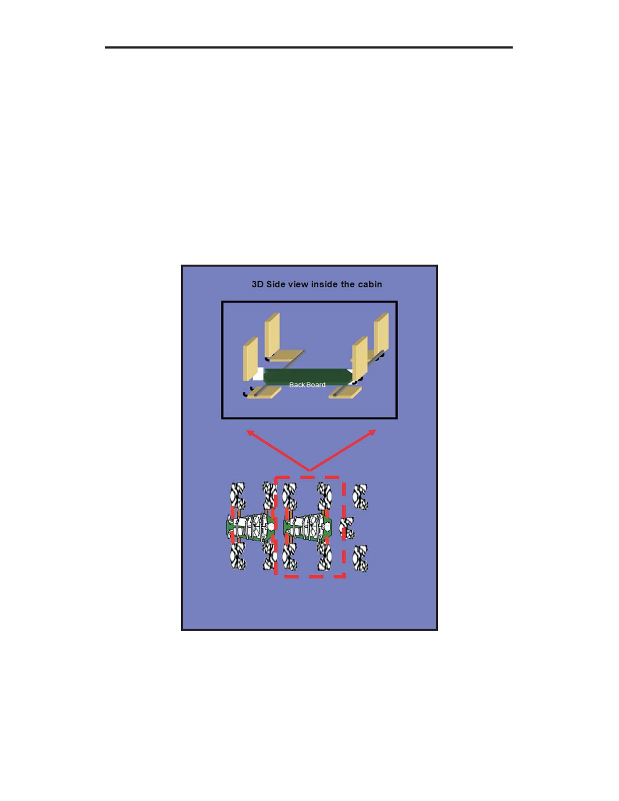
Recommendation: The best way to load a casualty is strapped to a backboard and
placed in the center of the vehicle atop 2"x4" wooden boards or a combination of
the cheater bars, tanker bar, and handles for the axe or sledge hammer. The items
form a bridge by placing them on the seats across from one another.
The above plan will allow up to two casualties.
The backboard can be stabilized and prevented from shifting back and forth by
using some simple straps fastened to the top of the seat.
Figure 11-1
U.S. UNCLASSIFIED
REL NATO, GCTF, ISAF, MCFI, ABCA
73
For Official Use Only
CENTER FOR ARMY LESSONS LEARNED
Task: Evacuate wounded from vehicle
Conditions: MRAP vehicle-equipped platoon/section is mounted either stationary
or moving, conducting operations. A vehicle is disabled due to enemy contact. An
occupant of the vehicle has been injured and must be evacuated.
Standards: Platoon suppresses the enemy, moves out of the engagement area if
possible, and establishes security. Squad/team members conduct first aid and
remove the casualty from the vehicle. Unit leader requests medical evacuation
(MEDEVAC), if necessary, and reports to higher headquarters.
Task Steps: Remove Casualty:
• Unit suppresses the enemy and moves out of the engagement area, if
possible.
• Once out of the engagement area or when the enemy is suppressed, unit
establishes security.
• Designated Soldiers move to the vehicle to treat and evacuate the
casualty.
Remove Casualty:
• Soldiers remove the casualty from the vehicle so as not to cause further
injury (one Soldier at the head and one near the feet).
• Soldiers administer first aid.
• Unit leader requests MEDEVAC if necessary.
• Unit leader reports the contact to higher headquarters.
Transport casualty:
• Soldiers load and secure Soldier on backboard using straps available.
• One Soldier places items to bridge the casualty between the seats (cheater
bar, axe handle, tanker bar).
• Soldiers load casualty head first, with one Soldier in the vehicle to
receive the casualty, one Soldier on each side, and one Soldier at the feet
of the casualty.
• Soldier in the vehicle guides the casualty over the backboard bridge and
secures the backboard using straps or ropes.
U.S. UNCLASSIFIED
REL NATO, GCTF, ISAF, MCFI, ABCA
74
For Official Use Only

MRAP VEHICLES HANDBOOK
3D Side view inside the
cabin
Back Board &
Casulty
Bridging
Anchor
Points
Back Board
Figure 11-3
Task #
Task
Manual
React to Contact (Visual, IED and
07-3-D3991
ARTEP 7-1-DRILL
Direct Fire
07-3-D3999
Establish Security at the Halt
ARTEP 7-1-DRILL
Conduct Consolidation and
07-2-D5027
ARTEP 7-10
Reorganization
Evacuate Wounded Personnel from
07-3-D3998
ARTEP 7-1-DRILL
Vehicle
07-9-0204
Treat and Evacuate Casualties
ARTEP 7-10
U.S. UNCLASSIFIED
REL NATO, GCTF, ISAF, MCFI, ABCA
75
For Official Use Only

MRAP VEHICLES HANDBOOK
Chapter 12
Recovery and Towing Operations and Damage Reporting
(Note: See Appendix A for specific vehicle variants.)
Figure 12-1
Many recovery operations consist of self-recovery methods, either when the vehicle
becomes stuck or when it has a mechanical failure or receives battle damage.
Mine-resistant ambush-protected (MRAP) vehicle recovery is easiest when the tires
still have traction and when crew members can help the vehicle move through the
original tire tracks.
When the MRAP vehicle is stuck in snow, sand, or mud, the crew can lower tire
pressure to increase traction. Using a second MRAP to help pull a stuck vehicle is
normally the quickest recovery method. The unit should always carry tow bars or
chains and shovels. It should have hooks or shackles attached to both ends for
anchoring to the vehicles. If possible, the patrol carries at least one tow bar for each
vehicle section to assist in long-range recovery.
When the MRAP vehicle is stuck in mud or sand, the unit uses pioneer tools to
emplace dry or solid matter under the tires for traction. Sandbags or other materials
can be dug into and under the wheels to assist traction. Units normally carry empty
sandbags for this purpose.
When conducting recovery, one section provides security while the other vehicle
makes the recovery. The recovery section decides before making the recovery
where the vehicle can go after it breaks loose.
The commander should make contingency plans for vehicles that cannot be repaired
or recovered. The company will make every attempt to recover the vehicle and
return it to where it can be repaired, if needed. The commander should make
contingency plans for vehicles that cannot be immediately repaired or recovered.
U.S. UNCLASSIFIED
REL NATO, GCTF, ISAF, MCFI, ABCA
77
For Official Use Only

CENTER FOR ARMY LESSONS LEARNED
• Use the thickest chains possible
• Tow straps are NOT recommended
• Move all personnel to a safe distance
away before applying tension to
chains or winch cables
Figure 12-2
Recovery Basics
Recovery is retrieving (freeing) immobile, inoperative, or abandoned equipment
from its current position and returning it to operation or to a maintenance site for
repair. These actions typically involve towing, lifting, or winching. Towing is
usually limited to moving equipment to the nearest forward operating base. The
amount and type of equipment used as the source of effort during any recovery
operation depends on the level of recovery. Drivers and crews should evaluate the
situation and determine if the crew can recover the vehicle before calling on
support from a higher level.
Levels of Recovery
Self-recovery
Self-recovery actions require using only the equipment’s assets. Self-recovery starts
at the location where the equipment becomes mired or disabled. The operator/crew
uses basic issue items and authorized allowance list or on-vehicle equipment items
to perform self-recovery. Self-recovery winches can be used to assist in a recovery
effort by providing stabilizing or holdback capabilities. (Note: The current winch is
not safe and should not be used in recovery operations.)
Procedures: See Appendix A.
Like-recovery
Like-recovery actions involve assistance (tow bar only) from a second, like, or
heavier class vehicle. Like-vehicle recovery is used when self-vehicle recovery
fails. Using like vehicles is usually the quickest method of recovery because they
are readily available. The principle is to use another piece of equipment of the same
weight class or heavier to extract or tow the mired equipment by using tow bars,
chains, or tow cables. When self-recovery and like-recovery are not practical or are
unavailable, use dedicated recovery assets.
U.S. UNCLASSIFIED
REL NATO, GCTF, ISAF, MCFI, ABCA
78
For Official Use Only
MRAP VEHICLES HANDBOOK
Procedures: Before towing any vehicle, refer to the vehicle technical manual. The
following are general rules for towing:
• Move towed loads at slow speed.
• Use a tow bar in preference to chains, ropes, or cables. Tow bars keep the
towed vehicle from running into the towing vehicle.
• Proceed slowly at 5 to 10 miles per hour because the towed vehicle may
skid on turns at higher speeds. Avoid quick stops.
• When using a tow bar, connect a safety chain between the two vehicles in
case the bar breaks or becomes disconnected.
• Do not have a driver or crew member in any towed vehicle unless using a
chain or cable.
WARNING
Never tow vehicles with caged brakes or damaged air brake systems using
like-vehicle towing procedures. Immediately call for wrecker support.
Dedicated recovery
Dedicated recovery actions require assistance from a vehicle specifically designed
and dedicated to recovery operations. Dedicated-recovery vehicles are used when
self-recovery or like-vehicle recovery is not possible because of the severity of the
situation, safety considerations, or the inability to use like-vehicle assets employed
in their primary mission.
Procedures: See Appendix A
U.S. Army National Ground Intelligence Center Anti-Armor Task Force
Battlefield Vehicle Forensics Program
The battlefield vehicle forensics (BVF) quick reference guide is designed to walk
you through the procedures and techniques for good forensics collection. The guide
and report form are located at the Reimer Digital Library and are available to
active, guard, reserve, Department of Army civilians, and approved Department of
Defense contractors on a case-by-case basis (go to
AATF-BVF/AATF-BVF.PPT>.
The purpose of the program is to provide:
• Historical enemy attack data to deploying or deployed units for their
future or current area of responsibility (AOR).
• Attack data for all weapon types used.
• Attack data on type of armor vehicle attacked.
U.S. UNCLASSIFIED
REL NATO, GCTF, ISAF, MCFI, ABCA
79
For Official Use Only
CENTER FOR ARMY LESSONS LEARNED
• Subject matter experts (SMEs) on threat anti-armor weapon systems
(small arms, rocket-propelled grenades, antitank guided missiles,
anti-armor improvised explosive devices, etc.).
Battlefield Vehicle Forensics Program
Soldiers (support specialty team, explosive ordnance disposal team, and weapons
inspection team) can be trained to collect high-value technical data from incident
sites and vehicles and casualties at incident sites. This data can then be used to:
• Identify exact weapon used
• Identify exact lethal effects of the weapon
• Develop technical improvements
• Change friendly tactics to avoid enemy weapons’ strengths and exploit
weapons’ weaknesses
• Collaborate with medical community
• Document the scene, measure the scene, photograph the scene, recover
evidence, and check documents
• Put recovered material in context
Main topic areas covered in the slide show located in Reimer Digital Library cover
the following topics:
• Overview of threat
• Battlefield vehicle forensics
• Attack scene investigation
• Sniper/small-arms attack scene investigation
U.S. UNCLASSIFIED
REL NATO, GCTF, ISAF, MCFI, ABCA
80
For Official Use Only

MRAP VEHICLES HANDBOOK
Appendix A
Recovery and Towing Operations
(Note: Information in this appendix is provided by the TRADOC Executive
Agency for Battle Damage Assessment Repair and Recovery.)
BAE Systems RG33 and RG33L
Figure A-1: BAE RG33
Figure A-2: BAE RG33L
General Information and Equipment Description
Due to the unique design of the BAE mine-resistant ambush-protected (MRAP)
vehicles, recovery personnel face several challenges when attempting to recover
these systems. These challenges include size, weight, route clearance, and design
issues.
The intent of this section is to provide procedures for recovering disabled vehicles
in emergency situations. These procedures were developed during live-fire test and
evaluation (LFT&E) events at Aberdeen and Yuma Proving Grounds.
U.S. UNCLASSIFIED
REL NATO, GCTF, ISAF, MCFI, ABCA
81
For Official Use Only

CENTER FOR ARMY LESSONS LEARNED
IMPORTANT NOTICE
Due to design, towing provisions may differ from vehicle to vehicle. Validate
procedures in training prior to actual recovery missions.
Vehicle
Crew
Overall
Overall
Overall Height
Vehicle Curb
Gross
Length
Width
Weight
Vehicle
(VCW)
Weight
(GVW)
BAE RG33
6
230 in.
94.5 in.
112 in.
33,000 lb.
37,000 lb.
4X4
139 in. with gunner
protective kit (GPK)
BAE
10
337 in.
94.5 in.
112 in.
44,000 lb.
48,000 lb.
RG 33L
6X6
Table A-1: BAE Vehicle Data
Recovery Procedures
Like-vehicle recovery
Like-vehicle towing must be accomplished using a vehicle of equal or greater
weight.
Figure A-3: U.S. Army heavy duty towbar (NSN 2540-01-267-2912)
U.S. UNCLASSIFIED
REL NATO, GCTF, ISAF, MCFI, ABCA
82
For Official Use Only

MRAP VEHICLES HANDBOOK
Figure A-4: BAE connected to a U.S. Army heavy duty towbar
Note: Connect the vehicle with the U.S. Army heavy duty towbar and 1 in. pin
adapters (NSN 2540-00-863-3153). The lug provisions require a 1 1/2 in. pin and
adaptors, but due to the bumper interference, the 1 in. pin adapters must be used.
This setup will create excessive play between the pins and tow lugs.
WARNING
Do not put hands near the pintle hook when aligning the lunette eye with the
pintle hook. Failure to comply may result in serious injury or death to
personnel.
Towbar connections:
• Install the towbar (refer to figures A-3 or A-4).
• Install the air lines, electrical cable(s), safety pins, and safety chains.
Leave sufficient slack in the safety chains to allow for turns. Install the
tow lights.
• Place the transfer case in neutral. The drive shaft must be removed if the
transfer case will not shift into neutral.
• Push in the trailer air supply control on the recovery vehicle. If the air
supply on the casualty vehicle will not hold air, call for wrecker support.
• Push in the parking brake control on the disabled vehicle.
• Recheck the towing connections, air lines, and chains.
• Tow the disabled vehicle. Use speeds appropriate for conditions, and
avoid sharp turns.
U.S. UNCLASSIFIED
REL NATO, GCTF, ISAF, MCFI, ABCA
83
For Official Use Only

CENTER FOR ARMY LESSONS LEARNED
Dedicated recovery, front lift tow
Figure A-5: Heavy expanded mobility tactical truck (HEMTT) wrecker
lift towing BAE 6X6
WARNING
Do not use the medium tactical vehicle replacement (MTVR) wrecker to
front lift tow the BAE category (CAT) II; the vehicle exceeds the retrieval
system lift capacity.
Note: If the casualty vehicle has no air pressure, the rear brakes will need to be
caged.
Procedures:
• Install the appropriate retrieval system adapters (refer to figures A-6 or
A-7). Using the cylinder controls, lower the cross tube to approximately
3
feet off the ground.
• Using ground guides, slowly back the recovery vehicle and connect the
retrieval system to the disabled vehicle. If using multi-use adapters
(MUAs), use 1 1/2 in. pin hole number 6.
• Route chains around the front axle and connect to the hook on the
appropriate adapter.
U.S. UNCLASSIFIED
REL NATO, GCTF, ISAF, MCFI, ABCA
84
For Official Use Only

MRAP VEHICLES HANDBOOK
WARNING
Vehicles with catastrophic damage to the front axle and suspension may
require the axle to be properly secured to the chassis for safe recovery of the
vehicle. Never attach safety chains to axles or suspension components that
are no longer physically attached to the vehicle. Never cross the safety
chains.
Figure A-6: HEMTT/MTVR wrecker front lift tow with HEMTT basic issue
item (BII) adapter D (NSN 2590-01-226-3349 [L] and NSN 2540-01-226-7139
[R])
Figure A-7: HEMTT/MTVR wrecker front lift tow with MUAs
(NSN 5340-01-516-2058 [L] and NSN 5340-01-516-2059 [R])
U.S. UNCLASSIFIED
REL NATO, GCTF, ISAF, MCFI, ABCA
85
For Official Use Only

CENTER FOR ARMY LESSONS LEARNED
• Hook the safety chain around the frame or front axle and connect to the
rear tow shackles or the safety chain loop on the wrecker. Ensure
sufficient slack in the safety chains to allow for turns.
• Install the air lines, electrical cable(s), and safety pins.
• Install the tow lights. Check the rigging.
• Place the transfer case in neutral. The drive shaft must be removed if the
transfer case will not shift into neutral.
• Push in the trailer air supply control on the recovery vehicle.
• Push in the parking brake control on the disabled vehicle.
• Raise the vehicle so the front wheels are 6 to 12 inches above the ground,
depending on terrain.
• Recheck the towing connections, air lines, and chains.
• Tow the disabled vehicle. Use speeds appropriate for conditions, and
avoid sharp turns.
Dedicated recovery, rear lift tow
Figure A-8: HEMTT/MTVR wrecker rear lift tow with MUAs
(NSN 5340-01-516-2058 [L] and NSN 5340-01-516-2059 [R])
U.S. UNCLASSIFIED
REL NATO, GCTF, ISAF, MCFI, ABCA
86
For Official Use Only

MRAP VEHICLES HANDBOOK
Figure A-9: HEMTT/MTVR wrecker rear lift tow with HEMTT BII
adapter D (NSN 2590-01-226-3349 [L] and NSN 2540-01-226-7139 [R])
WARNING
Recovering this vehicle from the rear should be performed only in
emergency combat situations and with the commander’s approval.
Decrease speeds, and be extremely cautious.
WARNING
Do not use the MTVR wrecker to rear lift tow the BAE CAT I and CAT II;
the vehicle exceeds the retrieval system lift capacity.
Procedures:
Note: Remove the rear step.
• Straighten and secure the steering wheel before towing.
• Install the appropriate retrieval system adapters (refer to figures A-8 or
A-9). Using the cylinder controls, lower the cross tube to approximately 3
feet off the ground.
• Using ground guides, slowly back the recovery vehicle. Connect the
retrieval system MUAs using a 1 1/2 in. pin through hole number 4 and
connect to the rear tow lugs of the disabled vehicle.
• Route chains around the rear axle and connect to the hook on the adapter.
• Hook the safety chains around the rear axle and connect to the rear tow
shackles or safety chain loop on the wrecker.
U.S. UNCLASSIFIED
REL NATO, GCTF, ISAF, MCFI, ABCA
87
For Official Use Only
CENTER FOR ARMY LESSONS LEARNED
• Install the air lines and tow lights. Leave sufficient slack in the safety
chains to allow for turns.
• Install the tow lights. Check the rigging.
• Raise the vehicle so the rear wheels are 6 to 12 inches above the ground,
depending on terrain.
• Recheck the towing connections, air lines, and chains.
• Tow the disabled vehicle. Use speeds appropriate for conditions, and
avoid sharp turns.
Warnings and Cautions
Warnings:
•
If the brakes of the disabled vehicle are inoperable, do not flat tow the
disabled vehicle. Call for wrecker support. Failure to comply may result
in damage to equipment or serious injury or death to personnel.
•
When using a wrecker to tow a vehicle with nonfunctional brakes, use
extreme caution and reduce speed accordingly. Failure to comply may
result in damage to equipment or serious injury or death to personnel.
•
Do not move the towing vehicle without assistance from a ground guide.
The ground guide must be visible to the operator at all times. Failure to
comply may result in damage to equipment or serious injury or death to
personnel.
•
Do not put hands near the pintle hook when aligning the lunette eye with
the pintle hook. Failure to comply may result in serious injury or death to
personnel.
•
When towing, ensure that all personnel are clear of the vehicle before
removing the wheel chocks. Use reasonable speeds for road conditions
and caution when making turns. Prior to disconnecting the towbar, ensure
that the vehicle is on a level surface with the wheels chocked. Failure to
comply may result in damage to equipment or serious injury or death to
personnel.
•
The maximum speed limit when towing is 15 miles per hour (mph) (24
kilometers [km] per hour). Terrain, weather, and other conditions may
require reduced speed; avoid sharp turns. On paved roads, speed may be
increased to 25 mph if conditions permit. Failure to comply may result in
damage to equipment or serious injury or death to personnel.
Caution: Lift towing of the MRAP vehicle from the rear should be performed only
under emergency conditions and when approved by the commander.
U.S. UNCLASSIFIED
REL NATO, GCTF, ISAF, MCFI, ABCA
88
For Official Use Only

MRAP VEHICLES HANDBOOK
BAE-TVS Caiman
Figure A-10
General Information and Equipment Description
Due to the unique design of the BAE-TVS Caiman MRAP vehicle, recovery
personnel face several challenges when attempting to recover these systems. These
challenges include size, weight, route clearance, and design issues.
The intent of this section is to provide procedures for recovering disabled vehicles
in emergency situations. These procedures were developed during LFT&E events at
Aberdeen and Yuma Proving Grounds.
IMPORTANT NOTICE
Due to design, towing provisions may differ from vehicle to vehicle. Validate
procedures in training prior to actual recovery missions.
Vehicle
Crew
Overall
Overall
Overall Height
VCW
GVW
Length
Width
BAE-TVS
10
337 in.
94.5 in.
112 in.
44,000 lb.
48,000 lb.
Caiman
139 in. with GPK
Table A-2: BAE-TVS Caiman Vehicle Data
Recovery Procedures
Like-vehicle recovery
Like-vehicle towing must be accomplished using a vehicle of equal or greater
weight.
U.S. UNCLASSIFIED
REL NATO, GCTF, ISAF, MCFI, ABCA
89
For Official Use Only

CENTER FOR ARMY LESSONS LEARNED
Figure A-11: USMC MTVR towbar (NSN 2350-01-496-8356)
and adapter (NSN 2350-01-520-6358)
Figure A-12: U.S. Army heavy duty towbar (NSN 2540-01-267-2912)
and adapter (NSN 2540-00-863-3153)
U.S. UNCLASSIFIED
REL NATO, GCTF, ISAF, MCFI, ABCA
90
For Official Use Only

MRAP VEHICLES HANDBOOK
Figure A-13: BAE-TVS Caiman connected
to a U.S. Army heavy duty towbar
Notes: (1) If using the MTVR towbar, it must be fully extended. (2) If using the
BAE-TVS Caiman as a primary mover, remove the rear step.
WARNING
Do not put hands near the pintle hook when aligning the lunette eye with the
pintle hook. Failure to comply may result in serious injury or death to
personnel.
Towbar connections:
• Remove the front winch bumper cover. Install the towbar (refer to figures
A-11 or A-12).
• Install the air lines, electrical cable(s), safety pins, and safety chains.
Leave sufficient slack in the safety chains to allow for turns. The
like-vehicle tow pintle may vary in height; the winch mount plate causes
pinching/interference with the towbar adapter or the safety chain.
Recommend removing the top shackles of the vehicle tow lugs and route
safety chains around the frame or front axle. The 24-volt receptacle
provision for the IV cable is presently used by the winch.
• Install the tow lights.
• Turn the master power switch to the “ON” position. Place the transfer
case in neutral. The drive shaft must be removed if the transfer case will
not shift into neutral.
• Push in the trailer air supply control on the recovery vehicle. If the air
supply on the casualty vehicle will not hold air, call for wrecker support.
• Push in the parking brake control on the disabled vehicle.
U.S. UNCLASSIFIED
REL NATO, GCTF, ISAF, MCFI, ABCA
91
For Official Use Only

CENTER FOR ARMY LESSONS LEARNED
• Recheck the towing connections, air lines, and chains.
• Tow the disabled vehicle. Use speeds appropriate for conditions, and
avoid sharp turns.
Dedicated recovery, front lift tow
Figure A-14: HEMTT/MTVR wrecker front lift tow with MUAs
Note: If the casualty vehicle has no air pressure, the rear brakes will need to be
caged.
Procedures:
• Install the appropriate retrieval system adapters (refer to figures A-15 or
A-16). Using the cylinder controls, lower the cross tube to approximately
3 feet off the ground.
• Using ground guides, slowly back the recovery vehicle and connect the
retrieval system to the disabled vehicle. If using MUAs, use 1 in. pin hole
number 2.
• Route the chains around the front axle and connect to the hook on the
adapter.
WARNING
Vehicles with catastrophic damage to the front axle and suspension may
require the axle to be properly secured to the chassis for safe recovery of the
vehicle. Never attach safety chains to axles or suspension components that
are no longer physically attached to the vehicle. Never cross the safety
chains.
U.S. UNCLASSIFIED
REL NATO, GCTF, ISAF, MCFI, ABCA
92
For Official Use Only

MRAP VEHICLES HANDBOOK
Figure A-15: HEMTT/MTVR wrecker front lift tow with HEMTT BII
adapter F (NSN 2590-01-226-3351 [L] and NSN 2590-01-226-3350 [R])
Figure A-16: HEMTT/MTVR wrecker front lift tow with MUAs
(NSN 5340-01-516-2058 [L] and NSN 5340-01-516-2059 [R])
• Hook the safety chain around the frame or front axle and connect to the
rear tow shackles or the safety chain loop on the wrecker. Ensure there is
sufficient slack in the safety chains to allow for turns.
• Install the air lines, electrical cable(s), and safety pins.
• Install the tow lights. Check the rigging.
• Place the transfer case in neutral. The drive shaft must be removed if the
transfer case will not shift into neutral.
• Push in the trailer air supply control on the recovery vehicle.
U.S. UNCLASSIFIED
REL NATO, GCTF, ISAF, MCFI, ABCA
93
For Official Use Only
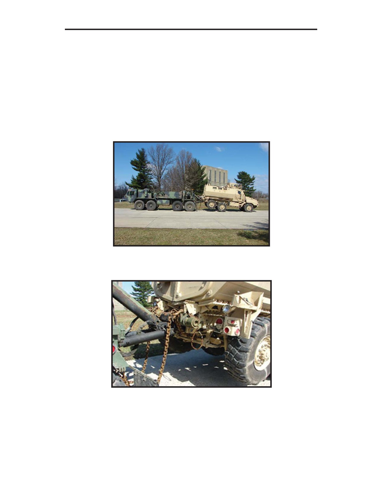
CENTER FOR ARMY LESSONS LEARNED
• Push in the parking brake control on the disabled vehicle.
• Raise the vehicle so the front wheels are 6 to 12 inches above the ground,
depending on terrain.
• Recheck the towing connections, air lines, and chains.
• Tow the disabled vehicle. Use speeds appropriate for conditions, and
avoid sharp turns.
Dedicated recovery, rear tow lift
Figure A-17: HEMTT/MTVR wrecker rear lift tow with MUAs
(NSN 5340-01-516-2058 [L] and NSN 5340-01-516-2059 [R])
Figure A-18: HEMTT/MTVR wrecker rear lift tow with HEMTT BII
adapter F (NSN 2590-01-226-3351 [L] and NSN 2540-01-226-3350 [R])
U.S. UNCLASSIFIED
REL NATO, GCTF, ISAF, MCFI, ABCA
94
For Official Use Only
MRAP VEHICLES HANDBOOK
WARNING
Recovering this vehicle from the rear should be performed only in
emergency combat situations and with the commander’s approval. Decrease
speeds, and be extremely cautious.
Procedures:
Note: To connect the adapters to the tow lugs, the tow pintle must be removed.
•
Straighten and secure the steering wheel before towing.
•
Install the appropriate retrieval system adapters (refer to figures A-17 or
A-18). Using the cylinder controls, lower the cross tube to approximately
3 feet off the ground.
•
Using ground guides, slowly back the recovery vehicle. Connect the
retrieval system MUAs using a 1 in. pin through hole number 2 and
connect to the rear tow lugs of the disabled vehicle.
•
Route chains around the rear axle and connect to the hook on the adapter.
•
Hook safety chains around the rear axle and connect to the rear tow
shackles or the safety chain loop on the wrecker.
•
Leave sufficient slack in the safety chains to allow for turns.
•
Install the tow lights. Check the rigging.
•
Raise the vehicle so the rear wheels are 6 to 12 inches above the ground,
depending on terrain.
•
Recheck the towing connections, air lines, and chains.
•
Tow the disabled vehicle. Use speeds appropriate for conditions, and
avoid sharp turns.
Warnings and Cautions
Warnings:
• If the brakes of the disabled vehicle are inoperable, do not flat tow the
disabled vehicle. Call for wrecker support. Failure to comply may result
in damage to equipment or serious injury or death to personnel.
• When using a wrecker to tow a vehicle with nonfunctional brakes, use
extreme caution and reduce speed accordingly. Failure to comply may
result in damage to equipment or serious injury or death to personnel.
• Do not move the towing vehicle without assistance from a ground guide.
The ground guide must be visible to the operator at all times. Failure to
U.S. UNCLASSIFIED
REL NATO, GCTF, ISAF, MCFI, ABCA
95
For Official Use Only
CENTER FOR ARMY LESSONS LEARNED
comply may result in damage to equipment or serious injury or death to
personnel.
• Do not put hands near the pintle hook when aligning the lunette eye with
the pintle hook. Failure to comply may result in serious injury or death to
personnel.
• When towing, ensure that all personnel are clear of the vehicle before
removing the wheel chocks and starting vehicle towing. Use reasonable
speeds for road conditions and caution when making turns. Prior to
disconnecting the towbar, ensure that the vehicle is on a level surface
with the wheels chocked. Failure to comply may result in damage to
equipment or serious injury or death to personnel.
• The maximum speed limit when towing is 15 mph (24 km/h). Terrain,
weather, and other conditions may require reduced speed; avoid sharp
turns. On paved roads, speed may be increased to 25 mph if conditions
permit. Failure to comply may result in damage to equipment or serious
injury or death to personnel.
Caution: Lift towing of the MRAP vehicle from the rear should be performed only
under emergency conditions and when approved by the commander.
U.S. UNCLASSIFIED
REL NATO, GCTF, ISAF, MCFI, ABCA
96
For Official Use Only

MRAP VEHICLES HANDBOOK
FPI Cougar 4X4 and FPI Cougar 6X6
Figure A-19: FPI Cougar 4X4
Figure A-20: FPI Cougar 6X6
General Information and Equipment Description
Due to the unique design of the FPI Cougar CAT I and CAT II MRAP vehicles,
recovery personnel face several challenges when attempting to recover these
systems. These challenges include size, weight, route clearance, and design issues.
The intent of this section is to provide procedures for recovering disabled vehicles
in emergency situations. These procedures were developed during LFT&E events at
Aberdeen and Yuma Proving Grounds.
IMPORTANT NOTICE
Due to design, towing provisions may differ from vehicle to vehicle. Validate
procedures in training prior to actual recovery missions.
U.S. UNCLASSIFIED
REL NATO, GCTF, ISAF, MCFI, ABCA
97
For Official Use Only

CENTER FOR ARMY LESSONS LEARNED
Vehicle
Crew
Overall
Overall
Overall Height
VCW
GVW
Length
Width
Force
6
233 in.
102 in.
104 in.
32,000 lb.
38,000 lb.
Protection
4X4
130 in. with GPK
Force
8
245 in.
105.5 in.
95 in.
40,000 lb.
52,000 lb.
Protection
6X6
106.5 in. with GPK
Table A-3: Cougar Vehicle Data
Recovery Procedures
Like-vehicle recovery
Like-vehicle towing must be accomplished using a vehicle of equal or greater
weight.
Figure A-21: USMC MTVR towbar (NSN 2350-01-496-8356)
and adapter (NSN 2540-01-500-5325)
U.S. UNCLASSIFIED
REL NATO, GCTF, ISAF, MCFI, ABCA
98
For Official Use Only