Military reference books and manuals (2009-2023, Volume 7) - page 30

MRAP VEHICLES HANDBOOK
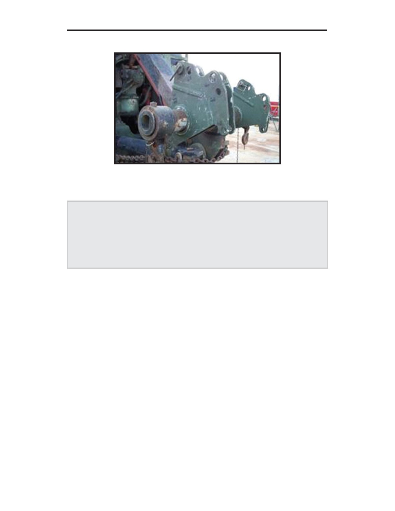
Figure A-22: U.S. Army heavy duty towbar (NSN 2540-01-267-2912)
and adapter (NSN 5340-01-267-2908)
Figure A-23: Cougar modified front tow lug,
1.5 in. thick lug and 1.5 in. pin diameter
Note: If using the MTVR towbar, it must be fully extended.
WARNING
Do not put hands near the pintle hook when aligning the lunette eye with the
pintle hook. Failure to comply may result in serious injury or death to
personnel.
U.S. UNCLASSIFIED
REL NATO, GCTF, ISAF, MCFI, ABCA
99
For Official Use Only
CENTER FOR ARMY LESSONS LEARNED
Towbar connections:
•
Install the towbar (refer to figures A-21 or A-22).
•
Install the air lines, electrical cable(s), safety pins, and safety chains.
Leave sufficient slack in the safety chains to allow for turns.
•
Install the tow lights.
•
Turn the master power switch to the “ON” position. Place the transfer
case in neutral. The drive shaft must be removed if the transfer case will
not shift into neutral.
º The manual neutral override is an alternate method to shift the
transfer case to neutral. The switches are accessible by removing
the cover between the driver and the passenger.
Remove the two Allen-head plugs located on the low/high
cylinder switch and on the neutral shift cylinder switch.
Remove the two 9/16 cage bolts mounted on the low/high
cylinder switch side.
Install one caging bolt in the low/high cylinder switch and
one caging bolt in the neutral cylinder switch and tighten
until the piston bottoms out (do not force or over tighten).
º The neutral switch will indicate neutral engagement.
•
Push in the trailer air supply control on the recovery vehicle. If the air
supply on the casualty vehicle will not hold air, call for wrecker support.
•
Push in the parking brake control on the disabled vehicle.
•
Recheck the towing connections, air lines, and chains.
•
Tow the disabled vehicle. Use speeds appropriate for conditions, and
avoid sharp turns.
Dedicated recovery, front lift tow
Note: If the casualty vehicle has no air pressure, the rear brakes will need to be
caged.
Procedures:
• Install the appropriate retrieval system adapters (refer to figures A-24 or
A-25). Using the cylinder controls, lower the cross tube to approximately
3 feet off the ground.
U.S. UNCLASSIFIED
REL NATO, GCTF, ISAF, MCFI, ABCA
100
For Official Use Only

MRAP VEHICLES HANDBOOK
• Using ground guides, slowly back the recovery vehicle and connect the
retrieval system to the disabled vehicle. If using MUAs, use pin hole
number 4.
• Route the chains around the front axle and connect to the hook on the
adapter.
Figure A-24: HEMTT/MTVR wrecker front lift tow with HEMTT BII
adapter D (NSN 2590-01-226-3349 [L] and NSN 2540-01-226-7139 [R])
Figure A-25: HEMTT/MTVR wrecker front lift tow with MUAs
(NSN 5340-01-516-2058 [L] and NSN 5340-01-516-2059 [R])
U.S. UNCLASSIFIED
REL NATO, GCTF, ISAF, MCFI, ABCA
101
For Official Use Only

CENTER FOR ARMY LESSONS LEARNED
WARNING
Vehicles with catastrophic damage to the front axle and suspension may
require the axle to be properly secured to the chassis for safe recovery of the
vehicle. Never attach safety chains to axles or suspension components that
are no longer physically attached to the vehicle. Never cross the safety
chains.
• Hook the safety chain around the frame or front axle and connect to the
rear tow shackles or the safety chain loop on the wrecker. Ensure there is
sufficient slack in the safety chains to allow for turns.
• Install the air lines, electrical cable(s), and safety pins.
• Install the tow lights. Check the rigging.
• Place the transfer case in neutral. The drive shaft must be removed if the
transfer case will not shift into neutral.
• Push in the trailer air supply control on the recovery vehicle.
• Push in the parking brake control on the disabled vehicle.
• Raise the vehicle so the front wheels are 6 to 12 inches above the ground,
depending on terrain.
• Recheck the towing connections, air lines, and chains.
• Tow the disabled vehicle. Use speeds appropriate for conditions, and
avoid sharp turns.
Dedicated recovery, rear lift tow
Figure A-26: HEMTT/MTVR wrecker rear lift tow with MUAs
(NSN 5340-01-516-2058 [L] and NSN 5340-01-516-2059 [R])
U.S. UNCLASSIFIED
REL NATO, GCTF, ISAF, MCFI, ABCA
102
For Official Use Only

MRAP VEHICLES HANDBOOK
Figure A-27: HEMTT wrecker BII adapter D
(NSN 2590-01-226-3349 [L] and NSN 2540-01-226-7139 [R])
WARNING
Recovering this vehicle from the rear should be performed only in
emergency combat situations and with the commander’s approval. Decrease
speeds and be extremely cautious.
WARNING
Do not use the MTVR wrecker to rear lift tow the FPI CAT I and CAT II;
the vehicle exceeds the retrieval system lift capacity.
Procedures:
• Straighten and secure the steering wheel before towing.
• Install the appropriate retrieval system adapters (refer to figures A-26 or
A-27). Using the cylinder controls, lower the cross tube to approximately
3 feet off the ground.
• Using ground guides, slowly back the recovery vehicle. Connect the
retrieval system MUAs using a 1 1/2 in. pin through hole number 4 and
connect to the rear tow lugs of the disabled vehicle.
• Route the chains around the rear axle and connect to the hook on the
adapter.
• Hook the safety chains around the rear axle and connect to the rear tow
shackles or the safety chain loop on the wrecker.
• Leave sufficient slack in the safety chains to allow for turns.
U.S. UNCLASSIFIED
REL NATO, GCTF, ISAF, MCFI, ABCA
103
For Official Use Only
CENTER FOR ARMY LESSONS LEARNED
• Install the tow lights. Check the rigging.
• Raise the vehicle so the rear wheels are 6 to 12 inches above the ground,
depending on terrain.
• Recheck the towing connections, air lines, and chains.
• Tow the disabled vehicle. Use speeds appropriate for conditions, and
avoid sharp turns.
Warnings and Cautions
Warnings:
•
If the brakes of the disabled vehicle are inoperable, do not flat tow the
disabled vehicle. Call for wrecker support. Failure to comply may result
in damage to equipment or serious injury or death to personnel.
•
When using a wrecker to tow a vehicle with nonfunctional brakes, use
extreme caution and reduce speed accordingly. Failure to comply may
result in damage to equipment or serious injury or death to personnel.
•
Do not move the towing vehicle without assistance from a ground guide.
The ground guide must be visible to the operator at all times. Failure to
comply may result in damage to equipment or serious injury or death to
personnel.
•
Do not put hands near the pintle hook when aligning the lunette eye with
the pintle hook. Failure to comply may result in serious injury or death to
personnel.
•
When towing, ensure that all personnel are clear of the vehicle before
removing the wheel chocks and starting vehicle towing. Use reasonable
speeds for road conditions and caution when making turns. Prior to
disconnecting the towbar, ensure that the vehicle is on a level surface
with the wheels chocked. Failure to comply may result in damage to
equipment or serious injury or death to personnel.
•
The maximum speed limit when towing is 15 mph (24 km/h). Terrain,
weather, and other conditions may require reduced speed; avoid sharp
turns. On paved roads, speed may be increased to 25 mph if conditions
permit. Failure to comply may result in damage to equipment or serious
injury or death to personnel.
Caution: Lift towing of the MRAP vehicle from the rear should be performed only
under emergency conditions and when approved by the commander.
U.S. UNCLASSIFIED
REL NATO, GCTF, ISAF, MCFI, ABCA
104
For Official Use Only

MRAP VEHICLES HANDBOOK
IMG MaxxPro
Figure A-28
General Information and Equipment Description
Due to the unique design of the IMG MaxxPro MRAP vehicle, recovery personnel
face several challenges when attempting to recover these systems. These challenges
include size, weight, route clearance, and design issues.
The intent of this section is to provide procedures for recovering disabled vehicles
in emergency situations. These procedures were developed during LFT&E events at
Aberdeen and Yuma Proving Grounds.
IMPORTANT NOTICE
Due to design, towing provisions may differ from vehicle to vehicle. Validate
procedures in training prior to actual recovery missions.
Vehicle
Crew
Overall
Overall
Overall Height
VCW
GVW
Length
Width
IMG
6
260 in.
120 in.
112 in.
32,000 lb.
41,600 lb.
MaxxPro
159 in. with GPK
Table A-4: IMG Vehicle Data
Recovery Procedures
Like-vehicle recovery
Like-vehicle towing must be accomplished using a vehicle of equal or greater
weight.
U.S. UNCLASSIFIED
REL NATO, GCTF, ISAF, MCFI, ABCA
105
For Official Use Only

CENTER FOR ARMY LESSONS LEARNED
Figure A-29: USMC MTVR towbar (NSN 2350-01-496-8356)
and adapter (NSN 2530-01-520-6538)
Figure A-30: U.S. Army heavy duty towbar (NSN 2540-01-267-2912)
and adapter (NSN 2540-00-863-3153)
WARNING
Do not put hands near the pintle hook when aligning the lunette eye with the
pintle hook. Failure to comply may result in serious injury or death to
personnel.
U.S. UNCLASSIFIED
REL NATO, GCTF, ISAF, MCFI, ABCA
106
For Official Use Only

MRAP VEHICLES HANDBOOK
Figure A-31: HEMTT wrecker flat towing IMG MaxxPro
with USMC MTVR towbar
Note: If using the MTVR towbar, it must be fully extended.
Towbar connections:
• Install the towbar (refer to figures A-29 or A-30).
• Install the air lines, electrical cable(s), safety pins, and safety chains.
Leave sufficient slack in the safety chains to allow for turns.
• Install the tow lights.
• Turn the master power switch to the “ON” position. Place the transfer
case in neutral. The drive shaft must be removed if the transfer case will
not shift into neutral.
• Push in the trailer air supply control on the recovery vehicle. If the air
supply on the casualty vehicle will not hold air, call for wrecker support.
• Push in the parking brake control on the disabled vehicle.
• Recheck the towing connections, air lines, and chains.
• Tow the disabled vehicle. Use speeds appropriate for conditions, and
avoid sharp turns.
Dedicated recovery, front lift tow
Note: If the casualty vehicle has no air pressure, the rear brakes will need to be
caged.
U.S. UNCLASSIFIED
REL NATO, GCTF, ISAF, MCFI, ABCA
107
For Official Use Only

CENTER FOR ARMY LESSONS LEARNED
Figure A-32: HEMTT/MTVR wrecker front lift towing IMG MaxxPro
Procedures:
• Install the appropriate retrieval system adapters (refer to figures A-33 or
A-34). Using cylinder controls, lower the cross tube to approximately 3
feet off the ground.
• Using ground guides, slowly back the recovery vehicle and connect the
retrieval system to the disabled vehicle. If using MUAs, use pin hole
number 2.
• Route the chains around the front axle and connect to the hook on the
adapter.
Figure A-33: HEMTT wrecker BII adapter F (NSN 2590-01-226-3351 [L]
and NSN 2590-01-226-3350 [R])
U.S. UNCLASSIFIED
REL NATO, GCTF, ISAF, MCFI, ABCA
108
For Official Use Only
MRAP VEHICLES HANDBOOK
Figure A-34: HEMTT/MTVR wrecker with MUAs
(NSN 5340-01-516-2058 [L] and NSN 5340-01-516-2059 [R])
WARNING
Vehicles with catastrophic damage to the front axle and suspension may
require the axle to be properly secured to the chassis for safe recovery of the
vehicle. Never attach safety chains to axles or suspension components that
are no longer physically attached to the vehicle. Never cross the safety
chains.
• Hook the safety chain around the frame or front axle and connect to the
rear tow shackles or the safety chain loop on the wrecker. Ensure there is
sufficient slack in the safety chains to allow for turns.
• Install the air lines, electrical cable(s), and safety pins.
• Install the tow lights. Check the rigging.
• Place the transfer case in neutral. The drive shaft must be removed if the
transfer case will not shift into neutral.
• Push in the trailer air supply control on the recovery vehicle.
• Push in the parking brake control on the disabled vehicle.
• Raise the vehicle so the front wheels are 6 to 12 inches above the ground,
depending on terrain.
• Recheck the towing connections, air lines, and chains.
• Tow the disabled vehicle. Use speeds appropriate for conditions, and
avoid sharp turns.
U.S. UNCLASSIFIED
REL NATO, GCTF, ISAF, MCFI, ABCA
109
For Official Use Only

CENTER FOR ARMY LESSONS LEARNED
Dedicated recovery, rear lift tow
Figure A-35: HEMTT/MTVR wrecker rear lift tow with MUAs
(NSN 5340-01-516-2058 [L] and NSN 5340-01-516-2059 [R])
Figure A-36: HEMTT wrecker BII adapter D
(NSN 2590-01-226-3349 [L] and NSN 2540-01-226-7139 [R])
WARNING
Recovering this vehicle from the rear should be performed only in
emergency combat situations and with the commander’s approval. The lack
of rear lift tow provisions requires improvised rigging, which decreases the
stability of the vehicle. Decrease speeds, and be extremely cautious.
U.S. UNCLASSIFIED
REL NATO, GCTF, ISAF, MCFI, ABCA
110
For Official Use Only
MRAP VEHICLES HANDBOOK
WARNING
Do not use the MTVR wrecker to rear lift tow the IMG; the vehicle exceeds
the retrieval system lift capacity.
Procedures:
•
Straighten and secure the steering wheel before towing.
•
Install the appropriate retrieval system adapters (refer to figures A-35 or
A-36). Using the cylinder controls, lower the cross tube to approximately
3 feet off the ground.
•
Using ground guides, slowly back the recovery vehicle. Connect the
retrieval system MUA adapters using 1 1/2 in. pins through hole number
6 and the 3 1/2 in. tie down holes of the disabled vehicle.
•
Route the chains around the rear axle and connect to the hook on the
adapter.
•
Hook safety chains around the rear axle and connect to the rear tow
shackles or the safety chain loop on the wrecker.
•
Leave sufficient slack in the safety chains to allow for turns.
•
Install the tow lights. Check the rigging.
•
Raise the vehicle so the rear wheels are 6 to 12 inches above the ground,
depending on terrain.
•
Recheck the towing connections and chains.
•
Tow the disabled vehicle. Use speeds appropriate for conditions, and
avoid sharp turns.
Warnings and Cautions
Warnings:
• If the brakes of the disabled vehicle are inoperable, do not flat tow the
disabled vehicle. Call for wrecker support. Failure to comply may result
in damage to equipment or serious injury or death to personnel.
• When using a wrecker to tow a vehicle with nonfunctional brakes, use
extreme caution and reduce speed accordingly. Failure to comply may
result in damage to equipment or serious injury or death to personnel.
• Do not move the towing vehicle without assistance from a ground guide.
The ground guide must be visible to the operator at all times. Failure to
comply may result in damage to equipment or serious injury or death to
personnel.
U.S. UNCLASSIFIED
REL NATO, GCTF, ISAF, MCFI, ABCA
111
For Official Use Only
CENTER FOR ARMY LESSONS LEARNED
• Do not put hands near the pintle hook when aligning the lunette eye with
the pintle hook. Failure to comply may result in serious injury or death to
personnel.
• When towing, ensure that all personnel are clear of the vehicle before
removing the wheel chocks and starting vehicle towing. Use reasonable
speed for road conditions and caution when making turns. Prior to
disconnecting the towbar, ensure that the vehicle is on a level surface
with the wheels chocked. Failure to comply may result in damage to
equipment or serious injury or death to personnel.
• The maximum speed limit when towing is 15 mph (24 km/h). Terrain,
weather, and other conditions may require reduced speed; avoid sharp
turns. On paved roads, speed may be increased to 25 mph if conditions
permit. Failure to comply may result in damage to equipment or serious
injury or death to personnel.
Caution: Lift towing of the MRAP vehicle from the rear should be performed only
under emergency conditions and when approved by the commander.
U.S. UNCLASSIFIED
REL NATO, GCTF, ISAF, MCFI, ABCA
112
For Official Use Only

MRAP VEHICLES HANDBOOK
GDLS RG-31
Figure A-37
General Information and Equipment Description
Due to the unique design of the GDLS MRAP vehicle, recovery personnel face
several challenges when attempting to recover these systems. These challenges
include size, weight, route clearance and design issues which may affect recovery
efforts.
The intent of this section is to provide procedures for recovering disabled vehicles
in emergency situations. These procedures were developed during LFT&E events at
Aberdeen and Yuma Proving Grounds.
IMPORTANT NOTICE
Due to design, towing provisions may differ from vehicle to vehicle. Validate
procedures in training prior to actual recovery missions.
Vehicle
Crew
Overall
Overall
Overall Height
VCW
GVW
Length
Width
GDLS
10
268 in.
98 in.
107 in.
26,896 lb.
31,305 lb.
RG31
MK5E
134 in. with GPK
4X4
Table A-5: GDLS Vehicle Data
U.S. UNCLASSIFIED
REL NATO, GCTF, ISAF, MCFI, ABCA
113
For Official Use Only
CENTER FOR ARMY LESSONS LEARNED
Recovery Procedures
Like-vehicle recovery
Like-vehicle towing must be accomplished using towing vehicle of equal or greater
weight than the towed vehicle.
Note: Older vehicle tow lugs have pin holes less than 1 1/2 in. in diameter. Newer
version vehicles are designed with 1 1/2 in. tow lug diameters. If the vehicle front
tow lug diameter is less than 1 1/2 in., use shackle bolt (NSN 4030-01-187-0964) or
use adapter (NSN 2540-00-863-3153), which uses a 1 in. pin.
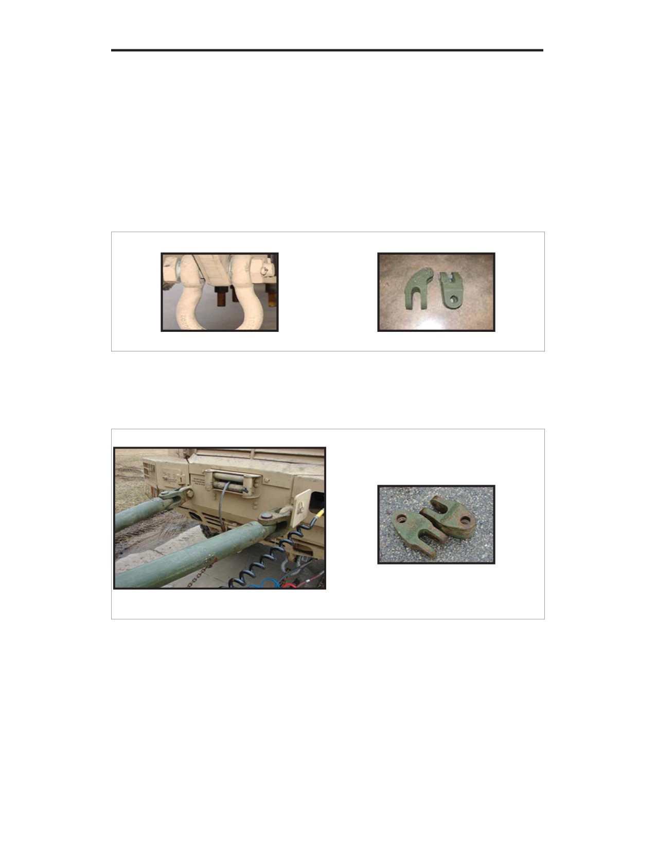
Figure A-38: Shackle bolt (NSN 4030-01-187-0964)
and adapter (NSN 2540-00-863-3153)
Figure A-39: U.S. Army heavy duty tow bar (NSN 2540-01-267-2912)
and adapter (NSN 5340-01-267-2908) and shackle pin
U.S. UNCLASSIFIED
REL NATO, GCTF, ISAF, MCFI, ABCA
114
For Official Use Only

MRAP VEHICLES HANDBOOK
Figure A-40: USMC MTVR tow bar (NSN 2350-01-496-8356)
and adapter (NSN 2540-01-500-5325) and shackle pin
Figure A-41: GDLS connected to a U.S. Army heavy duty tow bar
WARNING
Do not put hands near the pintle hook when aligning the lunette eye with the
pintle hook. Failure to comply may result in serious injury or death to
personnel.
Tow bar connections:
• Install the towbar (refer to figures A-38 or A-41).
• Install the air lines, electrical cable(s) or tow lights, safety pins, and
safety chains. Leave sufficient slack in the safety chains to allow for
turns.
U.S. UNCLASSIFIED
REL NATO, GCTF, ISAF, MCFI, ABCA
115
For Official Use Only

CENTER FOR ARMY LESSONS LEARNED
• Place the transfer case in neutral. The drive shaft must be removed if the
transfer case will not shift into neutral.
• Push in the trailer air supply control on the recovery vehicle. If the air
supply on the casualty vehicle will not hold air, call for wrecker support.
• Lift up and down on the parking brake control level on the disabled
vehicle.
• Recheck the towing connections, air lines, and chains.
• Tow the disabled vehicle. Use speeds appropriate for conditions, and
avoid sharp turns.
Dedicated recovery, front lift tow
Figure A-42: HEMTT wrecker lift towing GDLS
Note: If the casualty vehicle has no air pressure, the rear brakes will need to be
caged.
Procedures:
• Install the appropriate retrieval system adapters (refer to figures A-43 or
A-44). Using the cylinder controls, lower the cross tube to approximately
3 feet off the ground.
• Using ground guides, slowly back the recovery vehicle and connect the
retrieval system to the disabled vehicle. If using MUAs, use 1 1/2 in. pin
hole number 6 or HEMTT BII adapter D or F.
• Route chains around the front axle and connect to the hook on the
appropriate adapter.
U.S. UNCLASSIFIED
REL NATO, GCTF, ISAF, MCFI, ABCA
116
For Official Use Only

MRAP VEHICLES HANDBOOK
Figure A-43: HEMTT/MTVR wrecker front lift tow with HEMTT BII adapter
D or F (NSN 2590-01-226-3349 [L] and NSN 2540-01-226-7139 [R])
Figure A-44: HEMTT/MTVR wrecker front lift tow with MUAs
(NSN 5340-01-516-2058 [L] and NSN 5340-01-516-2059 [R])
WARNING
Vehicles with catastrophic damage to the front axle and suspension may
require the axle to be properly secured to the chassis for safe recovery of the
vehicle. Never attach safety chains to axles or suspension components that
are no longer physically attached to the vehicle. Never cross the safety
chains.
U.S. UNCLASSIFIED
REL NATO, GCTF, ISAF, MCFI, ABCA
117
For Official Use Only
CENTER FOR ARMY LESSONS LEARNED
• Hook the safety chain around the frame or front axle and connect to the
rear tow shackles or the safety chain loop on the wrecker. Ensure
sufficient slack in the safety chains to allow for turns.
• Install the air lines, electrical cable(s) or tow lights, and safety pins.
• Check the rigging.
• Place the transfer case in neutral. The drive shaft must be removed if the
transfer case will not shift into neutral.
• Push in the trailer air supply control on the recovery vehicle.
• Lift up and pull down on the parking brake control level on the disabled
vehicle.
• Raise the vehicle so the front wheels are 6 to 12 inches above the ground,
depending on terrain.
• Recheck the towing connections, air lines, and chains.
• Tow the disabled vehicle. Use speeds appropriate for conditions, and
avoid sharp turns.
Dedicated recovery, rear lift tow
Note: Rear lift tow is not recommend because of interference with adapters and tow
cylinders.
Warnings
• If the brakes of the disabled vehicle are inoperable, do not flat tow the
disabled vehicle. Call for wrecker support. Failure to comply may result
in damage to equipment or serious injury or death to personnel.
• When using a wrecker to tow a vehicle with nonfunctional brakes, use
extreme caution and reduce speed accordingly. Failure to comply may
result in damage to equipment or serious injury or death to personnel.
• Do not move the towing vehicle without assistance from a ground guide.
The ground guide must be visible to the operator at all times. Failure to
comply may result in damage to equipment or serious injury or death to
personnel.
• Do not put hands near the pintle hook when aligning the lunette eye with
the pintle hook. Failure to comply may result in serious injury or death to
personnel.
• When towing, ensure that all personnel are clear of the vehicle before
removing the wheel chocks and starting vehicle towing. Use reasonable
speeds for road conditions and caution when making turns. Prior to
disconnecting the towbar, ensure that the vehicle is on a level surface
U.S. UNCLASSIFIED
REL NATO, GCTF, ISAF, MCFI, ABCA
118
For Official Use Only
MRAP VEHICLES HANDBOOK
with the wheels chocked. Failure to comply may result in damage to
equipment or serious injury or death to personnel.
• The maximum speed limit when towing is 15 miles per hour (mph) (24
kilometers [km] per hour). Terrain, weather, and other conditions may
require reduced speed; avoid sharp turns. On paved roads, speed may be
increased to 25 mph if conditions permit. Failure to comply may result in
damage to equipment or serious injury or death to personnel.
Equipment Data Tables
Max Flat
Model
GCWR
VCW
Under Lift
Tow Weight
M984A2
114,000 lb.
50,900 lb.
63,100 lb.
25,000 lb.
MK 36
98,100 lb.
48,800 lb.
49,300 lb.
14,000 lb.
Table A-6: US Army/USMC Wreckers
Towbar
Towbar NSN
Type
Adapter NSN
Capacity
2350-01-496-8356
MTVR
2540-01-500-5325
83,000 lb.
USMC
Medium duty
7 ton up to 83,000 lb.
5340-01-267-2908
V- type, light,
10-50 ton medium duty
112,000 lb.
2540-01-267-2912
medium, and
M88A1
U.S. Army
heavy duty
2540-00-863-3153
GVW
2 ½-10 ton light duty
Table A-7: Tow Bars and Adapters
U.S. UNCLASSIFIED
REL NATO, GCTF, ISAF, MCFI, ABCA
119
For Official Use Only

CENTER FOR ARMY LESSONS LEARNED
Working
Branch
Chain
Grade
NSN
Load
Limit
Sling, Multiple Leg,
80
3940-01-270-3389
20,300 lb.
16 ft. 5/8 in.
U.S.
Army
Chain Assembly, Single
80
4010-01-249-0548
20,300 lb.
M984A1,
Leg, 14 ft. 5/8 in.
A2
Chain Assembly, Single
40
4010-01-250-5428
5,400 lb.
Leg, 12 ft. 3/8 in.
Chain, Welded, 14 ft.
80
4010-01-516-2095
20,000 lb.
5/8 in.
USMC
MK36
Chain Assembly, Single
40
4010-01-519-2777
5,400 lb.
Leg, 12 ft. 3/8 in.
Table A-8: Chain Working Load Limits
Illustrations
Figure A-45: USMC MTVR tow bar kit (NSN 2350-01-496-8356)
U.S. UNCLASSIFIED
REL NATO, GCTF, ISAF, MCFI, ABCA
120
For Official Use Only

MRAP VEHICLES HANDBOOK
Figure A-46: U.S. Army heavy duty tow bar (NSN 2540-01-267-2912)
Figure A-47: LVS tow bar (NSN 2540-01-183-4497)
U.S. UNCLASSIFIED
REL NATO, GCTF, ISAF, MCFI, ABCA
121
For Official Use Only
CENTER FOR ARMY LESSONS LEARNED
MRAP Flat Tow Recovery
Vehicle
Tow Bars
Tow Bar
Primary Mover
Primary Mover
Primary Mover
Type
Adapters
with Heavy
with MTVR
with LVS
Duty Tow Bar
Tow Bar
Tow Bar
BAE
Heavy Duty Tow
2.5 to 10 ton
HEMTT Wrecker
MTVR Wrecker
LVS Wrecker
Systems
Bar
RG33L
6X6
2540-01-267-2912
2540-00-863-3153
BAE CAT II
48,940 lb.
MTVR
2350-01-496-8356
LVS
2540-01-183-4497
Force
Heavy Duty Tow
10-50 ton
HEMTT Wrecker
MTVR Wrecker
LVS Wrecker
Protection
Bar
Cougar
6X6
2540-01-267-2912
5340-01-267-2908
FPI CAT II
HEMTT Wrecker
HEMTT Wrecker
48,860 lb.
MTVR
7 ton to 83,000 lb.
BAE CAT II
FPI CAT II
FPI CAT II
2350-01-496-8356
2540-01-500-5325
BAE CAT II
LVS
Clevis, rod end
2540-01-183-4497
5340-01-227-3521
BAE-TVS
Heavy Duty Tow
2.5 to 10 ton
HEMTT Wrecker
MTVR Wrecker
LVS Wrecker
Caiman
Bar
6X6
2540-01-267-2912
2540-00-863-3153
BAE-TVS
HEMTT Wrecker
BAE-TVS
46,210 lb.
MTVR
M809/939 to
FPI CAT II
BAE-TVS
FPI CAT II
78,000 lb.
2350-01-496-8356
2530-01-520-6358
BAE CAT II
FPI CAT II
LVS
BAE CAT II
2540-01-183-4497
U.S. UNCLASSIFIED
REL NATO, GCTF, ISAF, MCFI, ABCA
122
For Official Use Only
MRAP VEHICLES HANDBOOK
International
Heavy Duty Tow
2.5 to 10 ton
HEMTT Wrecker
MTVR Wrecker
LVS Wrecker
IMG
Bar
MaxxPro
2540-01-267-2912
2540-00-863-3153
BAE-TVS
HEMTT Wrecker
HEMTT Wrecker
41,600 lb.
MTVR
M809/939 to
FPI CAT II
BAE-TVS
BAE-TVS
78,000 lb.
2350-01-496-8356
2530-01-520-6538
IMG
FPI CAT II
FPI CAT II
LVS
BAE CAT II
IMG
IMG
2540-01-183-4497
BAE CAT II
BAE CAT II
Force
Heavy Duty Tow
10-50 ton
HEMTT Wrecker
MTVR Wrecker
LVS Wrecker
Protection
Bar
Cougar
4X4
2540-01-267-2912
5340-01-267-2908
BAE-TVS
HEMTT Wrecker
HEMTT Wrecker
36,100 lb.
MTVR
7 ton to 83,000 lb.
FPI CAT I
BAE-TVS
BAE-TVS
2350-01-496-8356
2540-01-500-5325
FPI CAT II
FPI CAT I
FPI CAT I
LVS
Clevis, rod end
IMG
FPI CAT II
FPI CAT II
2540-01-183-4497
5340-01-227-3521
BAE CAT I
IMG
IMG
BAE CAT II
BAE CAT I
BAE CAT II
General
Heavy Duty Tow
10-50 ton
HEMTT Wrecker
MTVR Wrecker
LVS Wrecker
Dynamics
Bar
RG31E
2540-01-267-2912
5340-01-267-2908
BAE-TVS
HEMTT Wrecker
HEMTT Wrecker
35,640 lb.
MTVR
7 ton to 83,000 lb.
FPI CAT I
BAE-TVS
BAE-TVS
2350-01-496-8356
2540-01-500-5325
FPI CAT II
FPI CAT I
FPI CAT I
LVS
Clevis, rod end
GDLS
FPI CAT II
FPI CAT II
2540-01-183-4497
5340-01-227-3521
IMG
GDLS
GDLS
BAE CAT I
IMG
IMG
BAE CAT II
BAE CAT I
BAE CAT I
BAE CAT II
BAE CAT II
U.S. UNCLASSIFIED
REL NATO, GCTF, ISAF, MCFI, ABCA
123
For Official Use Only
CENTER FOR ARMY LESSONS LEARNED
References
Field Manual (FM) 4-30.31, Recovery and Battle Damage Assessment and Repair
FM 21-305, Manual for the Wheeled Vehicle Driver
Technical Bulletin 9-2320-279-12-1, Operator Maintenance Component of End
Item (COEI) for MUA parts
Training Circular 43-35, Recovery and Training
Technical Manual (TM) 9-2320-279-10-1, M977 Series, 8x8 Heavy Expanded
Mobility Tactical Trucks HEMTT
TM 9-2320-279-10-2, M977 Series, 8x8 Heavy Expanded Mobility Tactical Trucks
HEMTT
TM 9-2355-106-10, Operator Manual Commercial Off-the-Shelf (COTS) for
International Mine Resistant Vehicle
TM 9-2355-107-10, BAE-TVS Caiman Mine Resistant Vehicle, Operator Manual
COTS
TM 9-2355-108-10, BAE RG33 and RG33L Operator Manual COTS
TM 10001620, Force Protection Industries, Inc. MRAP 4x4
TM 10001625, Force Protection Industries, Inc. MRAP 6x6
TM 10633A-10A, Truck, Wrecker, 7-Ton, MK 36
TM 10867B-12&P, Operator Manual for Medium Duty Towbar Kit (USMC)
U.S. UNCLASSIFIED
REL NATO, GCTF, ISAF, MCFI, ABCA
124
For Official Use Only
MRAP VEHICLES HANDBOOK
Appendix B-1
Rollover/Egress Procedures
The following information is taken from GTA 07-09-001: Mine Resistant Ambush
Protected (MRAP) Family of Vehicles Emergency Rollover/Egress Procedures
(proponent: U.S. Army Infantry School, Fort Benning, GA, May 2008).
Road Rollover/Egress Emergency Procedures
WARNING
Never attempt to leap from a rolling vehicle. It may roll over you. Ensure
that the vehicle has stopped its roll before moving. Upon complete
evacuation of all personnel, vehicle should be inspected for fire hazards such
as leaking oil, fuel, and hydraulic fluid. Use the portable fire extinguisher
when inspecting vehicle for leaks in case of fire, which could cause injury or
death. If hazardous/explosive materials are involved, driver should take
actions according to the DD Form 836 accompanying load. Notify
emergency response personnel and remain at a safe evacuation distance (as
determined by the commander on the ground) while securing accident site.
WARNING
Operating on single-lane and or steeply crowned rural roads, roads with no
shoulders, roads with soft shoulders, and/or washouts around culverts, and
especially any road bordering water (canal irrigation ditch/ponds) requires
extreme caution. The majority of MRAP vehicle rollovers are due to the
road/shoulder/bridge approach giving way under the MRAP vehicle’s
weight and high center of gravity.
Preventive measures:
• Wear seatbelts. Survive the rollover!
• Watch for soft soil on shoulders. Soft shoulders are prevalent after rain.
When an MRAP vehicle goes off a road, it can overturn when it strikes a
ditch or embankment or is tripped by soft soil. If you drive off the
roadway, gradually reduce speed. Ease your vehicle back onto the
roadway at a safe speed.
• Slow down. As the MRAP vehicle’s speed increases, the centrifugal
force or sideways force increases. Faster speeds also result in decreased
driver response times. When maneuvering through curves or sudden
traffic situations, an MRAP vehicle with a high center of gravity can
easily turn over. Watch out for sharp curves or steep slopes (greater than
50 percent up/down slope and 30 percent side slope) that generate
centrifugal forces, increasing the chance of rollover.
U.S. UNCLASSIFIED
REL NATO, GCTF, ISAF, MCFI, ABCA
125
For Official Use Only
CENTER FOR ARMY LESSONS LEARNED
• Avoid panic. Many rollovers occur when the driver panics and jerks the
steering wheel during an emergency. Jerking the steering wheel can cause
loss of vehicle control.
• Keep the vehicle center of gravity low. The height of a vehicle’s center
of gravity and the length of the wheelbase determine the vehicle’s
stability. Load and secure heavier items low in the MRAP vehicle.
• Load security. All equipment inside the MRAP vehicle must be secured
in accordance with the vehicle’s and/or unit’s load plan. Unsecured loads
can become deadly projectiles. Improperly secured loads can change a
vehicle’s center of gravity and its stability.
• Condition and prepare vehicle. It is critical that the MRAP vehicle is in
good operating condition before starting your mission. Pay particular
attention to tire condition and air pressure. Worn and improperly inflated
tires increase risk of rollover. Properly performed preventive maintenance
checks and services is the best way to control this potential hazard.
Key points:
• Egress rehearsal. Rehearse vehicle evacuation as if only one exit is
available.
• Communication with the driver. Work as a team and inform the driver
of hazards such as road obstacles, pot holes, and soft shoulder roads. The
gunner is often in a good position to alert the driver of potential road
hazards. Use a ground guide whenever possible due to the vehicle’s
restricted visibility.
• Combat door locks. They are designed to keep the enemy out. When
locked, they also make it extremely difficult for rescuers to enter the
vehicle!
• Locking doors. Combat locks help keep the doors closed during an
accident or combat action. Leaders must decide (based on the enemy
situation) whether or not to keep the doors locked when operating near
bodies of water. Know the locations of your combat door lock keys in
each MRAP vehicle. If you have other types of MRAP vehicles in your
patrol, have combat door lock keys for those as well.
Work as a team
There are multiple hatch locations, types, and operational configurations within the
MRAP family of vehicles. Ensure all personnel fully understand the associated
vehicle’s egress points and operation and constantly rehearse egress drills as a
team. Check your operator’s manual for specific procedures for the various
configurations and mission loads.
Communicate with the driver — tell the driver what is to the left, right rear, and
overhead. Your gunner is your eyes and ears. The gunner may be the only crew
member capable of seeing around the entire vehicle. Know your MRAP’s dead
space/blind spots. Overwatch and cover each other’s dead space/blind spots.
U.S. UNCLASSIFIED
REL NATO, GCTF, ISAF, MCFI, ABCA
126
For Official Use Only
MRAP VEHICLES HANDBOOK
Use the vehicle intercom system to pass visual information to the driver, but
rehearse shouted voice commands and hand signals in case the intercom is
inoperative.
Avoid hazards; use a ground guide whenever possible.
Rollover drill task steps and performance measures
All personnel in a seat or position with restraints will wear them!
1. Execute rollover drill:
•
Driver:
º Releases the accelerator.
º Steers into direction of the roll.
º Yells “Rollover, Rollover, Rollover!”
º Keeps his hands on the steering wheel with extended and
unlocked arms, tucks head and chin into chest, and braces for
impact.
•
Vehicle commander:
º Yells “Rollover, Rollover, Rollover!”
º Pulls gunner into cab (if applicable/able).
º Tucks head and chin into chest and braces for impact.
º Plants feet firmly on the floor while holding onto stationary
object.
•
Gunner (if applicable):
º Yells “Rollover, Rollover, Rollover!”
º Drops down from the hatch into the vehicle.
º Tucks head and chin and braces for impact while holding onto
stationary object.
•
Rear occupants or passengers:
º Yell “Rollover, Rollover, Rollover!”
º Pull gunner into cab (if applicable/able).
º Tuck heads and chins into chest and brace for impact.
U.S. UNCLASSIFIED
REL NATO, GCTF, ISAF, MCFI, ABCA
127
For Official Use Only
CENTER FOR ARMY LESSONS LEARNED
º Plant feet firmly on the floor while holding onto stationary object.
2. After the rollover has stopped:
• Driver shuts down engine.
• Crew disconnects headsets.
• Crew releases seatbelts/restraints; uses caution if upside down.
• Crew unlocks combat door looks (if applicable). Exits vehicle.
• Assess injuries. (Address potential for post crash fire — if applicable.)
• Assist other personnel to exit and secure weapons.
• Establish security.
• Account for personnel.
• Provide first aid.
• Account for weapons, ammunition, and sensitive items.
• Assist in vehicle recovery.
• Report mishap to higher headquarters and request help and/or recovery as
required.
Water Rollover/Egress Emergency Procedures
WARNING
Combat door locks on the MRAP family of vehicles keep the enemy out. When
locked, they make it extremely difficult for rescuers to enter the vehicle.
Commanders should determine when combat locks should be used when conducting
operations near bodies of water. Combat/accident damage may also jam doors,
making them impossible to open. If the doors cannot be opened and the vehicle is in
water too deep to allow air in the vehicle, the likelihood of drowning is high. In this
case, rescuers must immediately roll the vehicle on its side using all available means
(tow straps, rope, winch cables, etc.) to gain access to the gunner’s cupola Identify
non-swimmers and assign them a buddy that is a swimmer. The body of water may
be deep enough that you must swim to shore.
Preventive measures
When in the vicinity of water and tactical conditions permit:
• Reduce speed and stop vehicle.
U.S. UNCLASSIFIED
REL NATO, GCTF, ISAF, MCFI, ABCA
128
For Official Use Only
MRAP VEHICLES HANDBOOK
• Inform all personnel that you are operating around potential water
hazards.
• Conduct a risk assessment of the terrain and route before proceeding.
• Maintain secure seating position by wearing seatbelts.
• Unlock combat door locks, if enemy situation permits.
• Turn on filtered dome lights.
Rollover drill task steps and performance measures
All personnel in a seat or position with restraints will wear them!
1. Execute water egress drill: (when water entry is imminent)
•
Driver:
º Releases the accelerator.
º Steers vehicle to control entry into water and to prevent rollover.
º Yells “Water, Water, Water!”
º Keeps his hands on the steering wheel with extended and
unlocked arms, tucks head and chin into chest, and braces for
impact.
•
Vehicle commander:
º Yells “Water, Water, Water!”
º Pulls gunner into cab (if applicable/able).
º Tucks head and chin into chest and braces for impact.
º Plants feet firmly on the floor while holding onto stationary
object.
•
Gunner (if applicable):
º Yells “Water, Water, Water!”
º Drops down from the hatch into the vehicle.
º Tucks head and chin and braces for impact while holding onto
stationary object.
U.S. UNCLASSIFIED
REL NATO, GCTF, ISAF, MCFI, ABCA
129
For Official Use Only
CENTER FOR ARMY LESSONS LEARNED
•
Crew:
º Yell “Water, Water, Water!”
º Pull gunner into cab (if applicable/able).
º Tuck heads and chins into chest and braces for impact.
º Plant feet firmly on the floor while holding onto stationary object.
2. When the vehicle is stabilized:
•
Driver shuts down engine.
•
Crew disconnects headsets.
•
Crew releases seatbelts/restraints; uses caution if upside down.
•
Crew unlocks combat door locks (if applicable). Exits vehicle.
•
Assess injuries.
•
Assist other personnel to exit and secure weapons.
•
Decide whether to remove load bearing equipment, body armor, and
helmet.
•
Get to safest shore.
•
Establish security.
•
Account for personnel.
•
Provide first aid.
•
Account for weapons, ammunition, and sensitive items.
•
Assist in vehicle recovery.
•
Report mishap to higher headquarters, and request help and/or recovery
as required.
Water Rescue/Recovery
Water rescue drill task steps and performance procedures:
• Secure the accident site.
• Stay in contact with the vehicle, hold onto the vehicle, and kick/swim to
high point in buddy teams.
• Rescuers tie a rope/cable to the vehicle to aid in rescue.
U.S. UNCLASSIFIED
REL NATO, GCTF, ISAF, MCFI, ABCA
130
For Official Use Only
MRAP VEHICLES HANDBOOK
• Open doors and hatches.
• If door and hatches are not accessible, rescuers must immediately use all
available means to turn the vehicle on its side to gain access to the
gunner’s cupola.
• Seek out the highest point on/in the vehicle.
• Ensure that all survivors have air and are able to breathe.
• Check for other injuries and apply first aid.
• Carefully move injured personnel to the highest point on the vehicle.
• Remove excess equipment, to include body armor, in deep water.
• Evacuate from vehicle high point to safest location, depending on:
º Enemy situation
º Water level and flow
º Water temperature
º Distance to water’s edge
º Anticipation of rescue
MEDEVAC Request
Line 1: 6-digit unit training management (UTM) grid location of pickup site
Line 2: Radio frequency, call sign, and suffix of requesting personnel
Line 3: Number of patients by precedence: Urgent, Urgent-Surgery, Priority,
Routine, and Convenience
A - Urgent (loss of life or limb within 2 hours)
B - Urgent Surgical (surgery required)
C - Priority (loss of life or limb within 4 hours)
D - Routine (evacuation within 24 hours)
E - Convenience (as assets are available)
Line 4: Special equipment required, as applicable: none, hoist, or stokes litter
Line 5: Number of patients by type: litter or ambulatory
Line 6: Security of pick-up site: determine possible or known threat in the area
U.S. UNCLASSIFIED
REL NATO, GCTF, ISAF, MCFI, ABCA
131
For Official Use Only
CENTER FOR ARMY LESSONS LEARNED
Line 7: Method of marking pickup site: near, far, recognition devices
Line 8: Patient nationality and status: coalition military, U.S. contractor, enemy
prisoner of war, etc.
Line 9: Terrain description
Report the Accident
An accident report is required by all service safety regulations. This report is
different from the significant incident or activities reports which go through
operations channels and should include the following:
• Who: Unit, individuals
• What: Accident or combat, date and time
• Where: 6-digit UTM grid
• How: What caused the rollover? Speed? Visibility? What was the cause
of injury or death?
• Follow up initial report with information regarding:
º Weather conditions
º Were occupants wearing seatbelts?
º Was fatigue a factor? Did occupants sleep prior to incident?
º Was the driver able to see the hazard/other vehicle?
º Was personal protective equipment (advanced combat helmet,
body armor) worn by each occupant?
º What was the level of operator training, experience, and license?
• Complete appropriate service mishap report and forward to higher
headquarters safety channels.
U.S. UNCLASSIFIED
REL NATO, GCTF, ISAF, MCFI, ABCA
132
For Official Use Only
MRAP VEHICLES HANDBOOK
Appendix B-2
Surviving Contact with High-Voltage Power Lines
Accidental contact (or close proximity) between a mine-resistant ambush-protected
(MRAP) vehicle (especially its radio antennae) and high-voltage power lines can
result in severe injury or death to vehicle occupants. The current (amperes) is the
killing factor in electrical shock: at over four amps, tissue begins to burn, heart
muscles clamp, and the heart stops beating. These events occur as a person’s body
provides a path for current flow (called gradient voltage/step potential and indicated
by a tingling sensation felt in the feet), causing tissue damage and heart failure.
Other injuries may include burns from the arc generated by accidental contact or
close proximity.
When an energized line makes contact or arcs through the air from the power line
through the MRAP vehicle to the ground, the earth becomes hot and the voltage
dissipates in concentric rings away from the initial contact point. The power in the
gradient voltage rings will vary based on soil composition and moisture content;
there is no reliable way to tell how far the gradient voltage rings will emanate from
the vehicle. Studies indicate gradient voltage extends from 10 meters in dry soil and
up to 40 meters in wet soil.
Always keep in mind the following safety information:
• Always watch for overhead hazards like power lines, especially
high-voltage lines.
• Always assume that overhead power lines have no have protective
insulation, so any contact is dangerous.
• Work as a team: Soldiers should be on the lookout for possible contact
between equipment and power lines.
• Nonmetallic materials can conduct electricity. These matrials include
lumber, tree limbs, tires, and ropes.
• Electricity seeks one or multiple paths of least resistance, including
passing through a person.
• Do not touch power lines.
• Stay away from fallen overhead wires. Report downed lines as a hazard to
other units operating in the area.
• Plan a route using the most current trafficability and hazards map of the
area of operations, if mission allows; avoid overhead power lines.
If the MRAP vehicle contacts a live power line (if tactical conditions allow):
• Stay in the vehicle until lines are disengaged or de-energized. Do not try
to get out unless the vehicle is on fire.
U.S. UNCLASSIFIED
REL NATO, GCTF, ISAF, MCFI, ABCA
133
For Official Use Only
CENTER FOR ARMY LESSONS LEARNED
• If able, disconnect from the power line. Back the vehicle away from the
power line.
• A second vehicle should take steps to render the power lines safe. Get
help from the power company (if possible). Make sure no one else
approaches the vehicle.
• Do not leave the vehicle until the line is de-energized.
If the vehicle catches on fire, exit the vehicle carefully:
• Jump out of the vehicle. Do not worry about how far you jump, as long as
you clear the vehicle.
• Be sure to land on both feet and keep your balance when you land. This
factor is more important than how far away you jump.
• Do not touch anything with your hands (wires, vehicle, vegetation); use
your hands for balance only.
• Keep both feet on the ground at all times. Hop away from the vehicle —
be sure to keep both feet together. Keeping the feet together reduces the
differences of gradients of voltage; use your hands for balance only.
• If you cannot hop, shuffle away (heel-to-toe) — and keep both feet on the
ground at all times. Do not lift one foot off the ground to step forward.
Instead, drag one foot forward keeping it in touch with the ground.
• Keep hopping or shuffling away until you get to where other people are
standing safely or you do not have tingling in your feet.
• Do your 5-25-200 meter improvised explosive device-defeat checks, and
set up security/cordon. Call for assistance.
Electrical Accidents
Rescue may pose as great a hazard for the rescuer as for the victim. Victims may be
unable to move. Victims may be held to the circuit by muscles that have contracted.
Victims must be rescued as soon as possible to survive. What action will you take
when you find an electrical accident victim? Who will you call first? What tools or
protective equipment will you need? What are your primary safety considerations?
What will your first response be?
Electrical accident rescue techniques:
• Approach the accident scene cautiously. Never rush into an accident
situation.
• Report the incident to higher as soon as possible.
• Get the aid of trained electrical personnel if possible.
• Examine the scene:
U.S. UNCLASSIFIED
REL NATO, GCTF, ISAF, MCFI, ABCA
134
For Official Use Only
MRAP VEHICLES HANDBOOK
º Visually examine the victims to determine if they are in contact
with energized conductors (metal surfaces, objects near the
victim, or the earth itself may be energized).
º Do not touch the victim or conductive surfaces while they are
energized.
º De-energize electrical circuits if possible — open a disconnecting
device or circuit breaker to de-energize the fixed electrical
equipment.
º Be alert for hazards such as stored energy, heated surfaces, and
fire.
• If you cannot de-energize the power source, use extreme care:
º Ensure that your hands and feet are dry.
º Wear protective equipment such as low-voltage gloves and
overshoes if available.
º Stand on a clean dry surface if possible.
º Use nonconductive material (shepherd’s hook) to remove a victim
from the conductor.
High-voltage rescue
Special training is required for rescues if high voltage is present:
• Wear protective equipment such as high-voltage gloves and overshoes.
• Use special insulated tools.
º Use devices such as hot sticks or shotgun sticks to remove a
victim from energized conductors.
º In some cases, nonconductive rope or cord may be used to remove
a victim from a conductor.
• Rescuing the victim:
º Stand on a dry rubber blanket or other insulating material if
possible.
º Do not touch the victim or conductive material near the victim
until the power is off.
º Once power is off, examine the victim to determine if he should
be moved.
º Give first aid:
U.S. UNCLASSIFIED
REL NATO, GCTF, ISAF, MCFI, ABCA
135
For Official Use Only
CENTER FOR ARMY LESSONS LEARNED
A victim may require cardio-pulmonary resuscitation.
If the victim is breathing and has a heartbeat, give first aid
for injuries and treat for shock.
Ensure the victim gets medical care as soon as possible.
Provide medical personnel with information on voltage
level, shock duration, and entry/exit points. The
treating/attending physician must have detailed specific
information to properly diagnose and care for the victim.
Stay with the victim until help arrives.
Suggested equipment for electrical safety:
• Rubber gloves, 3,000 volts, sizes 9-12 (NSN 8415-01-158-449/9540/
9451/9452)
•
25 ft. rope (NSN 4020-00-174-3031)
• Grounding stick
• Shepherd’s hook
Electrical Arcs
(Note: The following information is extracted from the “Study Guide, Electrical
Safety Hazards Awareness” provided by the Arizona Public Service Company.)
The current in high-voltage power lines can jump an air gap (depending on line
voltage up to 13 feet) to the ground. Depending on a combination of atmospheric
conditions—humidity, suspended particulate matter, and proximity of vehicle to the
power line—a lightening-like arc will form between the vehicle (antennae) and the
ground. If the vehicle continues to move away from the power line, the arc will
cease. Damage can still occur that may disable the vehicle by blowing tires, setting
off electrically primed ammunition, or causing other electrical malfunctions that
may stop the vehicle within the arc-air gap distance, and current will continue to
flow. This situation leads to the explosive effects known as electrical arc blasts.
In addition to an electrical shock and burns, another hazard to Soldiers is the blast
effect that can result from arcing. If the current involved is great enough, these arcs
can cause injury and start fires, explode tires, and set off electrically primed
ordnance.
U.S. UNCLASSIFIED
REL NATO, GCTF, ISAF, MCFI, ABCA
136
For Official Use Only

MRAP VEHICLES HANDBOOK
Figure B-2
Extremely high-energy arcs can damage equipment, causing fragmented metal to
fly in all directions. Low-energy arcs can cause violent explosions or blasts in
atmospheres containing explosive gases, vapors, or combustible dusts. The hot
vaporized metal from the arc blast will combine with oxygen and become an oxide
of the metal of the arc. These molten particles will stick to almost anything and
actually melt into many surfaces. Clothing may ignite as a result of contact with
this molten material, and a victim may receive serious burns. Also, your body has
an instinctive reaction when you are suddenly startled to breathe in heavy or to
gasp. Inhaling the hot vaporized particles will cause serious damage to your
respiratory system by burning the lungs, throat, and esophagus.
The effects of an arcing fault, as seen in Figure B-2, can be devastating to an
individual. The intense thermal energy released in a fraction of a second can cause
severe burns. Molten metal is blown out and can burn skin or ignite flammable
clothing. One of the major causes of serious burns and deaths to individuals is the
ignition of flammable clothing due to an arcing fault. The tremendous pressure blast
from the vaporization of conducting materials and superheating of air can fracture
ribs, collapse lungs, and knock individuals off ladders or blow them across a room.
U.S. UNCLASSIFIED
REL NATO, GCTF, ISAF, MCFI, ABCA
137
For Official Use Only
MRAP VEHICLES HANDBOOK
Appendix B-3
Necessary Precautions During Battlefield Vehicle Crew Rescue,
Recovery, and Forensic Collection Efforts
In the event of a vehicle fire or combat damage, hazardous substances that require
the use of protective measures remain in the vehicle/incident area. This appendix
addresses protective measures needed to ensure that a safe and healthful
environment is available for security, recovery, and forensic/investigation
personnel.
Military vehicles are composed of advanced composite materials such as graphite,
epoxies, plastics, Kevlar, wire insulation, and fiberglass. When a fire occurs during
an accident or combat, fragmented composites, long-chain hydrocarbons, burned
organic materials, and gases are generated. These composites include but are not
limited to carbon monoxide, nitric oxides, sulfur dioxides, and hydrogen cyanide,
as well as burned carbon/Kevlar/fiberglass fibers.
During rescue and recovery operations, biological hazards involving blood-borne
pathogens may be present as well.
All of these substances pose potential health hazards to anyone close to or inside
the combat damaged /burned-out vehicle. In the event of combat damage (with or
without fire), be aware of sharp metal edges, sharp fragments, unexploded
ordnance, and pulverized glass from ballistic windows (see section on ballistic glass
on page 142).
Local emergency agencies serving an operational environment will most likely
accomplish the fire fighting operations. The senior military person present assumes
control of the area and ensures the following precautions are taken:
• Follow standing operating procedures (SOPs) to secure the area and
accomplish the 5-25 checks. Minimize access for nonessential personnel
to the site. Allow only rescue personnel to enter the immediate area until
deemed safe.
• Set up a perimeter and restrict all unprotected personnel from assembling
downwind of the wreckage. Cordon off the area and restrict entry to a
single entry/exit point. In addition, restrict access to the immediate area
where burnt composite fibers have been stirred or are currently being
examined.
• If live munitions or explosives are involved, personnel will be restricted
except those essential to effect immediate life-saving efforts. All other
personnel will be restricted from entering the area until it has been
cleared by the explosive ordnance disposal teams.
• Restrict recovery and investigative personnel from entering the site until
they are equipped to prevent their exposure to body fluids, blood-borne
pathogens, hazardous material, or airborne contaminants.
U.S. UNCLASSIFIED
REL NATO, GCTF, ISAF, MCFI, ABCA
139
For Official Use Only
CENTER FOR ARMY LESSONS LEARNED
Personal Protection Equipment
Personnel required to access the wreckage site will be equipped and use personal
protection equipment (PPE). This equipment will consist of a pair of heavy leather
work gloves and the M40 protective mask (or in permissive environments an N-95
respirator for dust/particulate hazards) to provide adequate protection from airborne
contaminates and fibers. A permissive environment constitutes a threat condition
where maintenance/recovery operations may proceed, and access to guidance from
an on-scene safety and health professional can provide definitive recommendations
for respiratory protective equipment. All items of PPE will be worn when moving,
handling, breaking, or ripping apart composite fiber components. Additional PPE
will be used as appropriate.
Anyone handling compromised components will be equipped with and use an M40
protective mask (or when in permissive environments an N-95 respirator is
adequate for dust/particulate hazards), eye protection, and leather gloves. All
personnel involved should shower prior to going off duty or changing into a
different set of clothing to help prevent the spread of airborne fibers and/or
pulverized glass from the ballistic windows.
Transporting and Storing Damaged/Destroyed Vehicles
Storage of the damaged/destroyed vehicle will be at the discretion of the
commander or SOP. Transportation requirements for recovering a fire-damaged/
destroyed vehicle will be in accordance with the unit recovery SOP. The SOP
should include the following measures to deal with the hazardous environment
following a vehicle fire:
• The wreckage will be cordoned off and remain off limits to all personnel
unless they are part of the accident investigation team or assigned to
assist in recovery.
• The area will be cleared of all nonessential personnel prior to the
wreckage entering the storage area.
• Essential personnel will wear a N95 respirator, safety eyeglasses with
side shield, and leather gloves to prevent airborne contaminants and/or
pulverized glass from entering the body.
A list of safety equipment is shown below:
U.S. UNCLASSIFIED
REL NATO, GCTF, ISAF, MCFI, ABCA
140
For Official Use Only
MRAP VEHICLES HANDBOOK
Item
NSN
X-Small:
Leather Gloves
8415-01-394-0208
Small:
8415-01-394-0209
Medium:
8415-01-394-0210
Large:
8415-01-394-0215
X-Large:
8415-01-397-3937
Rubber Gloves
Size 8: 415-01-463-5927
Size 9: 415-01-463-5934
Size 10: 415-01-463-5928
Latex Gloves
8415-01-434-1781
Safety Goggles/Glasses
4240-01-292-2818
Dust Mask, High-Efficiency
Respirators (N95 or better) (not for use
4240-01-463-5449
near metal fires or organic material
[paints, plastics, or composites] fires)
M40 Protective Gas Mask (Respirator)
4240-01-370-3822
Biohazard Bags
8105-01-148-0280
Garbage Bags
Light Duty 10 Gal: 8105-01-175-5533
Light Duty: 37 Gal: 8105-00-579-8451
Heavy Duty 25 Gal: 8105-01-183-9767
Heavy Duty 59 Gal: 8105-01-221-3239
Bundle Ties
8135-00-846-8409
Footlocker
5140-00-226-9019
Coveralls, TYVEK
Small: 8415-00-L01-6122
Med: 8415-00-L01-6123
Large: 8415-00-L01-6124
Coveralls, TYVEK
XLarge: 8415-00-L01-6125
2XLarge: 8415-00-L01-6126
3XLarge: 8415-00-L01-6127
4XLarge: 8415-00-L01-6128
5XLarge: 8415-00-L01-6129
Table B-3
U.S. UNCLASSIFIED
REL NATO, GCTF, ISAF, MCFI, ABCA
141
For Official Use Only

CENTER FOR ARMY LESSONS LEARNED
Ballistic Glass
(Note: The following information on the ballistic glass used in MRAP vehicles is
taken from <http://www.autosafety.com/Ballistic%20Glass.htm>.)
The figure below shows a multilayer “sandwich,” with the glass facing outside and
the poly as the inner surface. As the projectile proceeds, the different layers act like
a catcher’s mitt in slowing down the round and then physically catching it in one of
the layers. This is why B4 glass is typically 21-24-mm thick and B6 is 41-44-mm.
Figure B-3
Legend:
1. Glass with ceramic frit: This is the outer sheet of glass that looks very much
like the original equipment glass in both shape and size.
2. PVB: This is the adhesive inner layer between sheets of glass.
3. Glass: Second sheet of glass.
4. PVB: This is the adhesive inner layer between sheets of glass.
5. Glass: Third sheet of glass.
6. PVB: This is the adhesive inner layer between sheets of glass.
7. Glass: Fourth and last sheet of glass. It is cut smaller and forms the channels that
will interlock with a similar mating hard armor frame surrounding the door.
8. Polyurethane: This is the adhesive inner layer between glass and the
polycarbonate, which acts as an anti-spall shield.
9. Polycarbonate with abrasive resistant coating: The polycarbonate acts as an
anti-spall shield.
U.S. UNCLASSIFIED
REL NATO, GCTF, ISAF, MCFI, ABCA
142
For Official Use Only
MRAP VEHICLES HANDBOOK
Appendix C
Warnings and Cautions Common to the
Mine-Resistant Ambush-Protected Vehicle
The following warning messages from TM 9-2355-106-10, Operator Manual
Commercial Off-the-Shelf (COTS) for International Mine Resistant Vehicle,
provide information that can help prevent serious injury (loss of limb, hearing, or
eyesight; burns; respiratory problems) or death to personnel, damage to vehicle
components, or both.
Chemical Agent Resistant Coating
Vehicles are finished with a chemical agent resistant coating (CARC):
•
CARC contains isocyanates, which are highly irritating to the skin and
the respiratory system.
•
Breathing of vapor or dried paint dust can cause cough, shortness of
breath, a burning sensation in the throat and nose, watering of the eyes,
pain during respiration, and chest tightness.
•
Skin contact with particulates can cause itching or redness of the skin.
•
Only qualified painters working in fully equipped facilities in protective
gear and respirators should perform CARC painting operations.
•
Never weld or cut CARC-coated surfaces.
•
Grinding or sanding on CARC-coated surfaces will create harmful dust.
All individuals in the area must wear high-efficiency air purifying
respirators, protective goggles, gloves, and other protective clothing.
Thoroughly wash all clothing before reuse.
•
No persons who have lung or breathing problems or who have had a
reaction to isocyanates should be in the area where isocyanates are used
or where CARC dust particles are present. Individuals who are sensitive
to isocyanates may experience increasing sensitivity on repeated
exposure.
Maintenance
General items:
• When using compressed air for cleaning purposes, do not exceed 30 psi
(207 kPa). Wear gloves and eye protection. Do not aim compressed air at
yourself or other people.
• Remove all jewelry before conducting maintenance. Do not wear
watches, rings, dog tags, or other jewelry that could short across battery
terminals or catch on vehicle components.
U.S. UNCLASSIFIED
REL NATO, GCTF, ISAF, MCFI, ABCA
143
For Official Use Only
CENTER FOR ARMY LESSONS LEARNED
•
Always maintain three points of contact when climbing on the vehicle.
Never jump from the vehicle. Use ladders during maintenance as
applicable.
•
Ensure cargo is stowed and secured in accordance with the load plan. Do
not block fire sensors or extinguisher nozzles. Do not block egress paths.
•
Do not exceed the rated payload of the vehicle.
•
In extreme temperature environments, follow work-rest schedules as well
as the guidance of TB-MED 507, Heat Stress Control and Heat Stress
Management, and TB-MED 508, Prevention and Management of Cold
Weather Injuries.
•
Antennas emit radio frequency radiation. Do not touch an active antenna,
and maintain proper standoff distances from an active antenna as
specified in the radio equipment technical manual. Ensure radios are
powered off before conducting fueling operations or maintenance
activities.
•
Rotating parts can cause severe injury to personnel. Ensure all guards are
in place. Do not wear loose clothing when conducting maintenance.
Always check to ensure area is clear of personnel and obstructions before
starting the engine.
•
Single hearing protection is required in and around an operating vehicle.
Double hearing protection is required during weapons firing.
•
Ensure tire pressures are maintained at the proper levels. Low air pressure
can result in tire failure. Use tire cages during tire inflation.
•
The wheel and tire assembly is heavy. Do not attempt to lift or catch the
wheel and tire assembly without the aid of an assistant and a suitable
lifting device:
º Vehicle must be parked on hard, level surface where jacks will be
level.
º Attempting to change wheel/tire assembly on a non-level or soft
surface may result in the jack/jack stand and/or vehicle falling.
•
The doors are heavy. Use caution when opening or closing the doors,
especially when the vehicle is parked on an incline.
•
Before opening the hood, ensure there is enough room in front of the
vehicle for the hood to open completely without pinning or pinching
yourself or an assistant between the hood and any other structure.
•
Hydraulic jacks are intended only for lifting the vehicle and not for
supporting the vehicle while performing maintenance. Do not get under
the vehicle after the vehicle is raised, unless it is properly supported with
blocks or jack stands.
U.S. UNCLASSIFIED
REL NATO, GCTF, ISAF, MCFI, ABCA
144
For Official Use Only
MRAP VEHICLES HANDBOOK
•
Engine components become extremely hot during normal operation.
Allow the engine to cool completely prior to performing any task. Do not
touch the exhaust system components with your bare hands or with your
body. Use protective work gloves and long sleeves.
•
Do not disconnect any air line or fitting until the system pressure has
been relieved. Air under pressure can penetrate the skin.
•
Wear protective eye goggles or face shields. Air drain valves are under
pressure. Do not place your face in front of the air drain valves while
draining the air reservoirs. Open the air drain valves slowly to prevent a
sudden blast of air.
•
Before performing preventive maintenance checks and services, be sure
that the parking brake is applied, the transmission is in neutral (N), and
the wheels are chocked.
•
Wear eye protection and gloves when working on or around hydraulic
systems. Hydraulic hoses, fittings, and components can contain high
pressure.
•
Nuclear, biological, or chemical (NBC) contaminated air filters must be
handled and disposed of only by authorized and trained personnel. The
unit commander or senior officer in charge of maintenance personnel
must ensure that prescribed protective clothing is used and prescribed
safety measures and decontamination procedures are followed. The unit
standing operating procedures (SOP) is responsible for the final disposal
of contaminated air filters.
Gunner’s hatch:
•
The gunner’s sliding hatch can only be opened or closed when the vehicle
is stationary and on a level surface. Do not attempt to open or close the
hatch when the vehicle is in motion. Keep arms and hands clear of the
gunner’s hatch when closing it.
•
Ensure that the gunner’s hatch is in the locked position before moving the
vehicle. Use extreme caution when standing in the gunner’s hatch while
the vehicle is in motion; the gunner should be holding on to the weapon
or other suitable handle to maintain a stable posture at all times.
•
The vehicle must not be operated with the emergency roof hatch open.
Keep arms, hands, and head clear of the emergency roof hatch when
closing it.
•
Roof hatches are heavy. Use caution when opening or closing the roof
hatches. Ensure roof hatches are locked when in the open position.
•
When opening or closing the gunner’s hatch side lock latch, the vehicle
must be stopped and on a flat level surface. The latch is spring-loaded and
if there is any added tension on it, the gunner will not be able to release
lever.
U.S. UNCLASSIFIED
REL NATO, GCTF, ISAF, MCFI, ABCA
145
For Official Use Only
CENTER FOR ARMY LESSONS LEARNED
Engine cooling system:
• The engine cooling system is hot and pressurized. Do not remove the
radiator cap while the engine is hot; steam and hot coolant can escape and
burn personnel. Allow the system to cool, and remove the cap slowly to
relieve pressure.
• Coolant is poisonous if ingested. Avoid skin and eye contact:
º If skin contact occurs, wash the affected area immediately with
soap and water.
º If eye contact occurs, flush with water and seek medical attention.
• Do not touch extremely cold metal (below -26°F [-32°C]). Bare skin may
freeze on cold metal.
• Cooling system components are very hot and pressurized during vehicle
operation. Allow the cooling system to cool before checking hoses.
Batteries:
•
Care must be taken when handling or working near batteries. Hydrogen
gas emitted from the batteries is flammable and hazardous to your health.
Do not smoke, have open flames, or make sparks around a battery.
•
Battery acid (electrolyte) is extremely harmful. Wear acid-proof gloves,
eye protection, and a rubber apron to prevent contact. In the event of skin
or eye contact, flush with cold water and seek medical attention. Avoid
inhaling battery vapors, and immediately discard all rags after wiping the
batteries and battery box.
•
Ensure batteries are disconnected when performing maintenance on or
near batteries or electrical systems. Ensure stored voltage is discharged
from equipment before conducting maintenance. Always remove negative
battery terminals first. When reconnecting, always connect positive
terminals last to avoid arcing or sparks that could cause an explosion. Do
not allow tools to contact the battery box or other battery terminals when
removing or installing terminals.
•
Battery connector GAA is harmful to the skin. Prolonged or repeated
contact with the skin or contact with the eyes may cause irritation. If the
eyes are contacted, rinse thoroughly and contact a physician if irritation
persists. If the skin is contacted, wash thoroughly with soap and water.
•
Wear safety goggles, acid proof gloves, and a rubber apron in a
well-ventilated area when performing battery maintenance.
Vehicle Operation
•
Drivers are responsible for the safety of personnel riding in their vehicles:
U.S. UNCLASSIFIED
REL NATO, GCTF, ISAF, MCFI, ABCA
146
For Official Use Only
MRAP VEHICLES HANDBOOK
º Drivers should refuse to move a vehicle if anyone is in an unsafe
position or the vehicle has too many passengers (passenger load
for Category [CAT] I vehicles is 6 persons and 10 persons for
CAT II vehicles).
º The operator/driver must visually check to make sure all areas of
the vehicle are clear of personnel prior to attempting to start the
engine.
º Always use seat belts/shoulder harnesses when the vehicle is in
operation.
º Ensure the driver side and passenger side mirrors are adjusted to
allow for full range of vision prior to operating the vehicle.
•
The driver’s field of view is limited. Ground guides must be used when
operating in congested areas or when operating in reverse. Ground guides
must stand clear of the vehicle and remain within view of the driver.
•
If the operator/driver leaves the vehicle, even momentarily, when the
engine is running, the transmission must be placed in neutral (N), the
parking brake set, and the wheels chocked. Unexpected or sudden vehicle
movement may occur, which may result in damage to equipment and/or
serious injury or death to personnel.
•
The vehicle has a high center of gravity. Slow down for turns and other
maneuvers. Approach slopes head on and avoid side slopes when
possible.
•
Do not attempt to ford water deeper than 36 inches. Ensure the bottom
surface under water is hard. Reduce speed during fording. Ensure brakes
are dry and operating correctly upon completion of the fording operation
before commencing normal driving.
•
Do not use the steering wheel for a hand grip to enter or exit the vehicle
cab. Use of the steering wheel for a hand grip may cause sudden violent
jerking of the vehicle. When entering or exiting the cab, use the
three-point contact system.
•
Increased effort may be required to turn the steering wheel if there is a
failure of the power steering system or the engine stops running. Stop the
vehicle as soon as road conditions permit. Operating the vehicle with
impaired steering can result in damage to equipment and/or serious injury
or death to personnel.
•
The service brakes should always be used as the primary vehicle braking
system. The exhaust brake should never be considered a substitute for the
vehicle’s service brakes. The exhaust brake cannot bring the vehicle to a
complete stop. Only the service brakes can bring the vehicle to a
complete stop. Using the exhaust brakes in place of the service brakes
may result in damage to equipment and/or serious injury or death to
personnel.
U.S. UNCLASSIFIED
REL NATO, GCTF, ISAF, MCFI, ABCA
147
For Official Use Only
CENTER FOR ARMY LESSONS LEARNED
•
Ensure (by looking out one of the small rear windows) that no one is
behind the vehicle when lowering the rear door/ramp. Do not operate the
rear door/ramp when the vehicle is in motion. Use extreme caution when
using the emergency rear door/ramp release so that no one can be struck
by the door as it falls open. Sound the horn before lowering the
door/ramp. Keep arms and legs clear of the rear door/ramp when closing
it.
•
Do not allow the vehicle to coast in neutral, because the engine and
transmission assist in slowing the vehicle. This is an unsafe operation.
•
Rapid operation of the service brakes will consume the compressed air
supply and may cause automatic spring brake application. Always
observe air pressure gauges.
•
Do not operate the vehicle with air pressure system loss; this is extremely
dangerous. The vehicle has reduced or no braking capability and may not
stop.
•
Carbon monoxide is a colorless, odorless, poisonous gas that when
breathed deprives the body of oxygen and causes suffocation. Failure to
comply with the following precautions may result in permanent brain
damage or death:
º Do not operate the heater or vehicle engine in an enclosed area
without adequate ventilation.
º The auxiliary diesel heater must be switched off while any fuel
tank on the vehicle is being filled.
º Do not idle the vehicle for long periods of time.
º Do not sleep in the vehicle with the heater operating or the engine
idling.
º Notify field maintenance if exhaust fumes are detected in the crew
compartment while operating the vehicle.
º Be alert at all times for exhaust odors and symptoms of exposure
to carbon monoxide such as headaches, dizziness, loss of
muscular control, apparent drowsiness, and coma. If symptoms
are evident, move the affected personnel to fresh air, keep them
warm, do not permit physical exercise, administer artificial
respiration (if necessary), and seek immediate medical attention.
•
Discharging large quantities of the dry chemical fire extinguisher in the
cab may result in temporary breathing difficulty during and immediately
after the discharge event. If at all possible, discharge the fire extinguisher
from outside the cab. Ventilate and wash the cab thoroughly prior to
reentry. If respiratory irritation or distress occurs, remove the victim to
fresh air. Seek medical attention and perform the following first aid:
º Eyes: Flush with cold water for no less than 15 minutes.
U.S. UNCLASSIFIED
REL NATO, GCTF, ISAF, MCFI, ABCA
148
For Official Use Only
MRAP VEHICLES HANDBOOK
º Skin: Flush with large amounts of cold water until all acid is
removed.
º Internal: If victim is conscious and alert, give two to three
glasses of water to drink and DO NOT INDUCE VOMITING. Do
not leave the victim unattended. To prevent aspiration of the
swallowed product, lay the victim on his side with his head lower
than his waist. If vomiting occurs and the victim is conscious, give
water to further dilute the chemical.
Winch operations:
•
To avoid injury to hands or fingers, always keep hands clear of the wire
rope, hook loop, hook, and fairlead opening during installation, operation,
and when spooling in or out.
•
Always wear heavy leather gloves when handling a wire rope.
•
Always remove all jewelry to avoid being caught in the wire rope, and
wear eye protection.
•
Never let a wire rope slip through your hands.
•
Always be aware of possible hot surfaces at the winch motor, drum, or
wire rope during or after winch use.
•
Always use extreme caution when handling the hook and wire rope
during spooling operations.
•
Always use the supplied hook strap whenever spooling the wire rope in or
out during installation or operation to avoid injury to the hands or fingers.
•
Never use the wire rope as a hoist or to suspend a load. Never use to lift
or move persons.
•
Always inspect the winch installation and wire rope before operating the
winch. Frayed, kinked, or damaged wire rope must be replaced
immediately. Loose or damaged winch installation must be corrected
immediately.
•
Never winch with less than five wraps of wire around the drum; the wire
rope could come loose from the drum.
•
Never touch the wire rope or hook while in tension or under load. Never
touch the wire rope or hook while someone else is at the control switch or
during winching operations. Never touch the wire rope or hook while the
remote control is plugged into the winch.
•
Never exceed the winch or wire rope rated capacity.
•
Never engage or disengage the clutch if the winch is under load, the wire
rope is in tension, or the wire rope drum is moving.
U.S. UNCLASSIFIED
REL NATO, GCTF, ISAF, MCFI, ABCA
149
For Official Use Only
CENTER FOR ARMY LESSONS LEARNED
•
Always stand clear of the wire rope and load and keep others away while
winching. Always require the operator and bystanders to be aware of
stability during winching of the vehicle and/or load. Always keep the
remote control lead clear of the drum, wire rope, and rigging. Inspect for
cracks, pinches, frayed wires, or loose connections. Replace if damaged.
•
If the recovery strap is used for anything other than to snatch or pull out a
stuck vehicle, the strap can break, causing serious equipment damage or
serious injury or death to personnel.
Towing:
•
Prior to towing the disabled vehicle, ensure the brake lights, emergency
flashers, turn signals, and air systems are operating on the disabled
vehicle in conjunction with those on the towing vehicle.
•
Do not position hands near the pintle hook while aligning or removing the
towbar with the pintle hook on the towing vehicle.
•
At night, the center of the towbar must be clearly marked to ensure that it
is visible to other road users. The maximum speed limit when towing is
25 mph (40 km/h). Avoid sharp turns.
•
The antilock braking system (ABS) function on a disabled vehicle is not
operational when the vehicle is being towed. Do not rely on the ABS
function of the disabled vehicle when being towed.
•
The vehicle must not be driven with the brakes caged.
•
When operating the vehicle in the transmission limp-home mode, the
operator must stay in the vehicle and use only the service brakes to hold
the vehicle into place.
•
When towing, ensure that all personnel are clear of the vehicle before
removing the wheel chocks and starting vehicle towing.
•
Personnel must not occupy the vehicle being towed.
•
Use reasonable speeds for road conditions and caution when making
turns.
•
Prior to disconnecting the towbar, ensure that the vehicle is on a level
surface and the wheels are chocked.
•
If the brakes of the disabled vehicle are inoperable, do not flat tow the
disabled vehicle. Call for wrecker support.
Fuel:
•
Fuel is flammable and can explode. Keep fuel away from an open flame
and keep a fire extinguisher within easy reach when working with fuel.
U.S. UNCLASSIFIED
REL NATO, GCTF, ISAF, MCFI, ABCA
150
For Official Use Only
MRAP VEHICLES HANDBOOK
• Do not work on the fuel system when the engine is hot; fuel can be
ignited by the hot engine.
• Smoking is prohibited while working with fuel.
• Never use gasoline to clean parts.
• Do not fill the fuel tank with the engine running. Do not over fill the fuel
tank. Clean fuel spills immediately. Ensure the fuel nozzle is grounded to
the filler neck to prevent sparks.
• Be alert at all times for the smell of fuel. Hot engines and components can
ignite fuel. If a fuel smell is detected while operating the vehicle, shut
down the vehicle immediately and notify field maintenance.
Adhesives, solvents, sealants, lubricants, and spills:
•
Adhesives, solvents, sealants, and lubricants are flammable and
hazardous to your health:
º Use in a well-ventilated area and away from sources of heat.
º Keep a fire extinguisher within reach.
º Wear gloves, a face shield, and protective clothing:
If contact with skin occurs, wash the affected area
immediately with soap and water.
If eye contact occurs, flush with water and seek medical
attention.
•
Clean up all fluid spills. Spills can create slip and fire hazards. Dispose of
materials in accordance with local hazardous waste disposal procedures.
•
Anti-corrosion compound is toxic:
º Use only in a well-ventilated area.
º Use an approved respirator with dual organic vapor/mist and
particulate cartridge.
º Wear chemical safety goggles and a full face shield when using.
º Avoid contact with skin, and wear rubber or plastic
solvent-resistant gloves:
In case of contact, remove contaminated clothing and
immediately wash the area with soap and water.
If eyes are contacted, flush the eyes with large amounts of
water for at least 15 minutes and get immediate medical
attention.
U.S. UNCLASSIFIED
REL NATO, GCTF, ISAF, MCFI, ABCA
151
For Official Use Only
CENTER FOR ARMY LESSONS LEARNED
º If swallowed, DO NOT INDUCE VOMITING; contact a
physician immediately.
•
Electrical connector lubricant is harmful to the skin. Prolonged or
repeated contact with the skin or eyes may cause irritation:
º If the eyes are contacted, rinse thoroughly and contact a physician
if irritation persists.
º If the skin is contacted, wash thoroughly with soap and water.
•
Adhesives, solvents, and sealing compounds burn easily, can give off
harmful vapors, and are harmful to skin and clothing. Keep away from
open fire and use in a well-ventilated area. If adhesive, solvent, or sealing
compound gets on the skin or clothing, wash immediately with soap and
water.
•
Use care when working around or with ether canisters as they are
pressurized and flammable. Read the label before installing. Keep away
from flames; do not incinerate or puncture the canister. Keep away from
temperatures above 120°F (49°C). Do not store spare in the cab; it
contains hazardous materials and must be handled with care and disposed
of in accordance with current directives. Do not allow ether liquid or
vapor to contact the skin or eyes, and avoid breathing fumes. If
swallowed, DO NOT INDUCE VOMITING. Immediately seek medical
attention.
•
Do not have or apply open flames to air lines or valves. This can cause
internal damage to non-metallic parts of valves, melt or burn non-metallic
air lines, or result in vehicle fire. Do not pour liquids or methanol into air
lines or hose couplings; this can cause immediate and severe damage to
the rubber components. Fluids poured into the system will wash
lubricants out of the valves and collect in brake chambers and valves.
Government-Furnished Equipment Warnings (W) and Cautions (C)
Hazardous Electromagnetic Radiation to Fuel (HERF)
(W) The antenna emits radiofrequency (RF) radiation. Do not touch an active
antenna mounted external to the vehicle. Maintain proper standoff distances of 4
feet from an active antenna as specified in the radio equipment technical manual
(TM) and Safety of Use Message (SOUM).
(W) Do not broadcast during refueling operations or within 50 feet of fueling
operations. Ensure radios are powered off before conducting fueling operations or
maintenance activities.
Hazardous Electromagnetic Radiation to Personnel (HERP)
(W) The antenna emits RF radiation. Do not touch an active antenna mounted
external to the vehicle. Maintain proper standoff distances of 4 feet from an active
antenna as specified in the radio equipment TM and SOUM.
U.S. UNCLASSIFIED
REL NATO, GCTF, ISAF, MCFI, ABCA
152
For Official Use Only
MRAP VEHICLES HANDBOOK
Hazardous Electromagnetic Radiation to Ordnance (HERO)
(W) The antenna emits RF radiation. Do not touch an active antenna mounted
external to the vehicle. Maintain proper standoff distances of 4 feet from an active
antenna as specified in the radio equipment TM and SOUM.
(W) Keep ordnance out of vehicle exclusion zones when command, control,
communications, computers, intelligence, surveillance, and reconnaissance (C4ISR)
systems in the vehicle are active. RF emissions may inadvertently initiate any
ordnance occupying these zones.
(W) If transporting ordnance in a vehicle, HERO-susceptible and unsafe ordnance
should be transported in either a sealed all-metal container or in an approved
electrostatic discharge (ESD)/HERO barrier bag.
(W) All load plans for the proper storage of ordnance should be stored in
accordance with the unit’s SOP to prevent accidental sympathetic detonation.
(W) Any uncertainties regarding HERO shall be brought immediately to the
attention of the unit’s explosive safety officer (ESO) and explosive ordnance
disposal (EOD) personnel.
Driver’s Vision Enhancer (DVE)
(C) Reduce speeds to suit the prevailing operation’s environment and terrain to
maintain environmental and weather condition awareness.
(W) Immediately bring the vehicle to a safe stop to avoid collision if the following
situations occur:
• Dead pixels - small dots that make up the display image become
unserviceable
• Video noise - interference or static blot out the display
(C) Before operating the vehicle, ensure the manually verify DVE azimuth and
elevation controls are in the forward and locked position.
(C) Ensure the DVE is looking straight ahead during movement. Helmets must
always be worn while driving with the DVE installed.
(C) Remove the DVE display from its mount when not in use for extended driving
operations to minimize the risk of head strike injuries.
(C) Ensure the locking knob teeth are fully engaged.
(W) Do not react instantly to rapidly changing scenery (shade to sun, sun to shade);
require one or two seconds to compensate. If necessary, slow the vehicle in either
auto level or auto gain modes.
U.S. UNCLASSIFIED
REL NATO, GCTF, ISAF, MCFI, ABCA
153
For Official Use Only
CENTER FOR ARMY LESSONS LEARNED
Objective Gunner Protection Kit (OGPK)
(C) Push in (“OFF” position) the emergency stop switch before the joystick or
other components are replaced.
(C) Turret rotation can cause the breakaway connection to separate. The system is
designed to continue functioning on its own power. As soon as mission allows, the
breakaway connectors should be reconnected to continue charging.
(W) The turret has no brake when the motor engagement control is in the “neutral”
position.
(W) The weapon turret system (OGPK) can inadvertently fire into troops
(friendly/non-hostile) exiting the vehicle. Leaders must ensure that proper gunner
awareness and training is implemented.
(C) The emergency stop switch must be in the “ON” position to charge batteries.
(C) Turn the emergency stop switch to the “OFF” position prior to plugging in the
joystick cable to prevent damage to equipment.
Chameleon Jammer
(W) Cumulative RF exposure hazard: Personnel should not be within 3 feet of
high-frequency (HF) antenna SAS230 or low frequency (LF) antenna HP3512 for
an extended duration when the system power is on. Maximum exposure is limited
to six minutes for personnel within 3 feet.
(W) Do not touch the antennas before confirming the system power is off.
Antennas pose a heat and RF shock hazard that may injure personnel.
(W) Do not touch any RF cables or connectors when the Gilbert-Elliott Channel
Model (GECM) System is switched on.
(W) The potential exists for electromagnetic radiation to cause the ignition or
detonation of volatile combustibles, such as gasoline. Do not operate the GECM
System within 50 feet of motor gasoline or aviation gasoline fueling or storage
operations.
(W) The potential exists for electromagnetic radiation to cause inadvertent
initiation of electro explosive devices (EEDs). Do not operate the GECM System in
the vicinity of exposed EEDs. Handle all HERO susceptible, HERO unreliable, and
HERO unsafe ordnance in accordance with Naval Systems Command (NAVSEA)
Operating Policy (OP) 3565, Volume 2.
(C) Maintenance should only be carried out by personnel who are trained and
certified.
(W) Always test the GECM System using a handheld test unit (RF meter) before
deployment. Failure to ensure the system is operating properly could endanger
personnel.
U.S. UNCLASSIFIED
REL NATO, GCTF, ISAF, MCFI, ABCA
154
For Official Use Only
MRAP VEHICLES HANDBOOK
(W) Due to potential injury from lightning strike, personnel should remain inside or
away from the vehicle during electrical storms. Refrigerant R-134a air conditioning
systems should not be pressure-tested or leak-tested with compressed air.
Combustible mixtures of air and R-134a may form, resulting in fire or explosion,
which could cause personnel injury or death.
(W) Use care to prevent refrigerant from touching the skin or eyes. When exposed
to air, liquid refrigerant quickly evaporates and will freeze skin or eye tissues.
Serious injury or blindness may result if you come in contact with liquid
refrigerant.
Duke Jammer
(W) To prevent long-term exposure to RF radiation, do not stand within 8 inches of
the dual-band antenna while the system is operating.
(W) Due to the weight of the primary unit, a two-person lift is required to prevent
physical injury or damage to the equipment.
(W) If someone is a victim of electrical shock, perform the five safety steps below:
• Do not try to pull or grab the individual.
• If possible, turn off the electrical power.
• If you cannot turn off the electrical power, pull, push, or lift the person to
safety using a dry wooden pole, a dry rope, or some other insulating
material.
• Send for help as soon as possible.
• After the injured person is free of contact with the source of electrical
shock, move the person a short distance away and immediately start
artificial resuscitation.
VRC-103 and 110 Radio Systems
(W) Watch for low hanging power lines. Antenna contact with power lines can
cause electrical shock and equipment fire hazard, which may result in personnel
injury and damage or loss to equipment.
(W) VRC-103 and VRC-110 is usually safe if a distance of 1 foot is maintained
away from the antenna. Do not touch the antenna of either the VRC-103 or the
VRC-110 during transmission; it could potentially give RF burns.
(W) The VHF output for the VRC-103 and 104 is around 50 watts and is usually
not a problem; however, practice a 1-foot safe distance discipline.
VRC-104
(W) The VRC-104 (HF) has very high voltage on the coupler output and should be
protected from human contact.
U.S. UNCLASSIFIED
REL NATO, GCTF, ISAF, MCFI, ABCA
155
For Official Use Only
CENTER FOR ARMY LESSONS LEARNED
(W) The HF antenna should be placed high enough to keep individuals from
touching it during transmission.
(W) The output of the coupler and the antenna emit high radiation levels when
transmitting. Maintain a 1-meter distance from the HF antenna and the coupler
output when transmitting at 150 watts.
(W) There is 150 watts being delivered to the antenna. This level of wattage
requires at least 1-meter distance for radiation hazard. The output of the coupler and
antenna when operating below 3 Megahertz can have as much as 7,000 volts.
(W) The voltage from the VRC-104 is too high in frequency to stop the heart
(unlike the 60 Hertz in the wall sockets), but it will give you a bad burn if touched.
(W) DANGER HIGH VOLTAGE warning labels are normally supplied with the
HF coupler. Do not remove.
(W) Watch for low hanging power lines. Antenna contact with power lines can
cause electrical shock and equipment fire hazard.
Rhino II
Mechanical Safety Issues
(W) Use a two-person lift during system assembly, disassembly, and when lifting
or lowering the Rhino to its deployed and stowed configurations.
(W) The Rhino hot box and extension assembly can fall rapidly if not supported.
Keep all hands and fingers clear of pinch points and exposed sharp edges.
Electrical Safety Issues
(W) Inspect for damaged or broken electrical wires and connections. Damaged
wiring and connectors can lead to potential electrical shorting, electrical arching,
and the potential for personnel injury due to electrical shock.
Operational Safety Issues
(C) The Rhino can be extended up to 7 feet in front of the vehicle. Drivers must use
caution when approaching and maneuvering in the vicinity of barriers, stopped
vehicles, and other ground obstructions.
(C) Use caution when operating the Rhino on non-paved surfaces.
(C) The Rhino must be turned off when the vehicle is not running. Failure to turn
off the Rhino will drain the battery, and the vehicle will not re-start.
(C) The Rhino heater box will get extremely hot immediately after the system is
powered on.
(W) Do not come into contact with the heater box until it has sufficiently cooled.
Serious burns can occur if it is not allowed to cool prior to handling.
U.S. UNCLASSIFIED
REL NATO, GCTF, ISAF, MCFI, ABCA
156
For Official Use Only
MRAP VEHICLES HANDBOOK
(C) The vehicle must be running before the Rhino convoy protection device is
powered on.
(C) For the Rhino system convoy protection device to be effective as an IED
countermeasure, the heater box must be connected to the health and safety monitor
via the connector at the front bumper of the vehicle and in the deployed
configuration.
U.S. UNCLASSIFIED
REL NATO, GCTF, ISAF, MCFI, ABCA
157
For Official Use Only
MRAP VEHICLES HANDBOOK
PROVIDE US YOUR INPUT
To help you access information quickly and efficiently, Center for Army Lessons Learned
(CALL) posts all publications, along with numerous other useful products, on the CALL
Web site. The CALL Web site is restricted to U.S. government and allied personnel.
PROVIDE FEEDBACK OR REQUEST INFORMATION
If you have any comments, suggestions, or requests for information (RFIs), use the
following links on the CALL home page: “Request for Information or a CALL Product” or
“Give Us Your Feedback.”
PROVIDE TACTICS, TECHNIQUES, AND PROCEDURES (TTP) OR
SUBMIT AN AFTER-ACTION REVIEW (AAR)
If your unit has identified lessons learned or TTP or would like to submit an AAR, please
contact CALL using the following information:
Telephone: DSN 552-9569/9533; Commercial 913-684-9569/9533
Fax: DSN 552-4387; Commercial 913-684-4387
NIPR Email address: call.rfimanager@conus.army.mil
SIPR Email address: call.rfiagent@conus.army.smil.mil
Mailing Address: Center for Army Lessons Learned, ATTN: OCC, 10 Meade Ave.,
Bldg 50, Fort Leavenworth, KS 66027-1350.
TO REQUEST COPIES OF THIS PUBLICATION
If you would like copies of this publication, please submit your request at:
<http://call.army.mil>. Use the “Request for Information or a CALL Product” link. Please
fill in all the information, including your unit name and official military address. Please
include building number and street for military posts.
U.S. UNCLASSIFIED
REL NATO, GCTF, ISAF, MCFI, ABCA
159
For Official Use Only
CENTER FOR ARMY LESSONS LEARNED
PRODUCTS AVAILABLE "ONLINE"
CENTER FOR ARMY LESSONS LEARNED (CALL)
Access and download information from CALL's Web site. CALL also offers Web-based
access to the CALL Archives. The CALL home page address is:
CALL produces the following publications on a variety of subjects:
• Combat Training Center Bulletins, Newsletters, and Trends
• Special Editions
• News From the Front
• Training Techniques
• Handbooks
• Initial Impressions Reports
You may request these publications by using the “Request for Information or a CALL
Product” link on the CALL home page.
COMBINED ARMS CENTER (CAC)
Additional Publications and Resources
The CAC home page address is:
Battle Command Knowledge System (BCKS)
BCKS supports the online generation, application, management, and exploitation of Army
knowledge to foster collaboration among Soldiers and units in order to share expertise and
experience, facilitate leader development and intuitive decision making, and support the
development of organizations and teams. Find BCKS at
Center for Army Leadership (CAL)
CAL plans and programs leadership instruction, doctrine, and research. CAL integrates and
synchronizes the Professional Military Education Systems and Civilian Education System.
Find CAL products at <http://usacac.army.mil/CAC/CAL/index.asp>.
Combat Studies Institute (CSI)
CSI is a military history “think tank” that produces timely and relevant military history and
contemporary operational history. Find CSI products at
U.S. UNCLASSIFIED
REL NATO, GCTF, ISAF, MCFI, ABCA
160
For Official Use Only
MRAP VEHICLES HANDBOOK
Combined Arms Center-Training: The Road to Deployment
This site provides brigade combat teams, divisions, and support brigades the latest road to
deployment information. This site also includes U.S. Forces Command’s latest training
guidance and most current Battle Command Training Program Counterinsurgency
Seminars. Find The Road to Deployment at <http://rtd.leavenworth.army.smil.mil>.
Combined Arms Doctrine Directorate (CADD)
CADD develops, writes, and updates Army doctrine at the corps and division level. Find
the doctrinal publications at either the Army Publishing Directorate (APD)
Foreign Military Studies Office (FMSO)
FMSO is a research and analysis center on Fort Leavenworth under the TRADOC G-2.
FMSO manages and conducts analytical programs focused on emerging and asymmetric
threats, regional military and security developments, and other issues that define evolving
operational environments around the world. Find FMSO products at
Military Review (MR)
MR is a refereed journal that provides a forum for original thought and debate on the art
and science of land warfare and other issues of current interest to the U.S. Army and the
Department of Defense. Find MR at <http://usacac.leavenworth.army.mil/CAC/milreview>.
TRADOC Intelligence Support Activity (TRISA)
TRISA is a field agency of the TRADOC G2 and a tenant organization on Fort Leavenworth.
TRISA is responsible for the development of intelligence products to support the
policy-making, training, combat development, models, and simulations arenas. Find TRISA
(requires AKO password and ID).
United States Army Information Operations Proponent (USAIOP)
USAIOP is responsible for developing and documenting all IO requirements for doctrine,
organization, training, materiel, leadership and education, personnel, and facilities;
managing the eight personnel lifecycles for officers in the IO functional area; and
coordinating and teaching the qualification course for information operations officers. Find
USAIOP at <http://usacac.army.mil/CAC/usaiop.asp>.
U.S. Army and Marine Corps Counterinsurgency (COIN) Center
The U.S. Army and Marine Corps COIN Center acts as an advocate and integrator for
COIN programs throughout the combined, joint, and interagency arena. Find the U.S.
Army/U.S. Marine Corps COIN Center at: <http://usacac.army.mil/cac2/coin/index.asp>.
Support CAC in the exchange of information by telling us about your
successes so they may be shared and become Army successes.
U.S. UNCLASSIFIED
REL NATO, GCTF, ISAF, MCFI, ABCA
161
For Official Use Only
Center for Army Lessons Learned (CALL)
10 Meade Avenue, Building 50
Fort Leavenworth, KS 66027-1350
Combined Arms Center (CAC) Ft. Leavenworth, KS
U.S. UNCLASSIFIED
REL NATO, GCTF, ISAF, MCFI, ABCA
For Official Use Only
FM 6-02.71
NETWORK OPERATIONS
DISTRIBUTION RESTRICTION. Distribution is authorized to US Government agencies and their contractors only.
This publication contains technical or operational information that is for official use only. This determination was
made on 7 May 2008. Requests from outside the US Government for release of this publication under the
Freedom of Information Act or the Foreign Military Sales Program must be made to Commander, United States
Army Signal Center and Fort Gordon, ATTN: ATZH-IDC-CB, BLDG 29808, 506 Chamberlain Ave, Fort Gordon, GA
30905-5075.
DESTRUCTION NOTICE. Destroy by any method that will prevent disclosure of contents or reconstruction of the
document.
WARNING NOTICE. FOR OFFICIAL USE ONLY
HEADQUARTERS, DEPARTMENT OF THE ARMY
FM 6-02.71
Field Manual
Headquarters
Department of the Army
No. 6-02.71
Washington, DC
NETWORK OPERATIONS
Contents
Page
PREFACE
vi
Chapter 1
NETWORK OPERATIONS OVERVIEW
1-1
Section I - Global Information Grid
1-1
Global Information Grid Governing Bodies
1-2
LandWarnet network operations
1-3
Network Operations Components and effects
1-4
Section II - Network operations PRINCIPLES
1-11
Shared Network Management Control
1-11
Assurance and Protection of Information
1-11
Dissemination of Information
1-12
Integrated Architecture
1-12
Chapter 2
NETWORK OPERATIONS COMPONENTS
2-1
Section I - Enterprise Systems Management/Network Management
2-1
Objective
2-1
Activities
2-1
Section II - Information Assurance and Computer Network Defense
2-4
Overview
2-4
Information Assurance and Computer Network Defense Fundamental
Attributes
2-5
Risk Management
2-6
Vulnerabilities
2-9
Protection, Detection, and Reaction Capabilities
2-10
Roles and Responsibilities
2-15
Information Assurance Tools
2-23
Section III - Information Dissemination Management and Content
Staging
2-27
Overview
2-27
Joint Task Force-Global Network Operations and Network Operations
Community Grid Content Management Responsibilities
2-28
Distribution Restriction: FOR OFFICIAL USE ONLY
i
Contents
Provisioning of Information Dissemination Management/Content Staging
2-29
Information Dissemination Management Principles
2-30
Chapter 3
NETWORK OPERATIONS ROLES AND RESPONSIBILITIES
3-1
Commander, United States Strategic Command
3-1
Combatant Commander
3-2
Temporary Operational Commands
3-3
Chief Information Officer G-6
3-4
US Army Space and Missile Defense Command/US Army Forces Strategic
Command
3-5
United states army signal center & fort gordon
3-5
Network Enterprise Technology Command/9th Signal Command (Army)
3-7
Director of Information Management
3-12
G-6, S-6, and Signal Unit S-3
3-12
Tactical Network Operations
3-13
User
3-23
Chapter 4
NETWORK OPERATIONS CONTROL CENTERS
4-1
Global Information Grid Network Operations Control Centers
4-1
Global Level
4-2
Theater Level
4-7
Service and Agency Theater Network Operations and Security Centers
4-11
Unified Commands
4-11
Network Operations Command and Control Relationships
4-18
Chapter 5
NETWORK OPERATIONS CONCEPTS AND ACTIVITIES
5-1
Overview
5-1
Network Operations Policies, Standards, Planning, and Design
5-1
Tactical Operations
5-6
Network Operations Evaluation Capabilities
5-19
Network Operations Training and Exercise
5-23
Methods to Reduce Forward-Deployed Network Operations
5-23
Appendix A
ACTIVE DIRECTORY
A-1
Appendix B
NETWORK OPERATIONS SYSTEMS AND TOOLS
B-1
Appendix C
TACTICAL NETWORK OPERATIONS SCENARIOS
C-1
Appendix D
NETWORK MANAGEMENT AND OPERATIONS DIVISION
D-1
Appendix E
BRIGADE COMBAT TEAM AND BATTALION NETWORK MANAGEMENT AND
OPERATIONS
E-1
Appendix F
LANDWARNET INFORMATION ASSURANCE ARCHITECTURE COMPUTER
NETWORK DEFENSE VIEW
F-1
Appendix G
BRIGADE COMBAT TEAM AND DIVISION DEPLOYMENT SCENARIOS
G-1
Appendix H
NUMBERED ARMY OPERATIONAL SCENARIOS
H-1
Appendix I
FIXED REGIONAL HUB NODE OPERATIONS AND CONTROL
I-1
GLOSSARY
............................................................................................................................... 1
REFERENCES -
1
ii
FMI 6-02.71
19 November 2008
FOR OFFICIAL USE ONLY
Contents
INDEX
................................................................................................................................1
Figures
Figure 1-1. Global Information Grid
1-2
Figure 1-2. NETOPS components, effects, and objectives
1-5
Figure 2-1. Basic network and information systems protection measures
2-11
Figure 2-2. US Army Space and Missile Defense Command/US Army Forces
Strategic Command
2-18
Figure
3-1. SC(T) structure
3-10
Figure
3-2. Division network responsibilities
3-14
Figure
3-3. Typical BCT signal company structure
3-19
Figure
3-4. Battalion Command Post Connectivity
3-20
Figure
4-1. Global NETOPS command and control
4-2
Figure
4-2. Theater NETOPS command and control
4-8
Figure
4-3. TNOSC structure
4-12
Figure
4-4. TNOSC deployment support division elements: TNT, TIC, and TLT
4-16
Figure
5-1. NETOPS shared SA system overview
5-7
Figure
5-2. Distributed infrastructure monitoring example
5-15
Figure
5-3. NETOPS operational activities process flowchart
5-20
Figure A-1. AD operational interfaces by NETOPS organizational level
A-5
Figure C-1. BPMN flow and connection elements
C-2
Figure C-2. BPMN core elements
C-3
Figure C-3. Non-global configuration change scenario
C-5
Figure C-4. Global configuration change scenario
C-8
Figure C-5. Incident and problem management scenario
C-12
Figure C-6. Policy management scenario
C-15
Figure C-7. NETOPS shared SA scenario
C-18
Figure D-1. G-6 section organization
D-2
Figure D-2. Division signal company
D-7
Figure E-1. Battalion Network Connections
E-2
Figure F-1. Distributed defense in depth decentralized IA management/components
F-1
Figure F-2. Perimeter protection placement
F-3
Figure F-3. Perimeter protection architecture
F-4
Figure F-4. Extranet connection example
F-5
Figure F-5. Perimeter protection—public access policy
F-6
Figure F-6. Perimeter protection—extranet access policy
F-8
Figure F-7. Enclave protection placement
F-10
Figure F-8. Enclave protection architecture
F-11
Figure F-9. Enclave protection policy
F-12
Figure G-1. The single BCT excursion
G-2
19 November 2008
FMI 6-02.71
iii
FOR OFFICIAL USE ONLY
Contents
Figure G-2. BCT deployment connectivity
G-3
Figure G-3. Division deployed
G-4
Figure I-1. CONUS FRHN/TNOSC relationship
I-6
Figure I-2. OCONUS FRHN/TNOSC relationship
I-6
Figure I-3. Tier 1 and Tier 2 router connectivity
I-11
Figure I-4. FRHN hierarchical relationship
I-20
Figure I-5. FRHN/JNN-N DISN services design model
I-22
Figure I-6. ATO/ATC process for FRHN IOC
I-23
Figure I-7. ATO and ATC process for user connection to FRHN
I-25
Figure I-8. SAR/ASR process for training missions
I-26
Figure I-9. SAR/ASR process for exercises and operational missions
I-27
Figure I-10. Change request process
I-29
Figure I-11. Flow of NETOPS data
I-33
Figure I-12. Troubleshooting relationships
I-34
Figure I-13. Physical plant configuration management flowchart
I-37
Figure I-14. Operational configuration management process
I-38
Figure I-15. COOP precursors
I-39
Tables
Table 2-1. Scanning guidelines/actions
2-26
Table 2-2. Remediation actions
2-26
Table A-1. AD operational concepts by NETOPS organizational level
A-6
Table A-2. Forest names, domain names, and exchange organization names of
active component tactical deployable units
A-13
Table A-2. Forest names, domain names, and exchange organization names of
active component tactical deployable units (continued)
A-14
Table A-2. Forest names, domain names, and exchange organization names of
active component tactical deployable units (continued)
A-15
Table A-2. Forest names, domain names, and exchange organization names of
active component tactical deployable units (continued)
A-16
Table A-3. Forest names, domain names, and exchange organization names of
National Guard tactical deployable units
A-16
Table A-3. Forest names, domain names, and exchange organization names of
National Guard tactical deployable units (continued)
A-17
Table A-3. Forest names, domain names, and exchange organization names of
National Guard tactical deployable units (continued)
A-18
Table A-4 Forest names, domain names, and exchange organization names of US
Army Reserve tactical deployable units
A-18
Table A-4 Forest names, domain names, and exchange organization names of US
Army Reserve tactical deployable units (continued)
A-19
Table A-5. Abbreviations for Table A-2
A-19
Table A-6. Abbreviations for Table A-3
A-19
iv
FMI 6-02.71
19 November 2008
FOR OFFICIAL USE ONLY