Military reference books and manuals (2009-2023, Volume 7) - page 13
This page intentionally left blank.
Preface
TC 2-22.7 is the Army’s manual for geospatial intelligence (GEOINT) doctrine. It describes—
GEOINT.
Imagery.
Imagery intelligence.
Geospatial information and services.
The implementation of GEOINT in the Army.
GEOINT support to planning and operations.
This training circular provides GEOINT guidance for commanders, staffs, trainers, engineers, and military
intelligence personnel at all echelons. It forms the foundation for GEOINT doctrine development. It also serves
as a reference for personnel who are developing doctrine; tactics, techniques, and procedures; materiel and force
structure; and institutional and unit training for intelligence operations.
The term psychological operations (PSYOP) is now referred to as military information support operations
(MISO).
TC 2-22.6 uses joint and Army terms. These terms are italicized and the number of each proponent publication
follows the definition.
This publication applies to the Active Army, the Army National Guard (ARNG)/Army National Guard of the
United States (ARNGUS), and the United States Army Reserve (USAR) unless otherwise stated.
Headquarters, U.S. Army Training and Doctrine Command, is the proponent for this publication. The preparing
agency is the U.S. Army Intelligence Center of Excellence (USAICoE), Fort Huachuca, AZ. Send written
comments and recommendations on DA Form 2028 (Recommended Changes to Publications and Blank Forms)
directly to: Commander, USAICoE, ATTN: ATZS-CDI-D (TC 2-22.7), 550 Cibeque Street, Fort Huachuca, AZ
85613-7017. Send comments and recommendations by e-mail to ATZS-FDC-D@conus.army.mil or submit an
electronic DA Form 2028.
18 February 2011
TC 2-22.7
v
FOR OFFICIAL USE ONLY
Introduction
In 2005, the U.S. Army Intelligence Center of Excellence (USAICoE) began a cradle-to-grave (C2G) effort
to identify and address the doctrine, organization, training, materiel, leader development, personnel, and
facilities
(DOTMLPF) implications of the geospatial intelligence (GEOINT) discipline. C2G members
conducted a complete DOTMLPF assessment in order to systematically document emerging and future
GEOINT requirements across operations at all levels. C2G members reviewed the current organizational
constructs, operational lessons learned, and changes in Army doctrine required in order to implement
GEOINT. This study unified directorates and entities affected by GEOINT, such as—
Doctrine.
Office of Chief of Military Intelligence.
Training.
U.S. Army Training and Doctrine Command Capabilities Manager Geospatial.
U.S. Army Engineer School (USAES).
USAICoE.
GEOINT personnel throughout the intelligence community.
This effort lasted over two years and concluded after C2G members presented their formal findings and
solutions to USAICoE’s commanding general. The findings identified a capabilities gap due to the lack of
co-location and formalized collaboration of imagery analysts and geospatial engineers, which would allow
for—
Comprehensive and detailed analysis.
Less redundancy of effort.
The ability to access and fuse data from all sources.
This collaboration was realized in the Army upon the emergence of the GEOINT discipline. C2G members
determined there was a need to establish GEOINT cells (brigade combat teams and higher) to address the
GEOINT requirement. Additionally, the decision and direction by the Army to move forward with one
common digital processing system—the Distributed Common Ground System-Army (DCGS-A)—further
solidified the GEOINT cell concept since DCGS-A supports GEOINT data production, and it is the system
on which both imagery analysts and geospatial engineers operate.
In February 2006, USAICoE’s commanding general approved GEOINT as an intelligence discipline. In
June 2006, USAES and USAICoE, via a Memorandum of Agreement, agreed to document and establish
GEOINT cells within the Army. This agreement resulted in the redefinition of the roles and responsibilities
of engineer and intelligence proponents as related to geospatial engineering and imagery analysis.
GEOINT in its most basic form comprises any one or combination of—
Imagery.
Imagery intelligence.
Geospatial information and services (formerly referred to as mapping, charting, and geodesy).
This composition forms the foundation of Army GEOINT products and allows the Army to build upon that
foundation by fusing and layering various intelligence and battle command information with a geospatial
component.
The GEOINT cell is the physical co-location of imagery analysts and geospatial engineers working
together under the intelligence staff. The GEOINT cell—
vi
TC 2-22.7
18 February 2011
FOR OFFICIAL USE ONLY
• Integrates geospatial information and services data.
• Provides geospatially enabled tactical decision aides and products supporting battle command
functional areas, such as plans and operations, intelligence, mission rehearsal, training, modeling,
simulations, logistics, and weather effects.
• Produces GEOINT primarily from organic sources but includes data from multiple sources.
• Synchronizes production, product reduction, or mission duplication.
• Provides the geospatial foundation for the common operational picture.
• Ensures that every battle command system has the geospatial foundation necessary to facilitate a
common operational picture.
18 February 2011
TC 2-22.7
vii
FOR OFFICIAL USE ONLY
This page intentionally left blank.
Chapter 1
Geospatial Intelligence (GEOINT) Overview
The National Defense Act of 2004 authorized a name change of the National Imagery
and Mapping Agency
(NIMA) to the National Geospatial-Intelligence Agency
(NGA). NGA is the proponent for geospatial intelligence (GEOINT) within the
Department of Defense (DOD) and manages the National System for Geospatial
Intelligence (NSG). GEOINT, as an intelligence discipline, consists of any one or a
combination of the following components:
• Imagery.
• Imagery intelligence (IMINT).
• Geospatial information and services (GI&S) (formerly referred to as mapping, charting,
and geodesy).
The Army has organic GEOINT capabilities at the following echelons: theater, corps,
division, and brigade. Additionally, through the NSG, the Army has access to
GEOINT collection and analysis resources available to DOD.
This chapter defines GEOINT, as established in Section 467, Title 10, United States
Code (10 USC 467), and discusses—
• GEOINT data layering.
• The organization and capabilities of the NSG.
• How the NSG and NGA support the Army.
• How the Army leverages the capability of the NSG and NGA.
• How GEOINT is integrated into intelligence production categories.
DEFINITIONS
1-1. Geospatial intelligence is the exploitation and analysis of imagery and geospatial information to
describe, assess, and visually depict physical features and geographically referenced activities on the Earth.
Geospatial intelligence consists of imagery, imagery intelligence, and geospatial information
(10 USC 467).
Note. TC 2-22.7 further implements that GEOINT consists of any one or any combination of the
following components: imagery, IMINT, or GI&S.
1-2. Imagery is the likeness or presentation of any natural or manmade feature or related object or
activity, and the positional data acquired at the same time the likeness or representation was acquired,
including: products produced by space-based national intelligence reconnaissance systems; and likenesses
and presentations produced by satellites, aircraft platforms, unmanned aircraft vehicles, or other similar
means (except that such term does not include handheld or clandestine photography taken by or on behalf
of human intelligence collection organizations) (10 USC 467).
1-3. Imagery intelligence is the technical, geographic, and intelligence information derived through the
interpretation or analysis of imagery and collateral materials (10 USC 467).
18 February 2011
TC 2-22.7
1-1
FOR OFFICIAL USE ONLY
Chapter 1
1-4. Geospatial information and services refers to information that identifies the geographic location and
characteristics of natural or constructed features and boundaries on the Earth, including: statistical data and
information derived from, among other things, remote sensing, mapping, and surveying technologies; and
mapping, charting, geodetic data, and related products (10 USC 467).
Note. Geospatial information is the foundation upon which all other information about the
physical environment is referenced to form the common operational picture
(COP). (See
chapter 4.)
GEOINT DATA LAYERING
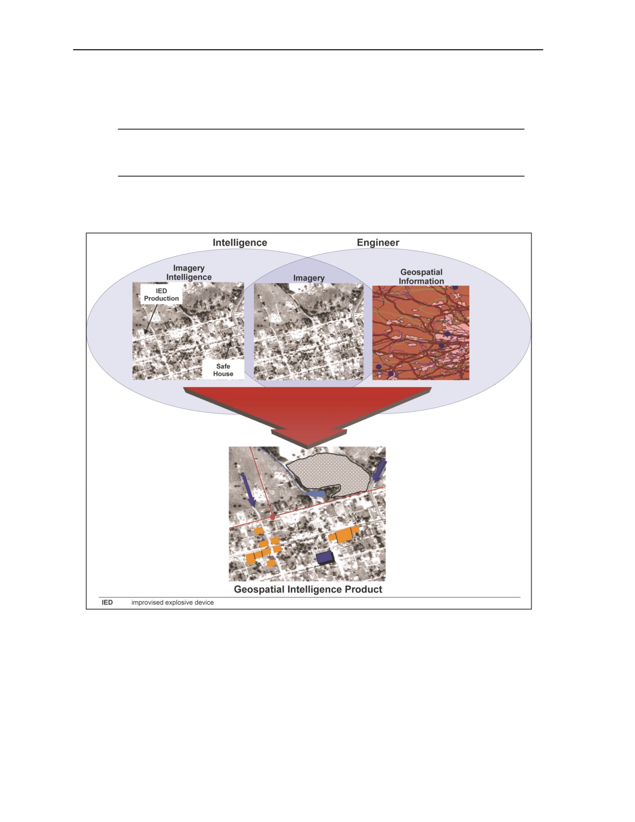
1-5. GEOINT consists of layered data combined into a single product. (See figure 1-1.)
Figure 1-1. GEOINT data layering
1-6. The foundation of a GEOINT product is any one or a combination of the components of GEOINT
(IMINT, geospatial information, or imagery). (See figure 1-2.) The foundation provides information about
a specific location and describes an operational environment.
1-2
TC 2-22.7
18 February 2011
FOR OFFICIAL USE ONLY

Geospatial Intelligence (GEOINT) Overview
Figure 1-2. GEOINT foundation
1-7. Any geospatially referenced information, commonly referred to as data layers (see figure 1-3), can be
added to the GEOINT foundation to enhance visualization of the operational environment. These value-
added layers visually depict information provided by other intelligence disciplines and nonintelligence data
as supplemental information (figure 1-3). A GEOINT product (see figure 1-4, page 1-4) may consist of the
GEOINT foundation layer or layers (IMINT, imagery, or geospatial information) as well as one or more
supplemental data layers, depending on what information is needed. GEOINT products have no layer limit.
Figure 1-3. Value-added layers
1-8. Intelligence discipline data in supplemental
(value-added) data layers provides corroboration,
context, and additional details to the battle command staff. Nonintelligence data layers provide more details
by addressing subject areas such as battlefield geometry, civil considerations, and weather.
18 February 2011
TC 2-22.7
1-3
FOR OFFICIAL USE ONLY

Chapter 1
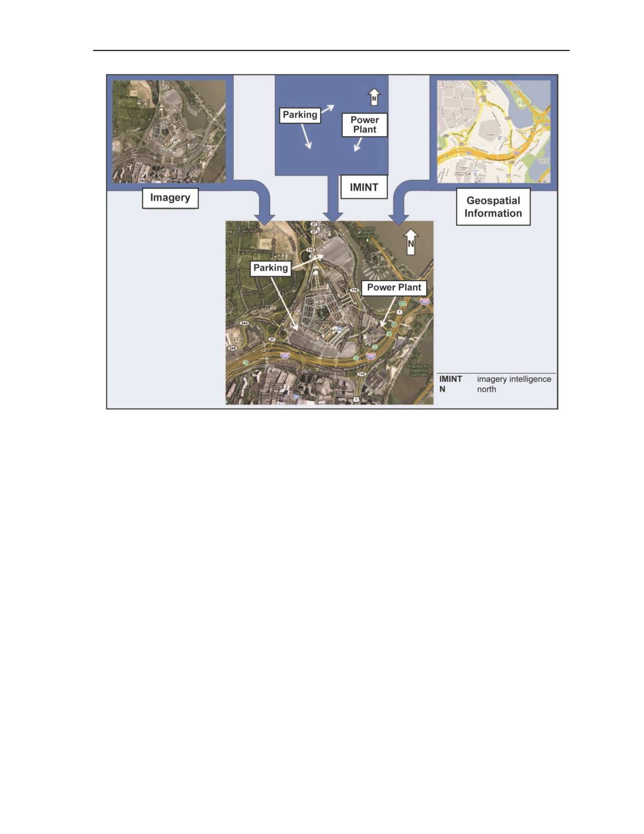
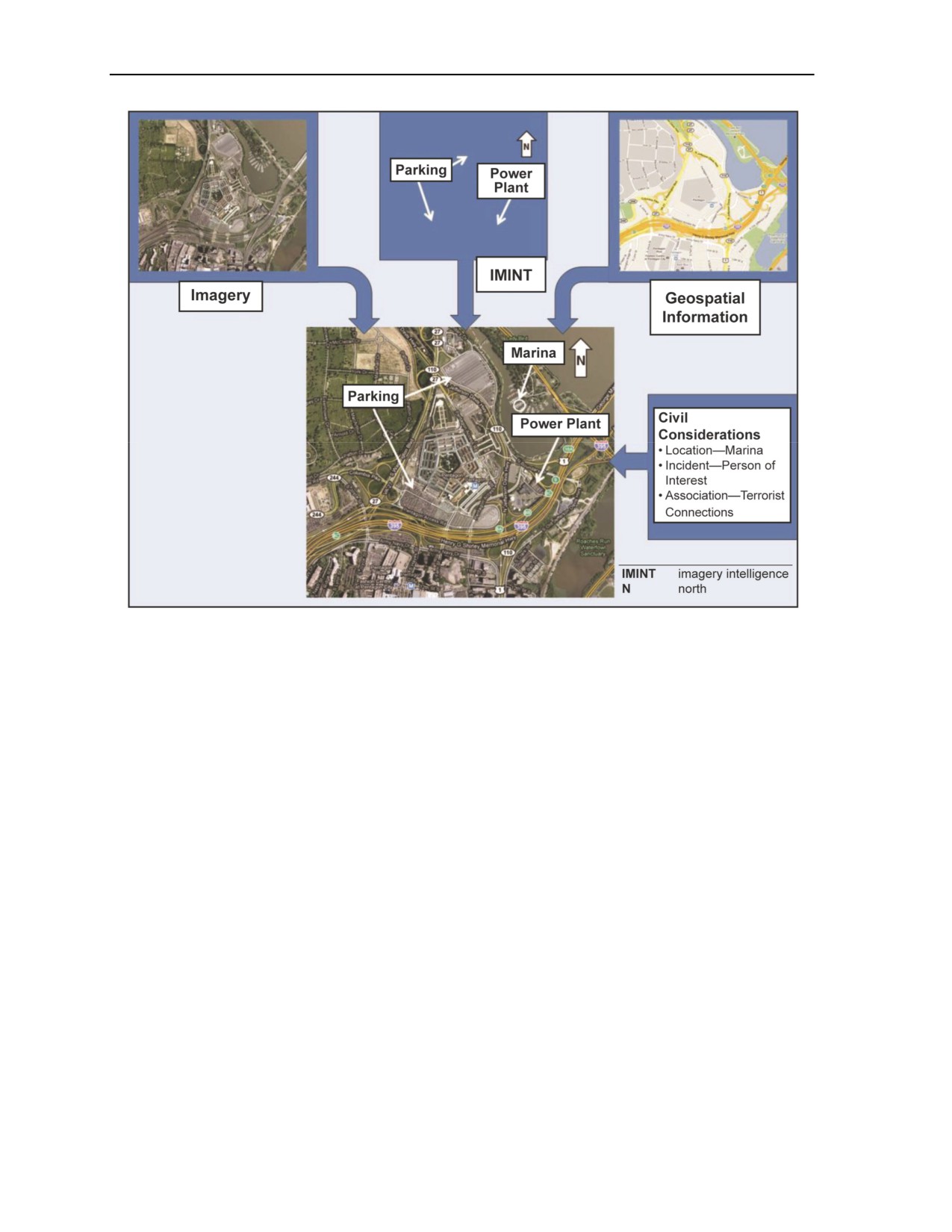
1-9. Figures 1-4, 1-5, and 1-6 illustrate the progressive layering of intelligence information to further
enhance a GEOINT product. Figure 1-4, page 1-4, shows the combination of an image and geospatial
information. In figure 1-5, IMINT is added. Lastly, figure 1-6, page 1-6, incorporates information related to
civil considerations.
Figure 1-4. GEOINT product—imagery and geospatial information
1-4
TC 2-22.7
18 February 2011
FOR OFFICIAL USE ONLY
Geospatial Intelligence (GEOINT) Overview
Figure 1-5. GEOINT product—imagery and IMINT and geospatial information
18 February 2011
TC 2-22.7
1-5
FOR OFFICIAL USE ONLY
Chapter 1
Figure 1-6. GEOINT product—GEOINT and civil considerations
THE NATIONAL SYSTEM FOR GEOSPATIAL INTELLIGENCE
1-10. Many ongoing operations and activities across DOD involve GEOINT. The NSG manages
operations through guidance, policy, programs, and organizations with the intent to provide
decisionmakers, commanders, intelligence users and producers, and civil authorities a better understanding
of GEOINT to effectively execute assigned missions.
1-11. The NSG is the combination of technology, policies, capabilities, doctrine, activities, people, data,
and communities necessary to produce GEOINT that can be readily integrated into intelligence analysis,
products, and reports disseminated across multiple environments.
1-12. The NSG community comprises—
z
NSG members. Members are responsible for prioritizing, planning, programming, budgeting,
acquiring, collecting, analyzing, producing, sharing, storing, and processing GEOINT. Members
include—
The intelligence community.
Joint staff.
Military departments (including the Services).
Combatant commands.
z
NSG partners. Partners influence or indirectly participate in GEOINT prioritization, collection,
production, or related programming and budgeting. Partners include—
Civil applications committee members.
International partners.
1-6
TC 2-22.7
18 February 2011
FOR OFFICIAL USE ONLY
Geospatial Intelligence (GEOINT) Overview
Industry.
Academia.
Defense service providers.
Civil community service providers.
NATIONAL ORGANIZATIONS THAT SUPPORT THE NSG
1-13. The following organizations participate with the Army to support the NSG and may or may not be
NSG members or partners:
z
NGA.
z
Defense Intelligence Agency (DIA).
z
National Security Agency (NSA).
z
National Reconnaissance Office (NRO).
z
Office of Naval Intelligence (ONI).
z
Marine Corps Intelligence Activity (MCIA).
z
National Air and Space Intelligence Center (NASIC).
National Geospatial-Intelligence Agency
1-14. NGA is the functional manager for GEOINT and a national-level intelligence community member
that is responsible for the following major tasks, as outlined in DODD 5105.60:
z
Provides timely, relevant, and accurate GEOINT to DOD, intelligence community, and other
U.S. Government departments and agencies.
z
Manages national imagery tasking, procedures, standards, and acquisitions.
z
Conducts other intelligence-related activities essential for U.S. national security.
z
Provides GEOINT for safety of navigation information.
z
Prepares and distributes maps, charts, books, and geodetic products.
z
Designs, develops, operates, and maintains systems related to the processing and dissemination
of GEOINT.
z
Provides GEOINT support to the Armed Forces.
1-15. NGA’s director serves as the functional manager for GEOINT in accordance with applicable laws
and guidance from the Director of National Intelligence (DNI) and DOD directives and agreements. As
functional manager, the NGA director—
z
Serves as principle advisor to DNI for performance of the GEOINT function.
z
Exercises functional management and oversight of the NSG, including technical oversight of
NSG tactical elements, to ensure—
Interoperability between existing and future NSG systems.
Connectivity between national and tactical systems.
Modernization of tactical systems.
z
Manages GEOINT activities.
z
Sets standards for GEOINT architecture and products.
z
Provides technical guidance for systems using GEOINT.
The National Geospatial-Intelligence Agency’s Allied System for GEOINT
1-16. NGA recognizes that GEOINT is greater than NGA and U.S. resources. Although the NSG produces
and participates in providing GEOINT to the Nation’s decisionmakers and warfighters, the NSG’s success
also depends on collaborating closely with multinational partners on a day-to-day basis. To reflect this
reality, NGA has expanded its operating model to more fully incorporate the valuable input of the Nation’s
closest multinational partners. Therefore, it is now operating the Allied System for GEOINT (ASG). The
18 February 2011
TC 2-22.7
1-7
FOR OFFICIAL USE ONLY
Chapter 1
NSG joins Australia, Canada, New Zealand, and the United Kingdom to form an international GEOINT
community, with each member building on the contributions of others and underlining the strengths of each
nation. ASG is a platform for cooperation on issues that range from—
z
Standards to technology.
z
Training to fulfilling joint requirements in topographic, aeronautical, and nautical areas and in
theaters of operations.
1-17. NGA maintains Web sites and e-mail on the Nonsecure Internet Protocol Router Network
(NIPRNET), SECRET Internet Protocol Router Network (SIPRNET), and Joint Worldwide Intelligence
Communications System (JWICS). Commanders and staffs can access NGA products directly from these
information on NGA.)
National Geospatial-Intelligence Agency Support Teams
1-18. The primary mechanism for interaction between combatant commands and NGA is the NGA support
team. The team’s mission is to—
z
Provide timely, accurate, and tailored GEOINT to combatant commands during peacetime,
throughout exercises, and during war.
z
Act as a conduit for ensuring full fusion of available information between combatant commands
and NGA.
1-19. NGA support team coordinates NGA’s operational, policy, and training support to its customers.
NGA maintains NGA support teams at the joint staff, combatant commands, Services, and DOD agencies.
A typical NGA support team comprises a senior representative (a military intelligence [MI] senior officer
or a defense intelligence senior leader), staff officers, and imagery and geospatial analysts. A reach
component at NGA headquarters focuses NGA production support.
1-20. In addition to using NGA support teams, NGA, upon request, may deploy crisis support teams of two
to five imagery and geospatial analysts—either independently as augmentation to an existing NGA support
team or as part of a national intelligence support team (NIST).
1-21. A national intelligence support team is a nationally sourced team composed of intelligence and
communications experts from the Defense Intelligence Agency, Central Intelligence Agency, National
Geospatial-Intelligence Agency, National Security Agency, or other intelligence community agencies as
required (JP 2-0). A NIST can comprise a combination of these agencies or depending on the mission, may
include other intelligence community organizations, as well. A NIST provides the means to integrate
national intelligence capabilities into a comprehensive intelligence effort designed to support the joint
force.
(See JP
2-01.) These government or contract personnel teams employ deployable GEOINT
production systems. NIST personnel reach to NGA for data and products; fuse this information with
tactical, operational, and strategic sources; and collaborate with users to produce products tailored to their
needs.
Defense Intelligence Agency
1-22. DIA is a national-level intelligence agency responsible for providing MI to commanders, defense
planners, and defense and national security policymakers. As the proponent for the defense intelligence
enterprise, DIA—
z
Has oversight of the Defense Intelligence Analysis Program.
z
Is a consumer of GEOINT products produced by NGA and other members of the NSG.
z
Develops imagery-based products that assist theater, corps, division, and brigade combat team
(BCT) intelligence staffs in performing those tasks associated with—
Intelligence preparation of the battlefield (IPB).
Indications and warning (I&W).
Situation development.
1-8
TC 2-22.7
18 February 2011
FOR OFFICIAL USE ONLY
Geospatial Intelligence (GEOINT) Overview
Intelligence, surveillance, and reconnaissance (ISR).
Targeting.
1-23. DIA maintains Web sites and e-mail on NIPRNET, SIPRNET, and JWICS. Commanders and staffs
can access DIA products directly from these Web sites or communicate directly with DIA analysts via e-
National Security Agency
1-24. NSA is a national-level intelligence agency responsible for protecting U.S. national security systems
and producing foreign signals intelligence
(SIGINT) information. Its primary mission is to produce
SIGINT, provide information assurance products and services, and enable network warfare operations.
1-25. NSA has oversight of all U.S. SIGINT operations and is a consumer of GEOINT products by NGA
and other members of the NSG. It does not produce geospatial or imagery-based products for external
users.
1-26. NSA maintains Web sites and e-mail on NIPRNET, SIPRNET, and JWICS.
(Go to
National Reconnaissance Office
1-27. NRO is a national-level intelligence agency that builds and operates the Nation’s satellites, which
support DOD and the Central Intelligence Agency (CIA). NRO is a provider of imagery data for analysis
by the NSG. It does not produce geospatial or imagery-based products for external users.
(Go to
Office of Naval Intelligence
1-28. ONI produces maritime intelligence to support strategic, operational, and tactical commanders. ONI
is a consumer of GEOINT products produced by NGA and other members of the NSG. ONI develops
GEOINT related to threats and to friendly air, surface and subsurface, and landing forces.
(Go to
http://www.oni.navy.mil for more information on the ONI. Also, see Naval Doctrine Publication 2, Naval
Intelligence.)
Marine Corps Intelligence Activity
1-29. MCIA produces intelligence to support expeditionary warfare. MCIA is a consumer of GEOINT
products produced by NGA and other members of the NSG. MCIA develops GEOINT related to threat and
terrain-analysis tailored products for Marine Corps tactical units preparing to deploy to a theater of
operations. (Go to http://www.quantico.usmc.mil/activities/?Section=MCIA for more MCIA information.)
National Air and Space Intelligence Center
1-30. NASIC is the source of air and space intelligence for DOD and produces intelligence that enables
military operations. NASIC provides intelligence assessments and tailored intelligence products directly to
operational military units. NASIC produces intelligence related to foreign air and space capabilities,
including weapons system performance, vulnerabilities, and employment, which includes—
z
Aircraft.
z
Ballistic missiles.
z
Radars.
z
Integrated air defense systems.
z
Electronic and electro-optical countermeasures.
z
Command and control information systems.
18 February 2011
TC 2-22.7
1-9
FOR OFFICIAL USE ONLY
Chapter 1
1-31. NASIC is a producer of GEOINT as well as a consumer of GEOINT products produced by NGA and
other members of the NSG. (Go to http://www.afisr.af.mil/units/nasic/index.asp for more information on
NASIC.)
ARMY ORGANIZATIONS THAT SUPPORT THE NSG
1-32. In addition to national organizations, the following Army organizations described below also support
the NSG:
z
Army Special Programs Office (ASPO).
z
National Ground Intelligence Center (NGIC).
z
Army Geospatial Intelligence Office (AGO).
z
Army Geospatial Center (AGC).
Army Special Programs Office
1-33. ASPO is an Army acquisition organization (subordinate to the Program Executive Office [PEO] for
Intelligence, Electronic Warfare, and Sensors [IEW&S]) responsible for four operational Army programs,
one of which is the tactical exploitation of national capabilities program (TENCAP). ASPO, through the
TENCAP program manager, enables Army forces to access, exploit, and disseminate national technical
means (NTM) data using the TENCAP-developed Tactical Exploitation System family of systems. ASPO
collaborates closely with NSG members to ensure the Army’s operational forces are empowered by
technology, information, and the ability to fuse MI disciplines. Army forces, using the Tactical Exploitation
more information on ASPO.)
National Ground Intelligence Center
1-34. NGIC is a U.S. Army Intelligence and Security Command (INSCOM) functional command with
operational control exercised by the Headquarters, Department of the Army, Deputy Chief of Staff, G-2.
NGIC is responsible for the development of finished, all-source intelligence on foreign ground forces under
the federated Defense Intelligence Analysis Program. It provides scientific and technical intelligence
(S&TI) and general military intelligence (GMI) on foreign ground forces to support senior defense and
Army leadership, warfighting commanders, and force and materiel developers. NGIC also provides
GEOINT support to combatant commands through the embedded NGA support team, as well as the Army
GEOINT Battalion.
1-35. NGIC’s mission is to produce and disseminate all-source integrated intelligence on foreign ground
forces and related military technologies to ensure U.S. forces have a decisive edge on current and future
military operations. Following are NGIC’s core competencies:
z
Analysis of how foreign ground forces (regular and irregular) organize, equip, train, and operate,
including improvised explosive device procurement, production, employment, effects, and
networks.
z
Analysis of past and present patterns and prediction of future capabilities.
z
In-depth analysis of current and projected foreign ground force materiel.
z
Analysis of foreign weapon effects and the threat they pose to U.S. materiel.
z
Technology forecasts for modernization programs.
z
Assessments of integrated warfighting functions.
z
Imagery exploitation and analysis.
z
Measurement and signature intelligence (MASINT).
z
Document and media exploitation (DOMEX).
z
Biometric-enabled intelligence (BEI).
z
Foreign materiel acquisition and exploitation.
1-10
TC 2-22.7
18 February 2011
FOR OFFICIAL USE ONLY
Geospatial Intelligence (GEOINT) Overview
z
Chemical and biological warfare assessments, including—
Consequence assessments from the release of toxic and chemical and biological warfare
agents.
Employment of weapons of mass destruction to support threat operational forces.
z
Analysis and production of irregular warfare threats with focus on regional and transregional
networks.
z
Scientific and technical analysis of military-grade and improvised weapon systems.
z
Types, characteristics, and performance of improvised explosive devices and associated tactics,
techniques, and procedures.
1-36. NGIC comprises the 2d MI Center located in Charlottesville, Virginia. The center includes a
subordinate command element, the Army GEOINT Battalion, which is embedded within NGA in
Washington, DC. The Army GEOINT Battalion represents Army interests at NGA. The 2d MI Center—
z
Advocates for Army requirements for broad-spectrum imagery products and support while
contributing to NGIC’s overall GMI and S&TI mission.
z
Provides GEOINT tactical overwatch of deployed forces.
z
Provides crisis support for the Army and DOD agencies.
z
Provides GEOINT sustainment training to support the Army.
1-37. NGIC’s National-to-Theater Program is the DOD leader in providing innovative advanced geospatial
intelligence (AGI) to joint and component warfighters. Advanced geospatial intelligence refers to the
technical, geospatial, and intelligence information derived through interpretation or analysis using
advanced processing of all data collected by imagery or imagery-related collection systems (JP 2-03). This
definition of AGI, which is also known as imagery-derived MASINT, includes information technically
derived from the processing, exploitation, and nonliteral analysis (including integration of fusion) of
spectral, spatial, temporal, radiometric, phase history, and polarimetric data. Through INSCOM, national-
to-theater AGI products enable customers to improve targeting and increase situational awareness.
1-38. The National-to-Theater Program performs AGI processing to extract unique information and expand
on traditional imagery capabilities by directly leveraging NTM and theater collection assets. The Army
National-to-Theater Program comprises numerous GEOINT teams (nodes), each co-located with INSCOM
MI brigades, NGIC, and the Army Forces Strategic Command, thus providing GEOINT support to all
regional combatant commands.
1-39. Go to http://www.inscom.army.mil/Default.aspx?text=off&size=12pt for more information on NGIC.
Army Geospatial Intelligence Office
1-40. AGO is the designated Service-level element. AGO—
z
Provides integrated and coordinated liaison with NGA for executive agents within the Army
responsible for the key components of Army GEOINT.
z
Develops plans, programs, budgets, and policy related to Army-specific GEOINT activities.
z
Assists the Army Geospatial Information Officer in coordinating GEOINT policy within the
Army, with the NSG, and with oversight organizations.
1-41. AGO also facilitates GEOINT federation and integration into the NSG by coordinating Army
GEOINT tasking, collection, processing, exploitation, and dissemination (TCPED) functions, as well as
federated production and capability development. AGO accomplishes its purpose through a team
arrangement that unites single-coordinated entities, elements from the Army G-2, INSCOM organizations,
and the Army Geospatial Information Office. This coordination affects unified operations, tradecraft,
policy, data standard, system acquisition, research and development, and resourcing for integration of
GEOINT throughout the Army.
18 February 2011
TC 2-22.7
1-11
FOR OFFICIAL USE ONLY
Chapter 1
Army Geospatial Center
1-42. With increasing demand for geospatial support at all echelons, the Army created AGC, which
replaced the Engineer Research and Development Center’s Topographic Engineering Center (TEC). AGC
is a direct reporting unit under the U.S. Army Corps of Engineers (USACE). AGC provides timely,
accurate, geospatial support to warfighters and expands its mission to support the Army Battle Command
System (ABCS) by facilitating the dissemination of relevant geospatial information to every level across
the dynamic operational environment. Additionally, the center coordinates, integrates, and synchronizes
geospatial information requirements and standards across the Army as well as develops and fields
geospatial enterprise-enabled systems and capabilities to the Army and DOD.
1-43. AGC is designated as the Army knowledge center for geospatial expertise. The Army Geospatial
Information Officer is also the AGC director. The Army Geospatial Information Officer, as the Army’s
central manager, is responsible for coordinating, assessing, and synchronizing Army policies and for
standardizing requirements for the geospatial information enterprise. (Go to http://www.agc.army.mil for
more information on AGC.)
GEOINT SUPPORT TO COMBATANT COMMANDS
1-44. Combatant commands develop area and point target GEOINT requirements to conduct joint
operations. Each combatant command has also established a joint intelligence operations center to plan,
prepare, integrate, direct, synchronize, and manage continuous, intelligence operations. The center’s goal is
the integration of intelligence, operations, and plans to increase the speed, power, and combat effectiveness
of DOD operations. These organizations facilitate access to all available intelligence sources. They analyze,
produce, and disseminate accurate and timely all-source intelligence and GEOINT to conduct military
operations.
1-45. At the theater, corps, division, brigade, battalion, and company levels, the commander’s primary
requirement for GEOINT is the timely production of GEOINT products that aid mission command,
command and control, the military decisionmaking process (MDMP), situation development, I&W, and
targeting.
1-46. Theater, corps, division, and brigade commanders have organic GEOINT assets that support them.
Battalion and company commanders depend mainly on brigade assets to support them. When requirements
exceed a commander’s organic GEOINT capability, additional support is available through the NSG.
1-47. The NSG is designed to be a mutually supportive enterprise that fosters collaboration between
echelons to ensure Army commanders have the GEOINT needed to support operations. When developing
intelligence architectures, G-2s/S-2s develop communications protocols and professional relationships with
each relevant component of the NSG. When conducting ISR planning, G-2s/S-2s leverage the support each
of these components can provide.
1-48. Commanders generally employ organic GEOINT resources against time-sensitive and critical
information needs. They rely on nonorganic resources to provide mid- to long-term collection and analysis.
Commanders rely on G-2s/S-2s to understand how to use nonorganic GEOINT resources that have or can
collect data related to a theater of operations. The NGA can assist G-2s/S-2s in identifying those
organizations or agencies that should be included in the command’s intelligence architecture. The NGA can
also provide advice on integrating NSG members and partners into ISR strategies. This accomplishment
leverages the full power of GEOINT for the Army, resulting in more comprehensive and tailored
intelligence products across warfighting functions.
INTELLIGENCE PRODUCTS AND GEOINT
1-49. Intelligence products are generally placed in one of seven production categories:
z
I&W.
z
Current intelligence.
z
GMI.
1-12
TC 2-22.7
18 February 2011
FOR OFFICIAL USE ONLY
Geospatial Intelligence (GEOINT) Overview
z
Target intelligence.
z
S&TI.
z
Counterintelligence.
z
Estimative intelligence.
1-50. The categories of intelligence are distinguishable based on the purpose of the intelligence product.
The categories can overlap and some of the same intelligence is useful in more than one category.
Depending upon the echelon, intelligence organizations may use specialized procedures to develop each
intelligence category. The following information briefly describes each category and its GEOINT
connection. (See FM 2-0 for more information on the seven production categories.)
INDICATIONS AND WARNING
1-51. Indications and warning are those intelligence activities intended to detect and report time-sensitive
intelligence information on foreign developments that could pose a threat to the United States or allied
and/or coalition military, political, or economic interests or to U.S. citizens abroad. It includes forewarning
of hostile actions or intentions against the United States, its activities, overseas forces, or allied and/or
coalition nations (JP 2-0). I&W includes—
z
Forewarning of threat actions or intentions.
z
The imminence of hostilities.
z
Insurgency.
z
Nuclear or non-nuclear attack on the United States, U.S. overseas forces, or multinational forces.
z
Hostile reactions to U.S. reconnaissance activities.
z
Terrorist attacks.
z
Other similar events.
1-52. See FM 2-0 for more information on I&W.
CURRENT INTELLIGENCE
1-53. Current intelligence is concerned with describing the existing situation (JP 2-0). Current intelligence
involves the integration of time-sensitive, all-source intelligence and information into concise, accurate,
and objective reporting on the area of operations (AO) and current threat situation. One of the most
important forms of current intelligence is the threat situation portion of the COP and as such derives much
of its information from GEOINT.
GENERAL MILITARY INTELLIGENCE
1-54. General military intelligence is intelligence concerning the
(1) military capabilities of foreign
countries or organizations or (2) topics affecting potential U.S. or multinational military operations, relating
to the following subjects: armed forces capabilities, including order of battle, organization, training, tactics,
doctrine, strategy, and other factors bearing on military strength and effectiveness; area and terrain
intelligence, including urban areas, coasts and landing beaches, and meteorological, oceanographic, and
geological intelligence; transportation in all modes; military materiel production and support industries;
military and civilian communications systems; military economics, including foreign military assistance;
insurgency and terrorism; military political-sociological intelligence; location, identification, and
description of military related installations; government control; escape and evasion; and threats and
forecasts (excludes scientific and technical intelligence) (JP 2-0).
1-55. A current and comprehensive intelligence database is critical to plan and prepare rapidly for
operations. The G-2/S-2 develops and maintains the unit’s GMI database as an essential component of
intelligence readiness. The GMI database supports the unit’s conduct of operations and reflects the use of
GEOINT throughout the data it maintains.
18 February 2011
TC 2-22.7
1-13
FOR OFFICIAL USE ONLY
Chapter 1
TARGET INTELLIGENCE
1-56. Target intelligence is intelligence that portrays and locates the components of a target or target
complex and indicates its vulnerability and relative importance (JP 3-60). It entails the analysis of threat
units, dispositions, facilities, and systems to identify and nominate specific assets or vulnerabilities for
attack, reattack, or exploitation
(for intelligence). GEOINT products and information are a critical
component for the successful prosecution of this activity.
SCIENTIFIC AND TECHNICAL INTELLIGENCE
1-57. Scientific and technical intelligence is the product resulting from the collection, evaluation, analysis,
and interpretation of foreign scientific and technical information that covers: a. foreign developments in
basic and applied research and in applied engineering techniques; and b. scientific and technical
characteristics, capabilities, and limitations of all foreign military systems, weapons, weapon systems, and
materiel; the research and development related thereto; and the production methods employed for their
manufacture (JP 2-01).
1-58. Details provided through GEOINT products and information enables the S&TI analyst to perform the
evaluation, analysis, and interpretation aspects of this capability.
COUNTERINTELLIGENCE
1-59. Counterintelligence is information gathered and activities conducted to identify, deceive, exploit,
disrupt, or protect against espionage, other intelligence activities, sabotage, or assassinations conducted for
or on behalf of foreign powers, organizations, or persons, or their agents, or international terrorist
organizations or activities (Executive Order 12333 [EO 12333]).
1-60. Counterintelligence includes all actions taken to detect, identify, track, exploit, and neutralize the
multidiscipline intelligence activities of threats. It is the key intelligence community contributor to protect
U.S. interests and equities. (See FM 2-0.) GEOINT support to counterintelligence includes the construction
of tactical decision aids that help identify threat ISR operations, such as infiltration routes.
ESTIMATIVE INTELLIGENCE
1-61. Estimative intelligence identifies, describes, and forecasts threat capabilities and the implications for
planning and executing military operations (JP 2-0). The addition of GEOINT products and information to
the estimative process helps forecast the unknown based on an analysis of known facts and using
techniques, such as pattern analysis, inference, and statistical probability.
1-14
TC 2-22.7
18 February 2011
FOR OFFICIAL USE ONLY
Chapter 2
Imagery
Imagery is one of three components of GEOINT, as defined in chapter 1. Imagery is
the visual basis of GEOINT, enabling the intelligence staff to “see” the operational
environment without actually being there. Characteristics within this chapter include
imagery sources, resolution, and types.
IMAGERY SOURCES
2-1. Imagery sources include—
z
Satellite systems:
NTM.
Commercial or civil satellite systems.
Overhead persistent infrared (OPIR).
z
Aircraft systems:
Manned.
Unmanned.
z
Handheld imagery (derived from other than human intelligence [HUMINT] sources):
Ground reconnaissance.
Open-source intelligence.
SATELLITE SYSTEMS
2-2. Space-based platforms have been a critical component for imagery collection since their inception in
the 1960s. NRO, in collaboration with the Services and other government agencies, designs, builds, and
operates the Nation’s reconnaissance satellites.
2-3. National reconnaissance platforms and commercial or civil imaging satellites use of domestic
imagery operate under legal and policy limitations derived from the U.S. Constitution, EO 12333, goals,
direction, duties, and responsibilities with respect to the national intelligence effort and the National
Security Act of 1974, as amended, as well as other applicable law and policy directives. Users must be
aware of legal and policy concerns associated with domestic imagery, particularly if they pertain to private
property. Individuals may be held responsible for any violation of law or inappropriate use of domestic
imagery. (See chapter 6, paragraphs 6-28 through 6-30.)
2-4. While commercial or civil imagery is unclassified, caution must be exercised when requesting and
obtaining imagery from commercial or civil organizations for operations security reasons. Acquiring
commercial or civil imagery is generally not a secure process, and the imagery collected can be placed on a
publicly available archive for resale by the vendor.
National Technical Means
2-5. NTM provides timely, relevant, and accurate imagery and GEOINT to support the Nation’s military
forces, national policymakers, and civil users. National systems are a primary source of imagery used to
produce GEOINT. However, imagery collected from national systems is classified; therefore, it requires
release authorization, making dissemination more difficult. NTM imagery and products are disseminated
18 February 2011
TC 2-22.7
2-1
FOR OFFICIAL USE ONLY
Chapter 2
via numerous libraries or directly on the SIPRNET. Recently, NGA authorized the release of some NTM
data at the unclassified//for official use only (U//FOUO) level.
Commercial or Civil Satellite Systems
2-6. Commercial systems collect panchromatic (visible), spectral, and radar data, and have a broader
scope of operations than national systems. Commercial systems and commercial producers from foreign
and U.S. vendors increasingly contribute geospatial information and products for NSG requirements.
2-7. Commercially available, submeter resolution imagery and geospatial information are becoming more
widely used as the intelligence community seeks more cost-effective ways of providing a full range of
imagery-based products to an ever-growing customer base. Commercial imagery provides an important
advantage in multinational operations because it is unclassified and can be disseminated without
compromising the capabilities and operating characteristics of U.S. national reconnaissance systems.
2-8. Due to their flexibility and resolution capabilities, commercial satellite collectors are increasingly
relied upon to augment NTM. For example, commercial aircraft imagery systems are used for planning
support to national special security events, such as the Olympics, and national political conventions.
Overhead Persistent Infrared
2-9. OPIR is a defense program of remotely sensed data provided in large spatial samples, including—
z
Short-wave infrared (SWIR).
z
Near infrared (IR).
z
Medium-wave infrared (MWIR).
z
Visible.
z
Long-wave infrared (LWIR).
z
Ultraviolet spectral bands.
AIRCRAFT SYSTEMS
2-10. Aircraft systems are ISR assets residing at the theater and tactical levels. These aircraft systems are
tasked and managed through the command’s ISR plan. TC 2-01 contains additional information on ISR and
ISR synchronization. The full spectrum of GEOINT aircraft ISR sources includes all manned and
unmanned platforms that collect still and motion imagery using panchromatic (visible), thermal, multiband,
multispectral, hyperspectral, laser-based, or radar-based imaging sensors. Aircraft systems can be either
government or commercial systems.
2-11. Commercial aircraft systems provide yet another source of imagery and geospatial information. For
example, due to their flexibility and resolution capabilities, commercial aircraft collectors are increasingly
relied upon to augment satellite collection.
2-12. Aircraft systems are capable of locating and recognizing major threat forces, moving vehicles,
weapons systems, and other targets that contrast with their surroundings. In addition, aircraft systems are
capable of locating and confirming the position of friendly forces, presence of noncombatant civilians, and
so forth. Current Army aircraft system missions include—
z
Reconnaissance.
z
Surveillance.
z
Security.
z
Cooperative engagements.
z
Communications relay.
2-13. Currently, aircraft systems bring numerous capabilities to Army units, such as—
z
Providing near real-time reconnaissance, surveillance, and target acquisition.
z
Providing excellent reconnaissance and attack resolution.
z
Being fitted with laser designators to mark targets and some may be armed.
z
Supporting target acquisition efforts and lethal attacks on threat reconnaissance and advance
forces.
2-2
TC 2-22.7
18 February 2011
FOR OFFICIAL USE ONLY
Imagery
z
Assisting in route, area, and zone reconnaissance.
z
Locating and helping to determine threat force composition, disposition, and activity.
z
Maintaining contact with threat forces from initial contact through battle damage assessment.
z
Providing target coordinates with enough accuracy to enable an immediate target handover, as
well as first-round fire-for-effect engagements.
z
Providing or enhancing spectral sensor coverage of the AO.
z
Providing information to other aircraft systems, thus increasing survivability.
z
Providing extended three-dimensional (3D) vantage, in both distance and time, at critical
decision points in difficult terrain.
z
Performing decoy, demonstration, feint, and deception operations.
z
Providing digital connectivity, allowing for rapid product dissemination.
Manned Aircraft Imaging Systems
2-14. Manned aircraft systems include but are not limited to the following examples:
z
U-2.
z
Joint Surveillance Target Attack Radar System (JSTARS).
z
Airborne Reconnaissance Low (ARL).
z
Airborne Reconnaissance Multisensor System (ARMS).
z
Medium Altitude Reconnaissance and Surveillance System (MARSS).
z
Constant Hawk.
z
Enhanced-Medium Altitude Reconnaissance and Surveillance System (EMARSS).
z
Project Liberty.
U-2
2-15. The Lockheed U-2 (see figure 2-1, page 2-6), nicknamed Dragon Lady, is a single-engine, high-
altitude aircraft flown by the U.S. Air Force (USAF) and previously flown by the CIA. It provides day and
night, high-altitude (70,000 feet), all-weather surveillance. It can use both line-of-sight and beyond line-of-
sight data links.
2-16. The U-2 carries a variety of sensors capable of simultaneously collecting SIGINT and IMINT.
Although the U-2 is capable of collecting with multidiscipline sensors simultaneously, it is limited to one
imagery sensor at a time. IMINT sensors include—
z
Optical bar camera (OBC)—a 30-inch panoramic format film sensor. It is the only wet-film
system still in operation in the USAF. A full roll of film can provide more than 100,000 square
nautical miles coverage.
z
Senior Year Electro-Optical Reconnaissance System (SYERS)—a multispectral visible/IR
image that provides deep-look, high-resolution, near real-time imagery. The multispectral
capability improves imaging capabilities in night, foggy, or hazy conditions. It provides
improved resolution, range, and geo-location accuracy, as well as improved performance in
darkness, haze, and inclement weather. When the sensor is out of range from a ground receive
location, collected image data can be stored for later retrieval.
z
Advanced Synthetic Aperture Radar System 2A (ASARS-2A)—a near real-time, high-
resolution radar reconnaissance system with all-weather, day-night, long-range mapping
capabilities. ASARS-2A detects and accurately locates stationary and moving ground targets.
The system can survey more than 100,000 square miles of the Earth’s surface in one hour. The
sensor can scan the ground on either side of the aircraft and acquire images out to around
160 kilometers. The radar operates in either search or spot modes and relays data in near real-
time via a wideband data link, with a line-of-sight range close to 300 nautical miles, to a
dedicated ground station.
18 February 2011
TC 2-22.7
2-3
FOR OFFICIAL USE ONLY
Chapter 2
Joint Surveillance Target Attack Radar System
2-17. JSTARS and the common ground station (CGS) are coupled to provide timely moving target
indicator
(MTI) data. This data provides important insight on object movements during overseas
contingency operations.
2-18. JSTARS is a USAF aircraft battle management and command and control platform that conducts
ground surveillance to develop an understanding of the threat situation. These functions support the
primary mission of JSTARS—to provide dedicated support of ground and air theater commanders.
Although JSTARS is operated and maintained by the USAF, it is considered a national asset for tasking
purposes. Its primary mission is the dedicated support of a joint task force’s (JTF’s) joint force-land
component commander or geographic combatant commander under the overall direction of the joint force
commander (JFC).
2-19. The JSTARS sensor suite provides detection and tracking of moving targets via MTIs, fixed target
indicators, and synthetic aperture radars
(SARs). Radar data collected by JSTARS (see figure 2-2,
page 2-7) is distributed via an onboard local area network (LAN) to an encrypted, highly jam-resistant
surveillance and control data link for real-time transmission to an unlimited number of CGSs.
2-20. As a battle management and command and control asset, JSTARS supports a wide range of roles and
missions across the spectrum of conflict. JSTARS can detect moving vehicles, providing the approximate
number of vehicles, their location, speed, direction of travel, and the time that the vehicles were detected.
Identifying who the targets are, what equipment they have, whether they are friendly, hostile, or bystanders,
is not possible with this system. Other service sensors may reference each other to positively validate
JSTARS reports.
2-21. To support air-to-ground operations, JSTARS can provide real-time information needed to increase
ground-situation awareness with intelligence support, attack support, and targeting operations, including
attack aviation, naval surface fire, field artillery, and friendly maneuver forces. It also provides information
for air and land commanders to gain and maintain control of the AO and execute operations against threat
forces.
Airborne Reconnaissance Low
2-22. ARL (see figure
2-3, page
2-8) is a multifunction, day or night, all-weather reconnaissance
intelligence asset developed and fielded by the Army to support a requirement for a low-profile intelligence
aircraft. It consists of a modified DHC-7 fixed-wing aircraft equipped with IMINT and communications
intelligence mission payloads. Some variations incorporate an MTI/SAR mission payload. The payloads
are controlled and operated via onboard workstations. Intelligence collected on ARL can be analyzed and
recorded on the aircraft workstations in real-time or stored onboard for postmission processing. The ARL
system includes a variety of communications subsystems to support near real-time dissemination of
intelligence and dynamic retasking of the aircraft.
Airborne Reconnaissance Multisensor System
2-23. ARMS is a modified C-12R aircraft (see figure 2-4, page 2-9) equipped with a MX-15 electro-optical
camera with enhanced forward looking infrared (FLIR), color spotter, wide zoom capabilities, laser
illuminator, laser designator, embedded navigation, and precision geo-location capabilities. ARMS
provides mission commanders a simultaneous downlink of video imagery that can be used to identify
convoy hazards and targets for quick-reaction forces to engage.
Medium Altitude Reconnaissance and Surveillance System
2-24. MARSS is a modified C-12 aircraft (see figure 2-5, page 2-10) equipped with a MX-15 electro-
optical camera with enhanced FLIR, laser illuminator, laser designator, and near real-time full motion video
(FMV) downlink. The downlink capability is line-of-sight and beyond line-of-sight. Mission operating
altitude is 5000-14000 feet with an endurance of 5.5 hours. The aircrew consists of two pilots and up to two
onboard analysts who provide real-time imagery analysis for the warfighter on the ground.
2-4
TC 2-22.7
18 February 2011
FOR OFFICIAL USE ONLY
Imagery
Constant Hawk
2-25. Constant Hawk is a modified Sherpa/Shorts 360 aircraft (see figure 2-6, page 2-11) using the
persistent surveillance wide field of view airborne ISR system to conduct counter-improvised explosive
device surveillance force protection missions in Iraq. Constant Hawk uses a special video camera system to
observe a locality and find useful patterns of behavior. Constant Hawk systems are mounted on piloted
aircraft, unmanned light aircraft, and ground structures. Special software compares photos from different
times. When changes are noted, they are checked more closely, which has resulted in the early detection of
roadside bombs and terrorist ambushes.
Enhanced Medium Altitude Reconnaissance and Surveillance System
2-26. EMARSS is a modified C-12 aircraft (see figure 2-7, page 2-12) equipped with a MX-15 electro-
optical camera with enhanced FLIR, laser illuminator, laser designator, and near real-time FMV downlink.
EMARSS also provides communications intelligence and real-time electronic threat characteristic
information for all communications networks and radars in theaters of operations. Communications
intelligence data can be sent to any command level in theaters of operations.
Project Liberty
2-27. The modified C-12W, also known as Project Liberty, is a USAF ISR platform and Air Combat
Command asset (see figure 2-8, page 2-13). It was fielded in 2008 and 2009 to meet ground support ISR
requirements in the U.S. Central Command area of responsibility for Operations Enduring Freedom and
Iraqi Freedom. The modified C-12W platform was created in response to Defense Secretary Robert Gates’
initiative to better support Soldiers on the ground with increased ISR in theaters of operations. Project
Liberty flew its first combat sortie over Iraq on 10 June 2009.
18 February 2011
TC 2-22.7
2-5
FOR OFFICIAL USE ONLY

Chapter 2
Figure 2-1. U-2 manned aircraft system
2-6
TC 2-22.7
18 February 2011
FOR OFFICIAL USE ONLY

Imagery
Figure 2-2. E-8C JSTARS manned aircraft system
18 February 2011
TC 2-22.7
2-7
FOR OFFICIAL USE ONLY

Chapter 2
Figure 2-3. ARL manned aircraft system
2-8
TC 2-22.7
18 February 2011
FOR OFFICIAL USE ONLY

Imagery
Figure 2-4. ARMS manned aircraft system
18 February 2011
TC 2-22.7
2-9
FOR OFFICIAL USE ONLY

Chapter 2
Figure 2-5. MARSS manned aircraft system
2-10
TC 2-22.7
18 February 2011
FOR OFFICIAL USE ONLY

Imagery
Figure 2-6. Constant Hawk manned aircraft system
18 February 2011
TC 2-22.7
2-11
FOR OFFICIAL USE ONLY

Chapter 2
Figure 2-7. EMARSS manned aircraft system
2-12
TC 2-22.7
18 February 2011
FOR OFFICIAL USE ONLY

Imagery
Figure 2-8. Project Liberty manned aircraft system
18 February 2011
TC 2-22.7
2-13
FOR OFFICIAL USE ONLY
Chapter 2
Other Manned Aircraft Imaging Systems
2-28. Table 2-1 lists other aircraft imaging systems that have been used or fielded during Operations
Enduring Freedom and Iraqi Freedom.
Table 2-1. Other manned aircraft systems
Unmanned Aircraft Systems
2-29. Unmanned aircraft system (UAS) platforms perform some or all of the following functions:
z
ISR.
z
Enhanced targeting through acquisition, detection, designation, suppression, and destruction of
threat targets.
z
Support to battle damage assessment and effects assessment.
2-14
TC 2-22.7
18 February 2011
FOR OFFICIAL USE ONLY
Imagery
2-30. UAS missions support the maneuver commander by contributing to effective tactical operations of
smaller units. Ground control stations with the following enhance situational awareness and the COP:
z
Common data links.
z
Remote video terminals and remote operations video enhanced receiver (ROVER).
z
One system remote video transceiver (OSRVT).
z
Portable ground control stations.
z
Army helicopter/Army aircraft command and control system (A2C2S)/UAS teaming.
2-31. UAS operations support commanders and their staffs as they conduct operations. UASs increase the
commander’s situational awareness through ISR and, in the case of armed UASs, provide commanders
direct fire capabilities to prosecute the close fight and influence shaping of the AO.
2-32. Additional system-unique characteristics are—
z
Expendability.
z
Day and night imagery and operations.
z
Low-noise signature.
z
Portability (rucksack portable).
z
Interchangeable payloads and components.
z
Mobile-launch capability.
z
Sensors:
Electro-optical.
IR.
SAR.
SAR ground moving target indicator (GMTI).
2-33. UASs vary greatly in characteristics and capabilities and fit into three main classes: rucksack-
portable, tactical, and theater.
2-34. DOD has an alphanumeric designation for UASs. The letter designation includes the following:
z
C—cargo designation.
z
R—reconnaissance designation.
z
M—multirole designation.
z
Q—UAS designation.
2-35. UASs include but are not limited to the following platforms in echelon order:
z
RQ-11B Raven, battalion. (See figure 2-9, page 2-16.)
z
RQ-7B Shadow, brigade. (See figure 2-10, page 2-17.)
z
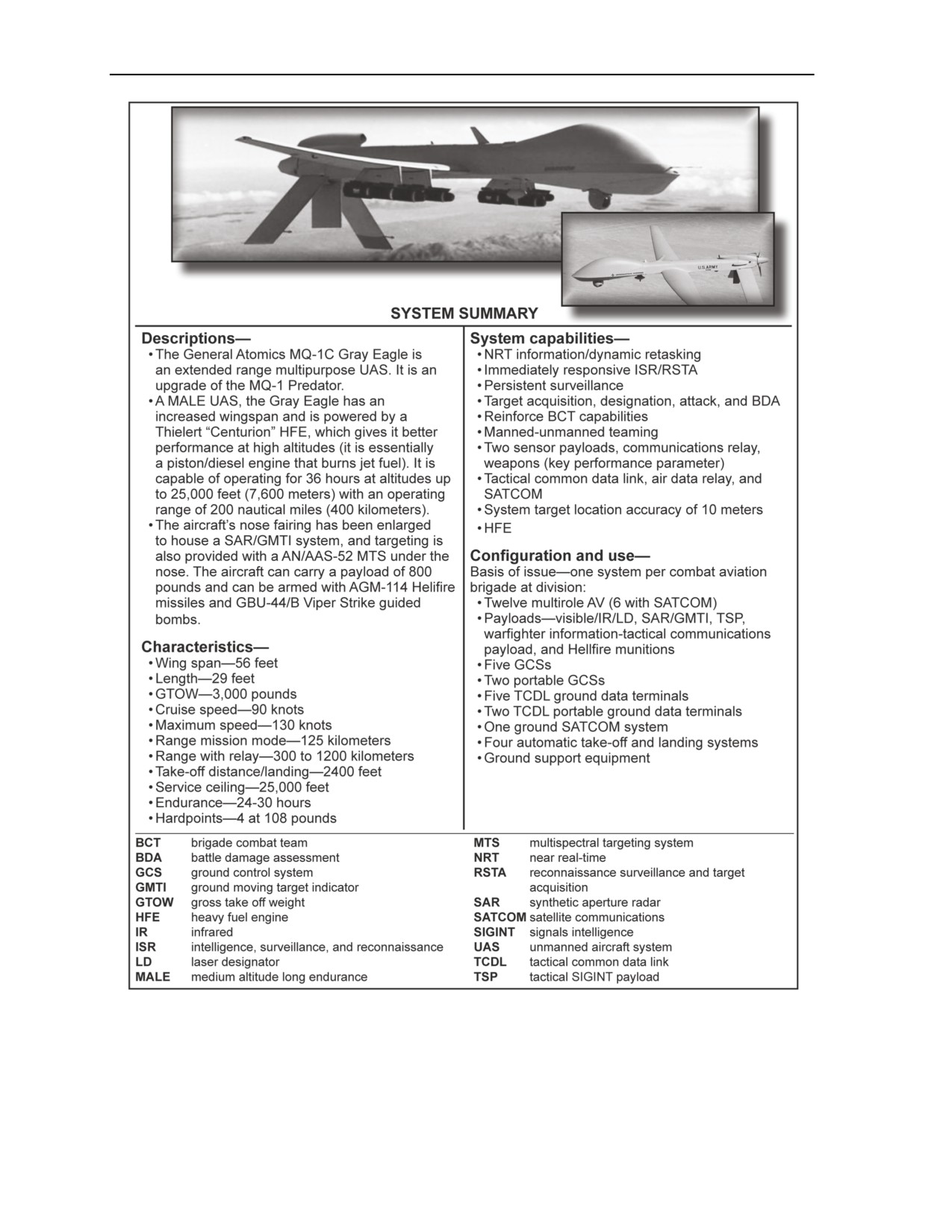
MQ-1C Gray Eagle, division. (See figure 2-11, page 2-18.)
z
MQ-5B Hunter, corps or higher. (See figure 2-12, 2-19.)
z
Warrior Alpha, corps or higher. (See figure 2-13, page 2-20.)
z
MQ-9 Reaper, corps or higher. (See figure 2-14, page 2-21.)
z
RQ-4A Global Hawk, corps or higher. (See figure 2-15, page 2-22.)
18 February 2011
TC 2-22.7
2-15
FOR OFFICIAL USE ONLY

Chapter 2
Figure 2-9. RQ-11B Raven UAS
2-16
TC 2-22.7
18 February 2011
FOR OFFICIAL USE ONLY

Imagery
Figure 2-10. RQ-7B Shadow UAS
18 February 2011
TC 2-22.7
2-17
FOR OFFICIAL USE ONLY
Chapter 2
Figure 2-11. MQ-1C Gray Eagle UAS
2-18
TC 2-22.7
18 February 2011
FOR OFFICIAL USE ONLY

Imagery
Figure 2-12. MQ-5B Hunter UAS
18 February 2011
TC 2-22.7
2-19
FOR OFFICIAL USE ONLY

Chapter 2
Figure 2-13. Warrior Alpha UAS
2-20
TC 2-22.7
18 February 2011
FOR OFFICIAL USE ONLY

Imagery
Figure 2-14. MQ-9 Reaper UAS
18 February 2011
TC 2-22.7
2-21
FOR OFFICIAL USE ONLY

Chapter 2
Figure 2-15. Global Hawk UAS
2-22
TC 2-22.7
18 February 2011
FOR OFFICIAL USE ONLY
Imagery
HANDHELD IMAGERY
2-36. Handheld imagery is a source of imagery collection consisting of digital images (photographs or
video tape) obtained through individual sources, for example, ground reconnaissance or open-source
intelligence medium.
Note. For the purpose of this manual, handheld imagery does not include handheld or
clandestine photography taken by or on behalf of HUMINT collection organizations.
Ground Reconnaissance
2-37. Digital images of physical areas taken by ground forces can be used to provide additional details of
the terrain for general planning, ISR operations, and targeting. These images should be included in a unit’s
imagery product library.
Open-Source Intelligence
2-38. Digital images taken by news organizations, civil government, and other groups that post or store
images on the Internet can provide additional details supporting the development of GEOINT products.
IMAGERY RESOLUTION
2-39. Imagery is collected by aircraft- and satellite-based platforms. Some aircraft and ground-based
sensors can be configured to carry a variety of sensor packages. Each sensor has unique technical
capabilities that allow it to image geographic areas and resolve physical characteristics of objects and
scenes.
2-40. Resolution is a measurement of the smallest detail that can be distinguished by a sensor system under
specific conditions (JP 1-02). It is expressed in units of meters, submeters, feet, or inches depending on the
system and collection in question. The specific resolution of an image is set by unique collection
parameters for that image.
Note. The intelligence community tracks resolution in feet and inches while the Army converts it
to meters for reporting consistency.
2-41. Electro-optical systems collect imagery to satisfy a specified ground sample distance, which refers to
the specific measurement between two objects required for a sensor to distinguish two independent objects.
Ground sample distance measurements are limited to visible and IR collection systems.
2-42. Radar collections use the term impulse response to express similar measurements. While platform
positioning is critical to determine ground sample distance, it is irrelevant for radar. Radar impulse
response is determined by the energy transmitted and the strength of the returns.
2-43. The intelligence community typically uses the National Imagery Interpretability Rating Scale
(NIIRS) to quantify the quality or usefulness of imagery. NIIRS provides a common framework for
discussing the information potential of imagery and is a standardized measure of image interpretability.
Commercial satellite imagery also uses NIIRS.
2-44. Through a process referred to as rating an image, NIIRS is used to assign a numeric value (0-9) that
indicates the assessed interpretability of that image. The NIIRS concept provides a means to directly relate
the quality of an image to the interpretation tasks for which it may be used.
2-45. Further information concerning NIIRS is available—
z
Visible (NIIRS-V).
IR (NIIRS-I).
18 February 2011
TC 2-22.7
2-23
FOR OFFICIAL USE ONLY
Chapter 2
Radar (NIIRS-R).
Spectral (NIIRS-S).
z
z
2-46. Resolution may also be referred to as—
z
Spatial resolution—is expressed in terms of ground sample distance for electro-optical, and in
terms of impulse response (as feet and inches) for radar.
z
Radiometric resolution—describes how precisely a system can represent or distinguish
differences of intensity; it is usually expressed as a number of bits or a number of levels, for
example, 8 bits or
256 levels, which is typical of computer image files. The higher the
radiometric resolution, the better the subtle differences of intensity or reflectivity, at least in
theory. In practice, the effective radiometric resolution is typically limited by noise level, rather
than by the number of bits of representation.
z
Temporal resolution—is the frequency at which images are recorded. Temporal resolution for
motion imagery is expressed in frames per second.
z
Spectral resolution—describes the ability of a sensor to define finite wavelength differences.
The finer the spectral resolution, the narrower the range of the wavelength for a particular
channel or band.
z
Radiometric resolution—determines how finely a system can represent or distinguish
differences of intensity, and is usually expressed as a number of bits or a number of levels, for
example, 8 bits or 256 levels, which is typical of computer image files.
IMAGERY TYPES
2-47. There are two types of imagery:
z
Still imagery is an individual image of an object or location.
z
Motion imagery consists of a series of images collected in sequence at varying frames per
second.
STILL IMAGERY
2-48. Still imagery uses a variety of media to capture different levels and categories of information about a
specific object or location. Still imagery may be collected in one or more of the following media formats:
z
Panchromatic (visible).
z
IR.
z
Radar.
z
AGI, including spectral imagery (multispectral, hyperspectral, and ultra-spectral).
Panchromatic Imagery
2-49. A panchromatic or visible image is acquired with a sensor that is sensitive to all or most of the
visible spectrum. Panchromatic imagery is black and white, displayed as a grey scale image, and generally
has a higher resolution than IR or spectral imagery. Panchromatic imagery has been the mainstay of IMINT
for years and continues to be an important source of IMINT data.
2-50. Imagery can be merged with other imagery data sources. One way is to merge panchromatic imagery
with multispectral imagery, commonly referred to as pan-sharpening. Pan-sharpening is a process that
fuses the color information from spectral imagery with the higher resolution of panchromatic imagery.
Normally the lower resolution bands (red, green, and blue bands) are fused with the panchromatic imagery,
producing a higher resolution (natural or true color) image. This process is also used to create a higher
resolution color IR image.
2-51. Controlled image base (CIB) and BuckEye are two examples of panchromatic imagery.
2-24
TC 2-22.7
18 February 2011
FOR OFFICIAL USE ONLY
Imagery
Controlled Image Base
2-52. CIB is a standard NGA digital imagery product produced to support mission planning and command,
control, communications, and intelligence systems. Other CIB uses include support to weapons systems,
regional overviews, and mapping where maps are nonexistent or outdated. CIB is panchromatic digital
imagery (see figure 2-16). It is a seamless, ortho-rectified image dataset from either stereo or mono NTM
or other adequate commercial source imagery.
2-53. Currently, CIB production is at one- and five-meter ground sample spacing, but legacy commercial
imagery remains available for areas that might not be covered by CIB. CIB is raster product format and
national imagery transmission format standard compliant. CIB uses World Geodetic System
1984
(WGS 84) datum and is distributed via classified NGA networks and via the Army supply system from the
Defense Logistics Agency on compact disk (CD)/digital video disk (DVD). CIB 5 is available for wider
areas of coverage and provides a level of detail approximately equivalent to a 1:50,000 scale map.
Figure 2-16. Controlled image base imagery
BuckEye
2-54. BuckEye was developed to satisfy a requirement for a field-expedient change detection system to
spot improvised explosive devices. Initial rotary-wing deployments to Iraq and Afghanistan collected color
imagery along transportation routes. BuckEye then evolved to an integrated electro-optical, digital
camera/light detection and ranging (LIDAR) system flown on fixed-wing aircraft. BuckEye imagery is
true-color, three-band imagery collected at resolutions around 10 centimeters. The individual image frames
are ortho-rectified using the LIDAR digital elevation model and mosaiced to form color imagery with
absolute accuracies under five meters. It gives Soldiers information through high-resolution color imagery,
GEOINT, elevation data, ISR, and detailed maps of urban areas of interest.
Infrared Imagery
2-55. IR imaging is used extensively for military and civilian purposes. Military applications include target
acquisition, surveillance, night vision, homing, and tracking.
2-56. Thermal imagery, including IR and OPIR, enables analysts to detect and identify activity based on
thermal and emissivity (radiance) signatures. IR imagery, not including the IR bands of spectral imagery, is
displayed as a gray scale image in which the different shades of gray represent the differences in
temperatures and emissivity of the objects in the image.
2-57. MWIR and LWIR are commonly used IR imagery subdivisions:
z
MWIR is best for most IR imagery and provides the greatest IR reflective and emissive data
with the highest spatial resolution for thermal imagery.
18 February 2011
TC 2-22.7
2-25
FOR OFFICIAL USE ONLY
Chapter 2
z
LWIR is the thermal imaging region in which sensors can obtain a completely passive picture of
the outside world based on thermal emissions only, requiring no external light or thermal source,
such as the Sun, Moon, or IR illuminator.
2-58. Some applications for IR imagery include—
z
Characterizing foliage.
z
Detecting camouflage.
z
Assessing crop health.
z
Determining the land-water boundary.
z
Analyzing coastal hydrography.
Radar Imagery
2-59. Radar imagery enables detection and identification of activity based on reflected radar energy. Due to
the active nature of the sensor, radar imagery can illuminate objects day or night and in every weather
condition. Processed radar data is depicted in a map-like format on the image. These characteristics enable
unprocessed or complex radar data to be used to collect and automatically detect motion within a single
radar image and to automatically detect change between two radar images. This ability promotes a radar’s
primary mission of change detection.
2-60. SAR systems propagate and collect radar energy the same as a real aperture system. However, SAR
systems record the returned energy to create a history of frequency shifts, known as a phase history, that
are reprocessed to create an image with consistent resolution, whether close to the sensor or farther away.
The tactical commander now has access to all-weather, day-night, and consistent resolution imagery to
compliment visible and IR sensor capabilities.
2-61. MTI is a radar capability that displays objects displaced from their actual location based on the speed
and direction of movement. MTI imagery can determine the direction and speed of objects, thereby giving
the commander better situational awareness of the AO.
Advanced Geospatial Intelligence
2-62. Advanced geospatial intelligence, also known as imagery-derived measurement and signature
intelligence, is technical, geospatial, and intelligence information derived through interpretation or analysis
using advanced processing of all data collected by imagery or imagery-related collection systems (JP 2-03).
2-63. AGI comprises the techniques used by geospatial engineers, imagery analysts, and imagery scientists
to process an image to look beyond the visual information depicted in the image. This process includes all
types of information technically derived from the processing, exploitation, and nonliteral analysis
(including integration or fusion) of spectral, spatial, temporal, radiometric, phase history, and polarimetric
data. These types of data can be collected on stationary and moving targets by visible, IR, radar, and related
sensor programs (both active and passive). AGI also includes ancillary data needed for data processing and
exploitation and signature information (including development, validation, simulation, data archival, and
dissemination).
2-64. Spectral imagery is collected by a series of sensors sensitive to specific wavelengths, usually
grouped in bands. By adding or subtracting the different bands, color imagery may be generated. Spectral
imagery is categorized into three groups that are distinguished mainly by the bandwidths and the number of
bands of the various spectral bands:
z
Multispectral imagery has a set of two to ten spectral bands with bandwidths or filters on the
order of ten’s of nanometers. One of the simplest examples of multispectral imagery would be a
color video camera consisting of three-band.
z
Hyperspectral imagery sensors, such as the aircraft visible/IR imaging spectrometer (AVIRIS)
project, have around 200 or more narrow spectral bands.
z
Ultra-spectral imagery possesses very fine spectral bandwidths of 1000 or more.
2-26
TC 2-22.7
18 February 2011
FOR OFFICIAL USE ONLY
Imagery
2-65. Spectral imagery collects multiple spectral bands across the electromagnetic spectrum to sense
reflective and emissive values of matter within a scene. The higher the resolution of the spectral band, the
more capable the sensor is to identify specific objects, such as rock or soil types, camouflage net
manufacturers, and vegetation. This capability and the creation of reflectance value (signature) libraries
provide additional signatures that allow imagery analysts to identify a wider range of activities, such as
distinguishing between real aircraft and decoys, characterizing substances of various types of emissions,
and detecting vehicles based on their unique signatures.
MOTION IMAGERY
2-66. A motion imagery system, as defined by the Motion Imagery Standards Board, is any imaging system
that collects at a rate of one frame per second (one hertz) or faster, over a common field of regard. This
explicitly includes but is not limited to electro-optical, IR, multispectral, and hyperspectral systems.
Note 1. Video teleconference, video telemedicine, and video support services applications do not
fall within the purview of the Motion Imagery Standards Board and are not subject to its
requirements.
Note 2. The Motion Imagery Standards Board makes no formal distinction between the terms
motion imagery and FMV. However, motion imagery must contain metadata. Some entities call
video with no metadata FMV. Historically, however, FMV has been that subset of motion
imagery at television-like frame rates (24-60 hertz).
2-67. Motion imagery frame rates are normally expressed in frames per second and the frequency must be
sufficient to show the desired motion. While FMV is the common term for motion imagery, it is normally
considered to be FMV when it has a temporal or time resolution of 30 or more frames per second.
2-68. Motion imagery sensors may be visible, IR, or complex waveforms based on radar imaging.
Collection of motion imagery, from a sensor mounted on aircraft platforms with long mission endurance,
allows imagery analysts to monitor high-interest activities in the operational environment, to include
tracking moving, fleeting, and emerging targets. Near real-time FMV also allows observation of rapidly
developing events and is a valuable tool for ongoing operations.
2-69. Motion imagery provides commanders a valuable tool for ongoing operations and persistent
surveillance. Motion imagery, as with still imagery, is collected in various portions of the electromagnetic
spectrum.
SENSOR TYPES
2-70. Imagery sensors collect and display data as either a fixed target indicator or MTI. Each sensor and
platform has a unique capability, with distinct advantages and disadvantages. The requirements manager
must understand each sensor and platform capability in order to select sensors and platforms that best meet
the requirements, thus enabling the analyst to answer intelligence requirements and the user to receive
quality intelligence. Appendix C provides a matrix of sensor characteristics.
2-71. There are two types of imagery sensors—passive imagery sensors and active imagery sensors. All
forms of image and nonimaging sensing occur through an interaction between some form of
electromagnetic energy (natural or manmade) and the object being observed.
PASSIVE IMAGERY SENSORS
2-72. Passive imagery is the collection of reflected or emitted electromagnetic energy from objects in the
imaged area. The sensor functions only in a receive mode and is therefore “silent.” Passive imagery sensor
types include panchromatic (visible), IR, and spectral (multispectral, hyperspectral, and ultra-spectral)
imagery. Passive imagery sensors use natural electromagnetic energy sources, such as the Sun, naturally
occurring radiation, or objects that generate their own heat (the object is burning energy).
18 February 2011
TC 2-22.7
2-27
FOR OFFICIAL USE ONLY
Chapter 2
ACTIVE IMAGERY SENSORS
2-73. Active imagery includes a growing range of sensing capabilities that broadcast energy and process
the returning energy in order to image a targeted area. Radar and LIDAR are the primary examples of this
type of imagery.
2-74. Active imagery sensors generate the electromagnetic (manmade) energy needed to “illuminate” the
object that is being imaged. Active imagery sensing capabilities include—
z
High-resolution radar imagery.
z
SAR.
z
Interferometric synthetic aperture radar (IFSAR).
z
MTI.
z
LIDAR laser imaging systems, which serve as a powerful complement to standard spectral
imagery.
2-28
TC 2-22.7
18 February 2011
FOR OFFICIAL USE ONLY
Chapter 3
Imagery Intelligence
IMINT is one of three components of GEOINT, as defined in chapter 1. This chapter
discusses the key role of IMINT:
• Requirements management.
• Echelons of IMINT production.
• Support to commanders.
• Other support.
• Imagery-related products.
ROLE
3-1. IMINT provides concrete, detailed, and precise image-based information on the location and physical
characteristics of the threat and the environment. It is a source of information to discern key terrain
features, installations, and infrastructure used to build intelligence studies, reports, and target folders.
3-2. IMINT assists commanders in applying and protecting their combat power. It supports the
commander’s decisionmaking by reducing uncertainty about the hostile situation and the surrounding
environment, providing situational understanding of natural and manmade terrain features. IMINT allows
the commander to see the AOs in near real-time, as the mission progresses. Additionally, IMINT facilitates
the IPB process and development of IPB products.
IMAGERY REQUIREMENTS MANAGEMENT
3-3. Imagery requirements management ensures the effective and efficient employment of collection,
processing, exploitation, and reporting resources to meet the commander’s need for intelligence. It is the
entire process—beginning with the translation of intelligence requirements into data collection, processing,
exploitation, and reporting activities. To meet the requirements, the GEOINT cell collaborates with the
collection management cell to ensure GEOINT requirements are tasked for collection or requests for
imagery are submitted to higher headquarters.
Note. The imagery requirements management process is described in this chapter as it pertains to
IMINT. Requirements management is not IMINT-specific; it pertains to all facets of GEOINT.
3-4. Requests for information (RFIs) are handled using organic assets or forwarded to higher or lateral
levels that may or may not be an Army unit. This allows for more systems with slightly different
capabilities.
3-5. The intelligence staff performs research within the intelligence database to determine whether the
needed information is already available. Retrieval or transfer of the information may be restricted by
requests that are more urgent. The intelligence staff should not bypass the database to save time in
processing an urgent request, since the information may have already been requested. Tasking duplication
wastes assets. The needed information may be available at a higher echelon and can be obtained by
submitting an RFI.
18 February 2011
TC 2-22.7
3-1
FOR OFFICIAL USE ONLY
Chapter 3
3-6. If the information is unavailable, the staff—
z
Validates the collection requirement.
z
Assigns a collection priority. (Prioritization ensures analysts get the most important data first.)
z
Checks current collection taskings to ensure organic assets have not already gathered the needed
information.
z
Assigns the intelligence requirement to organic collection assets, which—
Ensure a timely response to the request.
Allow for issuance of clear tasking instructions.
Lighten the burden on higher echelon assets.
3-7. If existing data or organic assets cannot satisfy a valid intelligence requirement, the intelligence staff
generates a collection requirement or request for data support. This can take advantage of the increased
capabilities at higher echelons. Requests should be as specific as possible to allow higher echelons to task
suitable resources against the requirement. Although unique situations and requirements may necessitate
specific assets or platforms
(because the product or information requirement only defines the need),
particular platforms or sensors are NOT specified by the request.
3-8. Although the joint architecture provides infrastructure for intelligence support, it is not solely
hierarchical. Formal command and control relationships exist to facilitate RFI management and optimize
complementary intelligence functions. They are configured by echelon but do not obstruct the timely flow
of critical intelligence up, down, or laterally. National agencies maintain systems and organizations that
respond directly and provide intelligence to any echelon for time-sensitive reporting. The format flow for
intelligence up and down echelons is through the National Military Joint Intelligence Center.
3-9. Imagery personnel within the Army G-2 staff’s requirement and intelligence support branches—
z
Assist in the management of theater-strategic intelligence activities.
z
Track RFIs.
z
Maintain situational awareness for the theater of operations.
z
Exploit near real-time imagery.
z
Produce IMINT products to support Army planners, decisionmakers, and the supported JFC’s
joint operations area.
IMAGERY TASKING
3-10. Imagery tasking is the process by which an imaging requirement is validated, prioritized, and
submitted for collection.
3-11. Requirements managers first determine whether the imagery requirement can be met by using
existing data or products. If new collection is needed, a formatted requirement is generated and submitted
to an intelligence collection manager for further processing. Imagery requirements processing falls under
one of three tasking options:
z
National-level tasking.
z
Commercial tasking.
z
Aircraft tasking.
NATIONAL-LEVEL TASKING
3-12. Requirements may be submitted for national-level tasking through the Geospatial Information
Management System (GIMS) (formerly the Requirements Management System). This system is the only
requirements management system used for tasking NTM.
3-13. Validated imagery requirements for NTM are processed through a departmental requirements officer
to de-conflict and prioritize requirement requests from other combatant commands, Services, and national
3-2
TC 2-22.7
18 February 2011
FOR OFFICIAL USE ONLY
Imagery Intelligence
agencies. The officer then coordinates with NGA to determine the requirements prioritization and
collection method.
3-14. Combatant commands use local collection or requirements managers to consolidate, prioritize, and
coordinate imagery requirements before going through a departmental requirements officer or responsible
agency for NGA-licensed commercial imagery.
COMMERCIAL TASKING
3-15. GIMS is also the tasking system for commercial systems. GIMS provides an integrated geospatial
view of NGA production operations and source holdings with the ability to manage the acquisition and use
of national and commercial imagery.
3-16. Commercial tasking requirements are approved through a path similar to national-level tasking.
NGA, the functional manager for GEOINT, validates and authorizes new commercial imagery collection.
AIRCRAFT TASKING
3-17. The tasking system used for aircraft assets is called the Planning Tool for Resource, Integration,
Synchronization, and Management (PRISM). PRISM is the core mission-planning tool for collection
management mission applications. It is a Web-based application that provides users, at the theater level and
below, the ability to integrate imagery assets with theater collection requirements. PRISM is also the
tasking system for DOD ISR satellites, such as the Operational Responsive Space-1 (ORS-1).
3-18. Aircraft collection requirements are approved by the collection management authority. The collection
management authority—
z
Establishes, prioritizes, and validates theater collection requirements.
z
Establishes sensor tasking guidance.
z
Develops theater collection plans.
3-19. Although the collection management authority normally resides at the combatant command, it can be
delegated to a subordinate task force as required.
Note. While PRISM is a primary requirements management tool, it is not the only means of
aircraft tasking. Other avenues may be as simple as word-of-mouth, chat, or standard message
traffic.
IMAGERY INTELLIGENCE PRODUCTION
3-20. IMINT production and products are typically separated into four levels:
z
National strategic level.
z
Theater strategic level.
z
Operational level.
z
Tactical level.
NATIONAL STRATEGIC LEVEL
3-21. National strategic-level IMINT supports the President, Congress, Secretary of Defense, and senior
military commanders. These IMINT products are used to—
z
Develop national strategies and policy.
z
Monitor international situations.
z
Prepare strategic estimates and strategies to prepare military plans.
z
Determine major weapons systems and force structure requirements.
z
Conduct strategic operations.
18 February 2011
TC 2-22.7
3-3
FOR OFFICIAL USE ONLY
Chapter 3
THEATER STRATEGIC LEVEL
3-22. Theater strategic-level IMINT supports joint operations by identifying current threat capabilities that
could affect national security and U.S. or multinational interests. Theater strategic-level IMINT includes
determining when, where, and in what strength a potential threat will stage and conduct theater-level and
strategic-unified operations.
OPERATIONAL LEVEL
3-23. Subordinate JFCs and their component commanders are the primary users of operational-level
IMINT. Operational-level IMINT focuses on threat military capabilities and intentions and assists JFCs and
component commanders in keeping abreast of events within their area of interest. IMINT assists
commanders in determining when, where, and in what strength the threat might stage and conduct major
operations. During counterinsurgency and counterterrorism operations, operational-level IMINT is
increasingly concerned with stability operations and has a greater focus on political, economic, and social
factors.
3-24. Operational-level IMINT—
z
Addresses operational themes from peacetime military engagement to major combat operations.
z
Facilitates the accomplishment of theater strategic objectives.
z
Supports the planning and conduct of joint and subordinate operations.
z
Focuses on providing commanders the information required to locate threat centers of gravity.
z
Provides relevant, timely, and accurate intelligence and assessments.
z
Includes monitoring terrorist incidents and natural or manmade disasters and catastrophes.
TACTICAL LEVEL
3-25. Tactical-level IMINT is used by commanders, planners, and operators for conducting full spectrum
operations. Relevant, accurate, and timely tactical-level IMINT allows tactical units to achieve positional
and informational advantage over their threats. Tactical-level IMINT critically focuses on providing
products that support IPB—detecting the presence of threat (and natural) obstacles, determining their types
and dimensions, and providing necessary information to plan appropriate bypass, combined arms breaching
or clearance operations to negate the impact on the friendly scheme of maneuver.
3-26. Tactical-level IMINT assists in identifying and assessing capabilities and vulnerabilities, as well as
describing the physical environment. It seeks to identify when, where, and in what strength the threat might
conduct tactical operations. Tactical-level IMINT is used to develop target packages and plan operations.
IMAGERY INTELLIGENCE-RELATED REPORTS AND PRODUCTS
3-27. Regardless of the Nation’s effective or sophisticated surveillance systems and organizations, or the
analyst’s expertise, if the imagery analyst cannot disseminate collected information in a usable form, its
value is wasted. Imagery analysis reports and products provide the imagery analyst with a simple, uniform
means of relaying intelligence information to the requesting agency. Each imagery analyst is required to
prepare the following reports and products.
IMAGERY INTELLIGENCE REPORTS
3-28. Imagery analysts record and disseminate analysis results to the intelligence community via IMINT
reports. Reports may be directly requested or used as a data-input vehicle for maintaining intelligence
databases, such as the Imagery Exploitation Support System (IESS), the National Exploitation System, or
the Modernized Integrated Database. Sample IMINT reports are listed in table 3-1.
3-4
TC 2-22.7
18 February 2011
FOR OFFICIAL USE ONLY

Imagery Intelligence
Table 3-1. Sample imagery intelligence reports
IMAGERY INTELLIGENCE PRODUCTS
3-29. IMINT products are concisely constructed visual packages of intelligence information that show how
a requirement has been satisfied. While the base elements of IMINT products may be similar, the specific
details are unique, addressing the requirement that drove its creation. Sample IMINT products are listed in
table 3-2, page 3-6.
18 February 2011
TC 2-22.7
3-5
FOR OFFICIAL USE ONLY

Chapter 3
Table 3-2. Sample imagery intelligence products
IMAGERY INTELLIGENCE IN THE JOINT ENVIRONMENT
3-30. The modern operational environment demands the Army to be a team within—
z
A joint team (for example, the Navy and USAF).
z
A multinational team (for example, England and Saudi Arabia).
z
An interagency team (for example, the CIA, NSA, and the NGA).
3-31. Under current conditions, no Service has the capability to win a war alone. Similarly, only in
exceptional circumstances can one Service successfully address the demands of any modern military
operation. This team concept involves every aspect of intelligence operations, including IMINT.
3-32. The joint intelligence architecture interconnects collectors, producers, and customers in an
information network. It provides a dynamic and flexible structure for global access to information from all
intelligence sources, at all echelons. All intelligence made available to the network from any source is
stored and communicated as data—as a text file, graphic, imagery, or other formatted information. The data
with associated metadata is stored on standards-compliant file servers that interface with the
communications network.
3-33. The joint intelligence architecture facilitates support to the JFC and subordinate joint force
components via the defense intelligence community and integrates any required support from nondefense
agencies and nongovernmental organizations. The architecture is configured to provide baseline data
needed to support joint operations and establishes a common means to provide theater and tactical
commanders a full range of intelligence, as required for operations. In joint operations—
z
The intelligence directorate of a joint staff (J-2) establishes collection requirements to meet
operational objectives.
z
The operations directorate of a joint staff (J-3) selects, assigns, and employs collection assets to
fulfill requirements.
z
The intelligence staff has a number of methods to satisfy combat information or intelligence
requirements. The staff follows basic principles in a series of sequential actions to answer
information needs.
3-6
TC 2-22.7
18 February 2011
FOR OFFICIAL USE ONLY
Chapter 4
Geospatial Information
Geospatial information is one of three components of GEOINT, as defined in
chapter 1. Geospatial information provides the necessary foundational data to satisfy
the commander’s and staff’s need to see and comprehend the operational
environment. This chapter focuses on—
• Geospatial engineering support to
• Geospatial data management.
operations.
• Data sources.
• Integrating geospatial support.
• Terrain-related products.
GEOSPATIAL INFORMATION AND SERVICES
4-1. JP 2-03 refers to geospatial information and services as the collection, information extraction,
storage, dissemination, and exploitation of geodetic, geomagnetic, imagery (both commercial and national
source), gravimetric, aeronautical, topographic, hydrographic, littoral, cultural, and toponymic data
accurately referenced to a precise location on the Earth’s surface. Geospatial services include tools that
enable users to access and manipulate data, and also include instruction, training, laboratory support, and
guidance for the use of geospatial data.
4-2. Tactically, within the Army, GI&S is the responsibility of geospatial engineers in their mission to—
z
Better understand the physical environment.
z
Provide a geospatial foundation for situational awareness and the COP.
z
Improve understanding of capabilities and limitations for friendly forces as well as the threat,
and highlight other conditions of the operational environment.
GEOSPATIAL ENGINEERING
4-3. Geospatial engineering refers to those engineering capabilities and activities that contribute to a clear
understanding of the physical environment by providing geospatial information and services to
commanders and staffs. Examples include terrain analyses, terrain visualization, digitized terrain products,
nonstandard tailored map products, precision survey, geospatial data management, baseline survey data,
and force beddown analysis (JP 3-34).
4-4. Geospatial engineers also exploit geospatial information and produce spatially accurate products for
measurement, mapping, visualization, modeling, and all types of analysis of the terrain. To better
understand the physical environment, geospatial engineers perform four major functions—generate,
analyze, manage, and disseminate—that are driven by or based on requirements (for more information on
geospatial engineer functions and activities, see ATTP 3-34.80):
z
Generate, acquire, extract, and fuse timely, relevant, and accurate multiresolution geospatial and
weather information to provide the appropriate data sets to the ABCS.
z
Analyze data, aided by computer algorithms and terrain reasoning tools, to enable prediction and
provide actionable information for decisionmaking.
z
Manage, update, and maintain a standard and sharable geospatial foundation to facilitate the
COP for the warfighter at all echelons.
z
Disseminate geospatial data updates to and from ABCS to maintain the COP and distribute
geospatial information to the appropriate level to facilitate operations.
18 February 2011
TC 2-22.7
4-1
FOR OFFICIAL USE ONLY
Chapter 4
GEOSPATIAL INFORMATION
4-5. Geospatial information identifies the geographic location and characteristics of natural or
constructed features and boundaries on the Earth, including statistical data and information derived from,
among other things, remote sensing, mapping, and surveying technologies; and mapping, charting, geodetic
data related products (JP 2-03). Geospatial information is the foundation upon which all other information
about the physical environment is referenced to form the COP.
4-6. Geospatial information is categorized as—
z
Geospatial data, which enables the foundation of the COP, includes—
NGA feature or vector data derived primarily from the Geospatial Intelligence Feature
Database (GIFD) and the Army’s Theater Geospatial Database (TGD).
Scanned digital map displays, including compressed arc-second raster chart (ARC) digitized
raster graphics, the future enhanced compressed raster graphic, and BuckEye imagery.
Elevation data, including digital terrain elevation data, LIDAR, and IFSAR.
Ortho-rectified imagery, including CIB, future enhanced compressed raster imagery (ECRI),
commercial imagery, and NTM.
z
Terrain data describes natural and manmade features—how they change over time, with use,
and under varying weather conditions. Terrain and weather factors profoundly influence
operations by directly affecting the physical environment and capabilities and performance of
Soldiers, equipment, and weapons systems.
TERRAIN VISUALIZATION
4-7. Terrain visualization involves portraying and interpreting the terrain and understanding its impact on
the situation. This impact affects friendly and threat capabilities. Geospatial engineers at every echelon are
considered terrain-visualization experts; as such, they visually present terrain-related relevant information
to commanders and staffs to help them conceptualize important aspects of the physical environment in
order to support decisionmaking. Advanced technology provides geospatial engineers the capability to use
and combine geospatial data to create interactive, dynamic, and customized visual products.
SUPPORT TO GEOINT
4-8. Geospatial engineering support to GEOINT includes the standards, processes, Soldiers, and
equipment to enable understanding of the physical environment. Geospatial engineers maintain an
enterprise geospatial database where geospatial data is compiled from multiple sources, including the NGA,
AGC, other Services, other federal agencies, and multinational partners. Geospatial data is also compiled
by exploiting new collection and production from deployed Soldiers and sensors.
4-9. Geospatial engineering also provides geospatial information that is not intelligence-related:
z
Safety of navigation products provided by the National Oceanic and Atmospheric Association
(NOAA) to support—
The MDMP.
Installation maps.
GI&S related to master real estate planning and range management.
z
Geospatial data for training, modeling, and simulations.
SUPPORT TO SITUATIONAL UNDERSTANDING
4-10. Geospatial information that is timely, accurate, and relevant is a critical enabler throughout the
operations process. Geospatial engineers, engineer coordinators, and other staff members—
z
Assist in analyzing the meaning of activities.
z
Significantly contribute to anticipating, estimating, and warning of possible future events.
4-2
TC 2-22.7
18 February 2011
FOR OFFICIAL USE ONLY
Geospatial Information
z
Provide the foundation for developing shared situational awareness.
z
Improve understanding of capabilities and limitations for friendly forces as well as the threat,
and highlight other conditions of the operational environment.
4-11. Geospatial engineers adjust their analysis as the commander’s intent is refined and more information
on potential missions is available.
INTEGRATING GEOSPATIAL SUPPORT
4-12. Successful integration of geospatial support focuses on providing the right information to the right
person at the right time. Throughout the operations process (plan, prepare, execute, and assess), the four
major functions of geospatial engineering (generate, manage, analyze, and disseminate) are performed (see
table 5-2, page 5-3) continuously to—
z
Describe the physical environment and the military significance of the terrain.
z
Facilitate the staff’s analysis of the operational environment.
z
Support situational understanding.
z
Enable decisionmaking.
PLAN
4-13. Planning begins with analysis and assessment of the conditions in the operational environment. Most
of the geospatial engineering effort is integrated into the MDMP primarily through the IPB process.
Geospatial information requirements are generated in the form of RFIs. Geospatial databases are
established at the onset of planning and continuously updated and maintained through execution.
Geospatial engineers maintain the map backg1rounds used in the ABCS to minimize inconsistencies.
Analysis of the mission variables enables geospatial engineers to describe the physical environment and to
help the staff further its analysis of the operational environment. The resulting geospatial information is
systematically disseminated through ABCS and tactical networks to enable staff planning and the
development of running estimates. During the last step of the MDMP, geospatial information and terrain
products are distributed to the staff to assist them in preparing their annexes and other attachments.
PREPARE
4-14. Preparation creates conditions that improve friendly forces’ opportunities for success. Geospatial
engineering supports preparation by generating terrain visualization products, such as 3D fly-throughs and
perspective views from projected friendly unit positions, to allow commanders to create realistic scenarios
and facilitate mission rehearsal. Geospatial engineers analyze newly acquired geospatial data and manage
geospatial databases to support planning refinement by monitoring and integrating geospatial information
through ISR collection, RFIs, and reach. New and updated geospatial information and terrain products are
disseminated to enable mission planning, planning refinement, and execution.
EXECUTE
4-15. Execution is putting the plan into action. During execution, geospatial engineering focuses on
maintaining situational awareness, facilitating assessment, enabling decisionmaking, and promoting
responsiveness when implementing adjustments. Geospatial engineers respond to new geospatial
information requirements generated from the ongoing integrating processes. They maintain geospatial
databases and incorporate new or updated geospatial data, which they disseminate to the force. Through
analysis, geospatial engineers assist the staff in identifying and assessing variances between current
situations and forecasted outcomes. Geospatial engineers also ensure the availability of near real-time
geospatial information by maintaining common access databases.
18 February 2011
TC 2-22.7
4-3
FOR OFFICIAL USE ONLY
Chapter 4
ASSESS
4-16. Commanders, assisted by their staffs and subordinate commanders, continuously monitor and
evaluate the current situation and the progress of the operation and compare them with the concept of
operations, mission, and the commander’s intent. The COP and running estimates are primary tools for
assessing the operation. Running estimates provide information from the perspective of each staff section,
aiming to refine the COP. The geospatial engineering effort is managed to generate geospatial information
needed by the staff to accurately assess the situation.
4-17. To support assessment, geospatial engineers continue to maintain updated geospatial databases and
thereby assist in the sharing and flow of geospatial data and information. During assessment, geospatial
engineering focuses on helping staffs maintain their running estimates through terrain analysis that
highlights the impact of changes in the terrain due to natural and human influences. Geospatial engineers
disseminate relevant geospatial information and visualization products to staff sections, functional cells,
and working groups to help the staff evaluate the current situation and the progress of the operation.
INTEGRATING PROCESSES
4-18. FM 3-0 describes integrating processes used to synchronize operations throughout the operations
process. Geospatial engineering is applied across the warfighting functions (movement and maneuver,
intelligence, fires, sustainment, command and control, and protection) through various integrating
processes. Although IPB is primarily aligned with the intelligence function, its role within the MDMP
provides a link for applying geospatial engineering to each of the warfighting functions.
INTELLIGENCE PREPARATION OF THE BATTLEFIELD
4-19. The integration of geospatial engineering into the four steps of the IPB process requires coordination
and synchronization between the geospatial engineer, intelligence staffs, and higher, lower, and adjacent units.
Step One—Define the Operational Environment
4-20. Geospatial engineers identify gaps in the coverage and availability of geospatial data and information
for the AO and the area of interest. They analyze the factors of the physical environment in consideration of
the warfighting functions.
Step Two—Describe Environmental Effects on Operations
4-21. Geospatial engineering supports this step by describing to the staff the results of the analysis initiated
during step 1.
Step Three—Evaluate the Threat
4-22. Geospatial engineers concentrate their analysis and evaluation of the terrain’s effects based on
geospatial information requirements generated. They incorporate the results of ISR operations, RFIs, and
reach into their analysis and disseminate geospatial information to further the staff’s analysis. The use of
ISR operations, RFIs, and reach continues to augment geospatial engineers’ own analysis.
Step Four—Determine Threat Coarses of Action
4-23. Geospatial engineers provide geospatial information and terrain products that assist the staff in
defining courses of action (COAs). They describe how the terrain might encourage or discourage a
particular COA.
4-4
TC 2-22.7
18 February 2011
FOR OFFICIAL USE ONLY
Geospatial Information
TARGETING
4-24. Targeting is the process of determining what targets to attack to achieve the maneuver commander’s
desired effects. Geospatial engineering provides high-resolution geospatial data and products with a greater
degree of positional accuracy than topographic line maps.
Targeting Process
4-25. The targeting process is based on four functions—decide, detect, deliver, and assess (D3A). To
support the targeting process, geospatial engineers by—
z
Integrating mobility and suitability products.
z
Incorporating terrain effects.
z
Performing line of sight analysis.
z
Helping to update the high-payoff target list based on changes in the terrain due to natural or
manmade influence.
z
Managing and providing the standard and sharable geospatial foundation within ABCS.
z
Collaborating with imagery analysts to perform change detection.
Targeting Meetings
4-26. Targeting meetings focus and synchronize the unit’s combat power and resources toward finding,
tracking, attacking, and assessing high-payoff targets. Before the targeting meeting, the engineer
coordinator, the geospatial engineering technician, and the G-2/S-2 collaborate to—
z
Gather geospatial information on potential high-payoff target nominations and terrain factors on
location.
z
Provide geospatial information on weapons use.
z
Make recommendations for air tasking nominations.
z
Provide updates on terrain effects changes.
z
Be prepared to provide a restricted target list of geospatial information and products.
INTELLIGENCE, SURVEILLANCE, AND RECONNAISSANCE SYNCHRONIZATION
4-27. ISR operations contribute significantly to the commander’s visualization and decisionmaking. ISR
synchronization satisfies as many information requirements as possible through staff coordination and
RFIs. Geospatial engineering is integrated into ISR synchronization through ISR working groups, GEOINT
cells, running estimates, and the ISR synchronization process. Collaborating with geospatial engineers, the
engineer coordinator advises the G-2/S-2 and G-3/S-3 on the geospatial engineering and engineer
reconnaissance capabilities available and how best to use them. (See FM 3-34.170 for more information.)
Terrain analysis and evaluation of the terrain’s effects assist the intelligence staff in employing collection
assets that allow maximum effectiveness without exposing those assets to unacceptable risks.
GEOSPATIAL ENGINEERING WITHIN OTHER INTEGRATING PROCESSES
4-28. Geospatial engineering can also be integrated into the following processes:
z
Composite risk management.
z
Knowledge management.
Composite Risk Management
4-29. Composite risk management is an integrating process that occurs during all operations process
activities. The process entails identifying, assessing, and controlling hazards
(risks) that arise from
operational factors and balancing the risks with mission benefits. (see FM 5-19 for more information.)
Geospatial engineering—
18 February 2011
TC 2-22.7
4-5
FOR OFFICIAL USE ONLY
Chapter 4
z
Focuses on assisting the staff in visualizing and assessing the hazards associated with the
physical environment.
z
Can assist planners in determining the effectiveness of cover and concealment provided by
natural and manmade features along movement routes and within static positions.
z
Can create special-purpose maps and visualization products to assist leaders in communicating
their instructions.
Knowledge Management
4-30. Another integrating process is knowledge management. It is the art of gaining and applying
information through people, processes, and technology. Geospatial engineers apply knowledge
management to transfer their knowledge of the physical environment effectively through terrain analysis.
Geospatial engineering—
z
Breaks down geospatial stovepipes.
z
Provides multiple users with rapid accessibility and retrieval of relevant geospatial information
enabled through effective management of geospatial databases and the map foundation of the COP.
z
Facilitates a near real-time, collaborative information-sharing environment by exploiting
information systems, knowledge networks, and tactical web portals.
GEOSPATIAL DATA MANAGEMENT
4-31. The Army capitalizes on information-sharing capabilities enabled by ABCS to facilitate
decisionmaking. To be effective, ABCS relies on access to current, accurate, and common geospatial data
residing in shared, distributed geospatial databases to form the foundation of the COP.
DIGITAL GEOSPATIAL DATA
4-32. Metadata consists of data automatically generated by the collection device or entity at the time of
collection as well as additional data provided by analysts or users in the future. Metadata allows users to
search for products or data as well as obtain services. Metadata allows discovery services in two ways:
z
A simple search based on key phrases, dates, names, product and data types, and so forth.
z
Users permitted to set up alerts that are triggered when a product or data that meets their
predefined query is posted on the network. More common geospatial products are available
through web services using a thin-client approach.
THEATER GEOSPATIAL DATABASE
4-33. Gathering geospatial data from numerous sources and making it readily available to multiple entities
enables the foundation of the COP. The data used for the COP is maintained and managed through the
TGD by the geospatial planning cell (GPC) at the Army Service component command (ASCC) level. NGA
data is used to structure the baseline for the TGD, providing a common initial source for GPCs to manage
for their assigned theater of operations.
4-34. TGD data is stored and organized at four resolution levels or scales, reflecting those of the NSG’s
Topographic Feature Data Management. The TGD schema is currently Feature Attribute Coding Catalog-
based, it but will transition to the NSG Feature Data Dictionary. The four resolution levels or scales are—
z
Strategic. Generally equivalent to a 1:1,000,000 scale. Data have features associated with
standard NGA maps at this scale (such as NGA Vector Map (VMAP) Level 0).
z
Operational. Generally equivalent to a 1:250,000 scale. Newly extracted data must adhere to
NGA cartographic standards at this map level
(such as NGA VMAP Level 1, Feature
Foundation Data (FFD), and Planning Interim Terrain Data).
4-6
TC 2-22.7
18 February 2011
FOR OFFICIAL USE ONLY

Geospatial Information
z
Tactical. Generally equivalent to a 1:50,000 scale, but can range from 1:100,000 to a 1:10,000
scales (such as NGA VMAP Level 2, Vector Product Format [VPF] Interim Terrain Data
[VITD], and Interim Terrain Data [ITD]).
z
Urban. Any special products that are 1:10,000 scales or larger, such as NGA Urban VMAP or
the AGC’s Urban Tactical Planning Data.
GEOSPATIAL PLANNING CELL
4-35. As the central authority for all geospatial data within a specific theater of operations, GPCs ensure
the distribution of geospatial data to each corps within the area of responsibility. Each corps maintains its
version of the TGD with inputs from geospatial engineer teams at lower echelons. GPCs collect the
enriched data from each corps and evaluate, correct, update, and incorporate it into the ASCC TGD. Lastly,
GPCs provide updated data to NGA for inclusion in its national geospatial databases. (See figure 4-1.)
Figure 4-1. GPC providing updated data to NGA
4-36. Geospatial database development and maintenance is a continuous process and involves shared
responsibility by geospatial engineers at each echelon down to the BCT. GPC data-management sections
are responsible for the development and maintenance of the TGD. They assist geospatial companies and
geospatial engineer teams in acquiring data and constructing their respective databases. Responsibility for
original inputs to the TGD rests with each echelon as the data applies to their area of responsibility.
Therefore, GPCs coordinate with geospatial engineer teams across echelons to ensure a synchronized
geospatial data collection effort that is incorporated into the TGD to provide a common database for all users.
18 February 2011
TC 2-22.7
4-7
FOR OFFICIAL USE ONLY
Chapter 4
4-37. GPCs must coordinate with each other and develop coproduction agreements to reduce duplication of
effort and facilitate the management of geospatial data generation and collection activities within their
respective operational areas. Each GPC generally maintains data that is required for its operational area—a
TGD does not need to mirror every other TGD. If a GPC enters into a coproduction agreement with another
TGD, the validation and acceptance of data belongs with the TGD responsible for that theater of operations.
4-38. NGA may augment GPCs with geospatial analysts, cartographic analysts, and data stewards. This
support greatly enhances the management of the TGD and ensures the quality of data generated by GPCs
and subordinates meet national mapping accuracy standards for subsequent inclusion and redistribution in
NGA’s national and regional databases.
DATA SOURCES
4-39. The items covered in this section may reflect the same name as the sensor package that collects them.
For example, within an imagery analysis section, the image data collected by the LIDAR sensor is referred
to as LIDAR by the analyst. Therefore, the names in this section only refer to the image product available
for exploitation by the analyst.
INTERFEROMETRIC SYNTHETIC APERTURE RADAR
4-40. IFSAR is a system or process used to generate elevation data of the Earth’s surface by observing a
location from two separate positions with a SAR sensor.
LIGHT DETECTION AND RANGING
4-41. LIDAR is used by geospatial engineers to improve situational awareness, terrain visualization, and
mission planning. LIDAR is a remote sensing sensor that measures the properties of scattered light from the
surface of a given target to determine its range and intensity. This is useful for development of 3D imagery
and line of sight determination. (See figure 4-2.) LIDAR is an active sensor-like radar but uses laser light
pulses instead of radio waves. The reflections are called returns or postings and, given the position and
altitude of the sensor, distance measurements are then transformed into elevation values. LIDAR sensors
can be divided into scanning and nonscanning systems—both capable of 3D imaging.
4-42. LIDAR data can be used to analyze terrain features, such as vertical obstructions and buildings, or
gridded to create a high-resolution and high-accuracy surface model. LIDAR data can also be used as a
stand-alone product or as an accurate foundation for rectifying and draping high-resolution imagery.
4-43. LIDAR-derived elevation values are used to determine bare Earth surfaces and 3D feature extraction
of urban areas and vegetation. Images are typically displayed in “false-color” (colors that differ from the
human perception), which represents variations in elevation. LIDAR also supports automated feature
extraction of buildings and vegetation.
4-8
TC 2-22.7
18 February 2011
FOR OFFICIAL USE ONLY
Geospatial Information
Figure 4-2. LIDAR (with elevation tint)
FEATURE DATA
4-44. Feature data, also referred to as vector data, provides digital representations of natural or manmade objects
as points, lines, or polygons (such as wells, roads, and forests). Each feature can include embedded information
(attribution), such as bank heights for bodies of water, type of road surface, road width, and bridge load-bearing
classification. Fully attributed feature data can be used to perform automated terrain analysis.
DYNAMIC TERRAIN VISUALIZATION
4-45. Dynamic terrain visualization, for example fly-throughs, is created by fusing imagery and elevation
data, producing a dynamic, free flying environment to provide terrain visualization. It may also be used as
tactical decision aids to support planning and execution of military operations. Dynamic terrain
visualization can be displayed as urban environment overlays on high-resolution imagery or maps.
MOTION IMAGERY AS A PRODUCT
4-46. Video imagery systems collect and transmit, edit, store, archive, or disseminate digital video for real-
time, near real-time, or for other end-user product distribution. The most common FMV encountered by an
imagery analyst is the IMINT product of UAS platforms employed to support daily IMINT collection
activities. In contrast, motion imagery—anything less than standard FMV (30 frames per second)—is
associated with wide-area surveillance systems, typically collecting at two or six frames per second. Motion
imagery is usually exploited in a forensic mode and helps develop pattern of life activities for a target.
4-47. UAS imagery analysis can be used to create IMINT products, or the actual UAS FMV may be
disseminated to an end user for analysis or provided in combination with IMINT products. Strategic- and
theater-level FMV and motion-imagery collection platform data are disseminated to the NSG architecture
via the Community Airborne Library Architecture (CALA), a central repository for unexploited digital
aircraft imagery. Aircraft, still, and motion imagery are currently accessible through CALA to the greater
GEOINT community.
THREE-DIMENSIONAL MODELING CAPABILITY
4-48. The process of developing a mathematical representation of any 3D object via specialized software is
3D modeling capability. Models may be created automatically or manually. Manual models are created
similarly to fly-throughs or by extracting manmade features for display in a 3D environment. Imagery
organizations are capable of creating 3D models or finished products can be ordered through commercial
software products. These products are merged, high-resolution, satellite imagery and digital elevation
models that provide the user a rich interactive 3D viewing capability.
18 February 2011
TC 2-22.7
4-9
FOR OFFICIAL USE ONLY
Chapter 4
TERRAIN-RELATED PRODUCTS
4-49. Terrain analysis is described as the study of the terrain’s properties and how they change over time
with use and under varying weather conditions. Terrain analysis starts with the collection, verification,
processing, revision, and construction of source data. It requires the analysis of climatology (current and
forecasted weather conditions), soil conditions, and threat or friendly vehicle performance metrics. In short,
it transforms raw data into usable information. Terrain analysis is a technical process and requires the
expertise of geospatial engineer technicians, terrain data specialists, and geospatial engineers or GEOINT
specialists.
4-50. The geospatial engineer technician conducts the major portion of the terrain analysis, combining
extensive database information with reconnaissance results. GI&S teams collaborate closely with imagery
analysts to enhance terrain analysis and products. Geospatial engineers or GEOINT specialists have access
to geospatial information databases, such as those produced by NGA and GPCs, allowing automated
support of the terrain analysis process.
4-51. Geospatial engineer and geospatial analysis teams also collaborate closely with the G-2/S-2 to
exploit imagery and reconnaissance information and reports, as well as other all-source data collected by
the G-2/S-2, to supplement their standard terrain databases and provide direct support to the unit.
Computer-generated terrain applications offer two-dimensional (2D) or 3D terrain analysis capabilities.
These databases should be supplemented with a physical (leader’s) reconnaissance of the terrain in
question, when feasible. Automated terrain programs address but are not limited to such factors as—
z
Cross-country mobility.
z
Lines of communications—such as transportation, communications, and power.
z
Vegetation type and distribution.
z
Surface drainage and configuration.
z
Surface materials.
z
Subsurface (bedrock) materials.
z
Obstacles.
z
Infrastructures.
z
Flood zones.
4-52. Terrain analysis must include the effects of weather on the terrain. It must consider the existing
situation, as well as forecasted conditions that can occur during mission execution, and express the results
of evaluation of the terrain’s effects by identifying areas of the AO that favor, disfavor, or do not affect
each COA. Drawing conclusions about the terrain and weather assist the staff in evaluating the terrain for
areas best suited for friendly and threat—
z
Engagement areas directed against aerial and ground targets.
z
Battle positions.
z
Infiltration routes.
z
Exfiltration routes.
z
Avenues of approach.
z
Specific system or asset locations.
z
Observation posts.
z
Ambush sites or positions.
z
Conclusions about the effects of terrain, which are reached through two substeps:
Analyze the military aspects of the terrain.
Evaluate the terrain’s effect on military operations.
4-10
TC 2-22.7
18 February 2011
FOR OFFICIAL USE ONLY
Chapter 5
Army GEOINT Implementation
The proper application of GEOINT provides commanders with timely, relevant,
accurate, predictive, and tailored image-based intelligence to support operations.
GEOINT, one of the Army’s intelligence disciplines, is a critical part of Army
tactical, operational, and strategic planning and operations.
THE GEOINT CELL
5-1. GEOINT cells comprise geospatial engineers and imagery analysts. Combining these skill sets into
one cell facilitates a collaborative environment for geospatial engineers and imagery analysts to achieve
maximum development of GEOINT products. As a collaborative environment, GEOINT cells at each
echelon provide direct access to geospatial engineers’ and imagery analysts’ expertise. GEOINT cells
afford a synergistic approach by synchronizing efforts and reducing redundancy, while maximizing the
collaboration between geospatial engineers and imagery analysts in a centralized production location.
5-2. Army GEOINT cells provide commanders and staffs a more complete picture of the physical
environment and infrastructure of the operational environment.
5-3. GEOINT cells are not exclusive in terms of other military occupational specialties (MOSs) contributing
to GEOINT cell missions. Under the G-2/S-2/J-2 staff, multidiscipline intelligence (such as, all-source and
signals analysts) collaboration and integration enable the best GEOINT production and visualization. In
addition to assigned personnel, GEOINT cells may include other attached personnel, as required.
5-4. The Army national-to-theater regional and national AGI nodes are key GEOINT production partners
at the combatant command and national levels. The Army national-to-theater regional nodes have
transformed to totally integrate GEOINT capabilities, including IMINT, AGI, OPIR, and GI&S.
5-5. GEOINT cells coordinate between the G-2/S-2/J-2, G-3/S-3/J-3, and engineer coordinator.
Coordination for the GEOINT cells should include mission requirements. Echelon levels determine the size
and capabilities of their GEOINT cells and the duties and responsibilities of the GEOINT cell personnel.
5-6. At the ASCC level, GEOINT cells include AGI nodes or divisions as part of a larger Army AGI
federation. This NGA-funded federation of INSCOM and the United States Army Space and Missile
Defense Command/Army Forces Strategic Command production elements provides AGI support to their
respective combatant commands as well as federated support to other elements, as required. Production and
dissemination are controlled through the AGI and MASINT Reporting and Dissemination Service
(AMRDS)—a Web-based portal used for submitting requirements and disseminating finished products.
AMRDS provides—
z
Standardized and automated GEOINT handling and linkage for producers and consumers,
including—
GEOINT requirements and RFIs.
Report generation.
GI&S mapping.
Dissemination.
Customer feedback.
z
Other common tools for searching, viewing, and manipulating reported data to support mission
requirements.
18 February 2011
TC 2-22.7
5-1
FOR OFFICIAL USE ONLY
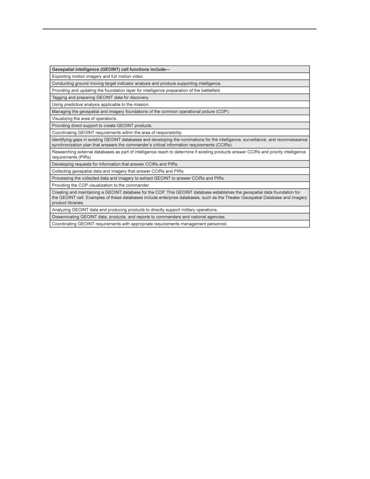
Chapter 5
5-7. Table 5-1, page 5-2, lists GEOINT cell functions.
Table 5-1. GEOINT cell functions
5-8. Future GEOINT cells may also incorporate or access commercial imagery and topographic
capabilities provided by Army space support teams and commercial imagery teams through their
commercial imagery data acquisition system.
GEOINT ACTIVITIES
5-9. The intelligence process provides a common model for intelligence professionals to guide their
thoughts, discussions, plans, and assessments. (See FM 2-0.) GEOINT operations follow similar steps and
activities of the intelligence process. However, GEOINT has several unique considerations used by Army
Soldiers and organizations.
5-10. Figure 5-1 depicts GEOINT activities. This sequence is continuous. The commander provides
guidance and focus to the activities through commander’s critical information requirements (CCIRs).
GEOINT activities support the mission by providing the required products that satisfy the CCIRs.
5-11. Table 5-2 is a correlation chart relating the imagery analyst’s TCPED process and the geospatial
engineer’s four primary functions (generate, manage, analyze, and disseminate) with GEOINT activities
illustrated in figure 5-1.
5-2
TC 2-22.7
18 February 2011
FOR OFFICIAL USE ONLY

Army GEOINT Implementation
Figure 5-1. GEOINT activities
Table 5-2. GEOINT activities correlation chart
18 February 2011
TC 2-22.7
5-3
FOR OFFICIAL USE ONLY

Chapter 5
PLANNING AND DIRECTION
5-12. The GEOINT planning activity includes planning for GI&S and imagery support. Direction refers to
the process of shaping and prioritizing the actions identified during planning to create a balanced GEOINT
collection requirement strategy. The combatant command GEOINT cell coordinates closely with the NSG
throughout the planning activity.
5-13. The GEOINT cell performs GI&S and imagery-related planning activities for the commander. The
GEOINT cell supports the operations and intelligence processes through the development of functional
support plans for GEOINT analysis and production.
COLLECTION
5-14. Information needs drive collection operations. GEOINT requirements necessitate the tasking and
collection of imagery, geospatial data, and completed products. Collection operations use satellites, manned
and unmanned aircraft, and reach to collect and derive new and existing collections.
PROCESSING AND EXPLOITATION
5-15. The imagery and geospatial communities possess exploitation capabilities for aircraft, overhead
imagery, and AGI to support operational requirements.
5-16. Raw data is received from collection platforms and processed into human readable formats for
exploitation and analysis. Once processed, geospatial data is distributed, archived, and made accessible to
users through various libraries and databases. The user can manipulate the data to create tailored products
or data sets for specific mission purposes or military applications.
5-17. Imagery exploitation involves the evaluation, manipulation, and analysis of one or more images to
extract information related to a list of essential elements of information. Exploitation information and
results are normally disseminated via a report. Imagery exploitation is managed through the IESS for DOD
organizations and by the National Exploitation System for NGA. Both systems perform numerous
functions, including—
z
Target management.
z
Requirements management.
z
Imagery ordering management.
z
Exploitation management.
5-18. Urgent information is expedited using the three phases (see table 5-3) of still imagery exploitation:
z
Phase 1—time-dominant.
z
Phase 2—time-dominant.
z
Phase 3—nontime dominant.
Table 5-3. Still imagery exploitation
5-4
TC 2-22.7
18 February 2011
FOR OFFICIAL USE ONLY

Army GEOINT Implementation
5-19. Motion imagery is also exploited via phases (see table 5-4):
z
Phase 1—rapid or near real-time call outs.
z
Phase 2—initial annotated stills and motion imagery clips (supplementary).
z
Phase 3—detailed analysis multi-intelligence fusion.
5-20. While these phases are similar to those described in table 5-3, they differ based on the media being
analyzed. The key differentiation is the dimension of time. Individual frames collected over time and
displayed in continuous sequence result in motion. Analysts perform phase 1 exploitation during this
continuous sequential display of the individual frames. For the remaining phases, analysts work from
imagery clips selected during phase 1.
Table 5-4. Motion imagery exploitation
ANALYSIS AND PRODUCTION
5-21. GEOINT products include traditional geospatial information and imagery-based products as well as
more advanced products created by combining GI&S and imagery data into a single, multidimensional
product. This activity provides the tactical commander with comprehensive, highly detailed, and precise
GEOINT products.
5-22. Once data has been processed, a variety of users can exploit it and produce either general intelligence
or mission-specific products. Data can also be combined in a variety of ways to develop tailored products
for specific mission requirements. Users or requesters of the intelligence should coordinate with the
producers to ensure the products meet mission needs. The main producers include Service exploitation and
production centers, NGA, DIA, and the combatant commands. At the combatant command and Service
levels, hydrographic and geospatial engineering units or sections—
z
Provide the ability to analyze integrated databases for specific applications.
z
Add valuable information or update features and attributes within the database.
z
Strengthen database content to meet the commander’s tailored mission requirements.
5-23. GEOINT products and related services and support are categorized as standard or specialized:
z
Standard GEOINT products are developed from visible, radar, IR, and multispectral sensor
data. These products may be simple—such as imagery read-outs, reports, maps (for example,
topographic line maps), and charts—or more complex products containing several layers of data
ranging from geographic to intelligence information. Traditional products are usually 2D but
may be created as 3D in certain circumstances.
z
Specialized GEOINT products use standard products as a foundation but provide added
capabilities. These products may be developed using data from multiple sources, multiple
intelligence disciplines, and advanced sensors. They may also include a fourth dimension (time)
that provides motion to create dynamic, interactive products. These products can include realistic
mission simulations that help determine the effects of currents, tides, wind, and daylight on a
mission or intelligence problem. Customized products also include products such as—
Two color multi-view.
Change detection.
18 February 2011
TC 2-22.7
5-5
FOR OFFICIAL USE ONLY
Chapter 5
Interactive maps to visually depict patterns and trends.
A visual to provide a common reference and rapid situational awareness for all personnel
and organizations involved in the same mission.
5-24. GEOINT products are often developed through a process known as “value added,” in which both the
producer and user of GEOINT update a database or product with current information. New roads,
obstacles, and seismic activity are examples of activities that require updating due to frequent changes.
Organizations (such as special forces and terrain teams or cells) may start with NGA products and add
tactical data of special interest for use by local commanders and operators. This specialized data is centrally
stored and catalogued.
DISSEMINATION
5-25. Dissemination is the timely distribution of GEOINT products in an appropriate form and by any
suitable means, whether in hardcopy or digital format. Dissemination is accomplished through the pull and
push principles:
z
The pull principle provides intelligence organizations at all levels with direct reach capability via
electronic access to central databases, intelligence files, or other repositories containing
GEOINT data and products.
z
The push principle allows the producers to transmit GEOINT to requesters along with other
relevant information. Typically, the intelligence staff element at each echelon manages the
dissemination of GEOINT.
GEOINT-Focused Dissemination Processes
5-26. Current GEOINT-focused processes disseminate GI&S, imagery, or imagery-related products. Single
dissemination processes are becoming increasingly common as GEOINT evolves. This publication
primarily addresses the more common processes used for separate dissemination of GI&S and imagery
derived products.
National Geospatial-Intelligence Agency Portals
5-27. NGA provides GEOINT data or products online via NGA portals that are accessible through the
NIPRNET, SIPRNET, and JWICS.
5-28. NGA can also support immediate deployment of personnel and equipment worldwide at any time
through remote GEOINT services (RGS):
z
The RGS team compiles custom GEOINT solutions for military and civilian missions through
direct customer interface. NGA sites in Maryland and Missouri serve as reach centers.
z
The RGS technical support team maintains the robust RGS equipment, including multiple
large-format plotters for mass quantity printing. Software includes a full suite of high-end GI&S
tools and image manipulation capability.
z
The RGS analytical team comprises employees with a unique combination of backg1rounds and
skills, including imagery analysts, cartographers, regional analysts, and geospatial analysts.
5-29. The Services have also developed dissemination capabilities that support standard NGA digital maps
and charts (USAF Geospatial Product Library) as well as attributed feature data (Army TGD).
Global Broadcast Service
5-30. Another dissemination system is the Global Broadcast Service (GBS). GBS can disseminate large
amounts of data in near real-time to a group of users or each user can pull a large file from the web-
accessed retrieval portal (WARP) via GBS. The Joint Warfare Analysis Center (JWAC) also maintains an
imagery library, the JWAC Warfighter Imagery Library (JWIL), which is accessible through queries on
WARP.
5-6
TC 2-22.7
18 February 2011
FOR OFFICIAL USE ONLY