Military reference books and manuals (2009-2023, Volume 6) - page 20
SUMMARY
During the course of this lesson you have learned that that through the studies of the histories of war that
success in battle is not always determined by the number of Soldiers or firepower. Success is more often
determined by the discipline and training of the Soldiers involved. This situation often applies to civil
disturbance control operations because our Soldiers can be expected to be greatly outnumbered. You have been
taught that through a system of crowd control formations that the numbers concerning the control force and the
demonstrators can be offset. By implementing and training what you have learned, you will continue to gather
more knowledge of these crowd control formations to assist you in effectively employing your Soldiers in a
civil disturbance operation.
Lesson 3 Practice exercise)
The following questions are multiple choice and/or true/false. You are to select the one that is correct. Show
your choice by CIRCLING the letter beside the correct choice directly on the page. This is a self-graded lesson
exercise. Do not look up the correct answer from the lesson solution sheet until you have finished. To do so
will endanger your ability to learn this material. Also, your final examination score will tend to be lower than if
you had not followed this recommendation.
1.
The normal cadence for movement into and assembly from all crowd control formation is
A. Route step.
B. Quick time.
C. Double time.
D. Any of the above.
1.
After breaking up a large crowd with crowd control formations
A. The control force should stand in place.
B. The control force is normally relieved of duty.
C. As many arrests as possible should be made.
D. Small groups of rioters may form.
1.
A formation used in order to apprehend a person surrounded by a crowd is the
A. Line.
B. Echelon left.
C. Diamond.
D. Wedge.
1.
Vehicles should always be used.
A. With foot Soldiers.
B. As a last resort.
C. In mass.
D. In pairs.
1. The following arm signal is for a.
A. Line formation.
B. Wedge formation.
C. Echelon formation.
D. Squad in support formation.
1.
The safe port position is
A. Extremely useful for a show of force.
B. Not useful because it cannot be seen at the rear of the crowd.
C. Used only to move away from crowd formations.
D. Easy to maintain over extended periods of time.
1.
The best formation to hold back a threatening crowd is the
A. Echelon.
B. Diamond.
C. Wedge.
D. Line
1.
When getting ready to use crowd control formations, it is best to
A. Assemble in full view of the crowd, but at a safe distance.
B. Form the desired formation and double time toward the crowd.
C. March in column formation to a safe distance from the crowd.
D. Use crowd control agents prior to assembly.
1.
The command used to form a squad into a line formation is
A. Extend to the right, Move.
B. Fall in on line, Move.
C. Squad Line Formation, Move."
D. Squad as skirmishers, Move.
1.
When in column, the commander at each echelon normally assumes his position
A. At the front of the column.
B. To the right of the column.
C. To the left of the column.
D. At the rear of the column.
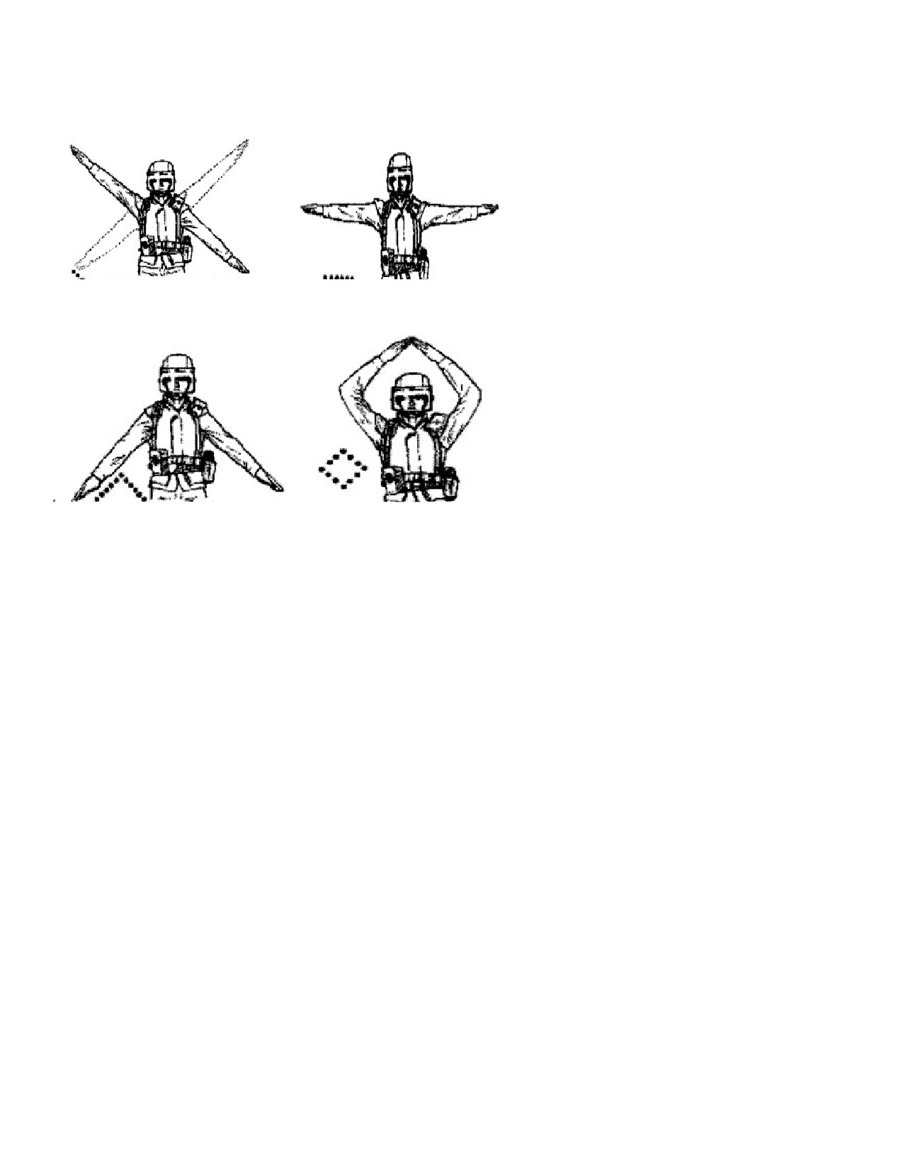
1. The hand signal for a line is
A
B
C
D
1. In any echelon formation with normal interval and distance, the angle made by the formation and the route
of advance will be approximately ____________.
A. 30 degrees.
B.
35 degrees.
C.
40 degrees.
D. 45 degrees.
1. What are the two base element ranks?
A. Shield holders, and nonlethal weapons.
B. Shield holders and baton holders.
C. Extraction and apprehension teams.
D. Riot control agent dispenser operations and squad leaders.
LESSON 3
PRACTICE EXERCISE
ANSWER KEY AND FEEDBACK
Item
Correct Answer and Feedback
1.
C.
Double time. (page 3-15)
2.
D.
Small groups of rioters may form. (page 3-4)
3.
C.
Diamond.
When Soldiers penetrate. (page 3-6)
4.
A.
With foot Soldiers. (page 3-5)
5.
B.
Wedge formation. (page 3-14)
6.
A.
Extremely useful for a show of force. (page 3-10)
7.
D.
Line. (page 3-6)
8.
C.
March in a column formation to a safe. (page 3-7)
9.
C.
Squad Line Formation, Move." (page 3-17)
10.
A.
At the front of the column.
When in a... (page 3-11, para 3a)
11.
B.
Figure 3-3 (page 3-14)
12.
D.
45 degrees (page 3-16)
13.
A.
Shield holders and NLW (page 3-6)
LESSON 4
RIOT CONTROL AGENT DISPERSER
OVERVIEW
LESSON DESCRIPTION:
This sub-course is designed to describe how agents are dispersed and required equipment maintenance.
TERMINAL LEARNING OBJECTIVE:
ACTION:
Maintain and operate riot control agent dispersers.
CONDITION: You will have this subcourse.
STANDARD: To demonstrate competency of this task, you must achieve a minimum score of 70 percent on
the final subcourse examination.
REFERENCES: The material contained in this lesson was derived from the following publications: FM 3-
19.15; FM 3-122.40.
INTRODUCTION
Crowd control agents provide us a distinct advantage in controlling civil disturbances and give us a
humane and effective method of dispersing dissidents. Crowd control agents have many advantages over other
types of force. They have an immediate effect on large groups of people without causing any permanent harm.
When conditions are favorable, these agents, properly used, will disperse large mobs without the control forces
actually making contact with the dissidents. To properly use crowd control agents, it is vital that you have a
thorough understanding of their capabilities, potential hazards, and methods of use. You must also be able to
properly operate the special items of equipment needed to disperse crowd control agents during a confrontation.
1. Crowd Control Agents.
a. CS. This agent is the current standard crowd control agent. Its application produces an extreme burning
sensation of the eyes, an abundant flow of tears, an involuntary closing of the eyes, a stinging sensation on
moist areas of the body, and other discomforting physiological symptoms. It may cause nausea and mild
vomiting if received in heavy concentrations (such as within a closed room), but no permanent injury will
result from the use of CS.
WARNING: BE AWARE THAT FIRES MAY START WHEN USING CS. REFER TO FM 4-
30.13, AMMUNITION HANDBOOK FOR SPECIFIC INFORMATION.
b. OC. More widely know as "Pepper Spray", OC is made completely from organic materials and is FDA-
approved for sale over-the-counter in the United States. It causes sever and immediate burning sensation to
mucous membranes when sprayed into face, nose, and eyes.
2. Methods of Disseminating Crowd Control Agents.
a. Individual Riot Control Agent dispenser (M36). The M36 (see Figure 4-1) contains a Dibenz (F, -1 4-
oxazepine [CR] solution). It can deliver 25 one-second bursts out to 12 feet. Individual disposable RCA
dispersers are intended primarily for self-defense or to keep rioters out of arm’s reach of Soldiers
conducting crowd control formations or Soldiers engaged in missions where a noncombatant exists.
FIGURE 4-1. Individual Riot Control Agent Dispenser (M36).
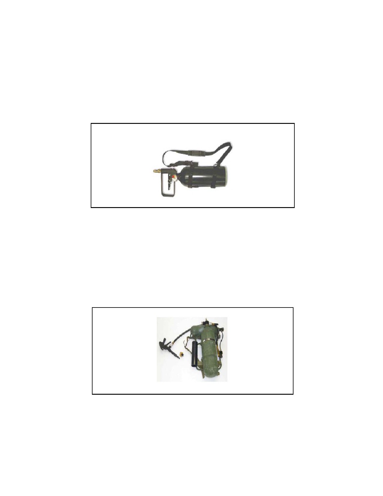
b. Midsize Riot Control Agent Dispenser (M37). The M37 (see Figure 4-2) is the size of a standard fire
extinguisher that uses compressed air to force the RCA out to a range of 30 feet. It has the capacity to
employ 18 bursts for 3 seconds per charge. It is excellent for providing a wide coverage of RCAs onto a
hostile crowd while maintaining excellent standoff capability. The M37 can be refilled and is rechargeable.
It can be filled with CR solution (liquid agent) or CS1 (dry agent). For training purposes, CR can be
substituted with water and CS1 can be substituted with talcum powder.
FIGURE 4-2. Midsize Riot Control Agent Dispenser (M37).
c. Squad Riot Control Agent Dispenser (M33A1). The M33A1 (see Figure 4-3) is designed to provide
crowd control and protection at the squad level. It is capable of projecting a ballistic stream of RCAs
beyond 25 feet in up to 25 half-second bursts. It consists of a frame and harness assembly, compressed-gas
cylinder (agent container assembly), air pressure assembly, gun and hose assembly, multijet spray unit, and
check valve assembly. The M33A1 can be refilled and is
FIGURE 4-3. Squad Riot Control Agent Dispenser (M33A1).
d. M7 66-Millimeter Launcher with M315 Installation Kit. The M7 (see Figure 4-4) is a 66-millimeter
vehicle-mounted, NL, grenade-launching device that is mounted on a HMMWV. It is an indirect fire support
system that can deliver the M98 distraction grenade that creates a flash-bang effect, L96A1 antiriot grenade, or
M99 blunt trauma grenade that creates a sting-ball effect. The M315 installation kit is used to install an M7
discharger on the turret ring of appropriate HMMWV variants. An adjustable bracket allows the launch angle

to be depressed for engaging targets at ranges of 50, 75, and 100 meters. The system enforces standoff
distances and deters potential threats.
FIGURE 4-4. M7 66-Millimeter Launcher with M315 Installation Kit.
e. L96A1, Grenade, Discharger, Antiriot Grenade. The L96A1 (see Figure 4-5) is a 66 millimeter projectile
that contains 23 canisters filled with CS compound. At a muzzle velocity of 35.8 meters per second (117.5 feet)
the projectile has a deployment range of 65 to 95 meters. The antiriot (CS) is released from the submunitions as
they burn on the ground.
FIGURE 4-5. L96A1, Grenade, Discharger, Antiriot Grenade
f. M203 grenade launcher. Using the CS round for the M203 grenade launcher, CS agent can be accurately
used against a point target at a range of 200-400 meters. Caution should be used not to fire the round
directly at a person as injury from the projectile as possible. The M47 CS round may also be hand dispersed
at a less effective range.
3. Principal Factors that will Govern the Employment of Crowd Control Agents.
a. To determine whether crowd control agents may be used effectively and how they can best be dispersed,
many factors must be considered.
(1) Effect of weather and terrain. After the crowd control agent has been released into the atmosphere, the
agent cloud will rise and drift downwind in a manner entirely dependent upon existing weather and terrain.
(2) Vertical rise. Agent clouds, which are a suspension of particles in the air, are initially warmer than air
and tend to rise rapidly. As these particles cool, they will subsequently settle back to earth.
(3) Lateral spread. Agent clouds will be blown from side to side by shifting air currents. As a general rule,
lateral spread is equal to about 15 to 20 percent of the distance traveled.
(4) Obstacles. Agent clouds will be disrupted by terrain obstacles, such as trees and buildings, and their
effectiveness reduced. As a general rule, an obstacle will disrupt an agent cloud for a downwind distance of
30 times the height of the obstacle.
(5) Favorable conditions. The downwind travel of agent clouds will be favorably affected by the conditions
listed below. The reverse of these conditions will, of course, adversely influence the performance of the
agent cloud.
(a) Steady wind direction.
(b) Moderate wind velocity (less than 10 mph).
(c) High relative humidity.
(d) Ground temperature colder than air temperature.
(e) Minimal obstacles, such as open areas, little vegetation, and no buildings.
b. Operational Objective. The manner of using crowd control agents will vary with the operational
objective being pursued. By varying the amount and method of use, different effects can be produced on the
crowd or mob.
(1) Dispersal. The most common usage of crowd control agents is to motivate hostile crowds to leave
the area. CS, applied in sufficient quantities by either grenades or dispersers, is usually highly effective.
Caution must be used and escape routes must be made available.
(2) Splitting a Crowd. When it becomes necessary to split a crowd, CS may be applied so as to produce
a narrow cloud through the center of the crowd. This will split the crowd for the duration of the agent
cloud's effectiveness.
(3) Deny Access to Area. When conditions warrant, access to an area may be denied by applying
micro-pulverized CS. The persistency of the agent, when mixed with the surrounding earth, vegetation,
or other material, will discourage the approach of unprotected personnel for the period of the agent's
effectiveness.
(4) Anti-barricade Operations. Where persons, such as snipers or other armed and dangerous persons,
are barricaded within buildings, crowd control agents may be invaluable in effecting their apprehension
with minimum danger to the control force and bystanders. When arrest teams are in position, M47
grenades may be applied, first in the surrounding area, then within the barricaded room itself.
c. Motivation of Dissidents. A thorough application of CS should be sufficient to convince most persons to
cease their disorderly conduct. However, riots or demonstrations have involved rioter or demonstrators that
are young, healthy, and most importantly, highly motivated. Such demonstrators have frequently been able
to withstand repeated dosages of crowd control agents, withdrawing from the agent cloud and returning
once the cloud dissipates. In such cases, application of crowd control agents alone is obviously not
sufficient to subdue the disorder; they must be followed by other measures such as selective or mass arrests.
4. Training.
a. Training of Soldiers for use of crowd control agents should include, but not be limited to, the following:
(1) Individual Training.
(a) Policy on the employment of crowd control agents.
(b) Characteristics of crowd control agents.
(c) Individual protection, first aid, and decontamination.
(d) Maintenance of crowd control agent munitions and equipment.
b. Unit Training.
(1) Crowd control agent squad organization.
(2) Tactical employment of crowd control agents in crowd control.
5. Operation and Employment of Crowd Control Agent Dispersers.
a. General. The following provides data and guidance for commanders, staff officers, and all personnel
concerned with the utilization of crowd control agent dispersers in the control and suppression of disorders.
It covers concepts and techniques for use of the crowd control agent dispersers and provides guidance for
the training of operating personnel.
b. Concept of Employment. The crowd control agent dispersers were developed to provide commanders
with a capability for distributing crowd control agents in sufficient quantities to provide effective area
coverage under a variety of situations and weather conditions. They are not designed for the direct
introduction of a crowd control agent into barricaded buildings. Care must also be exercised in their use in
confined areas and against target areas with restricted avenues of escape. Normal usage envisions transport
of these dispersers by persons, by 1/4-ton or larger vehicles, or by helicopters. When transported by the
ground, by individual or by vehicle, the dispersers may be directly integrated into crowd control troop
formations or may be operated from a position in direct support of confrontation control operations.
Dispersers mounted in helicopters are used in close conjunction with the control Soldiers and in direct
implementation of the immediate plan of operations. The exact location of the aircraft, with respect to troop
formation, at the time of release of crowd control agents will be determined by current wind direction and
speed, and in some instances by such physical obstacles as may place a restriction on the movements or
positioning of the aircraft.
c. Personnel.
(1) Although it is desirable that all unit personnel should have knowledge of the operation and
employment capabilities of the crowd control agent dispersers, main reliance in this respect must be
placed on specially selected and trained persons. Such personnel should be chosen for initiative, ability to
learn, and proven calmness when faced with large numbers of agitated people.
(2) Persons named as disperser operators and/or as team members should be well-qualified in their
primary MOS as members of the military police or other units authorized as dispersers, and thoroughly
trained in civil disturbance operations. Preferably they should have received special training in the use of
crowd control agents.
d. To ensure equipment is operational when it is needed, preventive maintenance and service must be
performed.
6. Authority and Limitations on the Use of Crowd Control Agents.
a. Experience and common sense have dictated some rules for the effective use of crowd control agents.
These rules, while not absolute, should be duly considered before using crowd control agents.
(1) Limitations.
(a) Do not use around hospitals or other places where innocent persons may be affected.
(b) Do not use around highways where drivers may be affected.
(c) Do not use where fires may start or asphyxiation may occur.
(d) Do not use where control forces may be unprepared and adversely affected.
(e) Do not use prior to coordinating with all agencies in the affected area.
(f) Do not use where a change in wind would cause harm or hamper control operations.
(g) Do not use where inadequate quantities of agents are available and its use would be indecisive
yet increase hostilities.
(h) Do not expose crowd control dispersers to the crowd without adequate protection of
accompanying control forces.
b. Authority to Use Crowd Control Agents. The criteria for authority to use crowd control agents will vary
between police agencies. For crowd control agents to be used effectively agents must be readily available
and the control force must have the authority to use them
SUMMARY
During the course of this lesson you have learned that crowd control agents provide a distinct advantage in
controlling civil disturbances and give us a humane and effective method of dispersing dissidents. We also
covered the proper way to mount the dispenser on your person, firing the dispenser, clearing stoppages as well
as the limitations of the dispenser.
Lesson 4 - Practice exercise
The following questions are multiple choices and/or true/false. You are to select the one that is correct. Show
your choice by CIRCLING the letter beside the correct choice directly up the page. This is a self-graded lesson
exercise. Do not look up the correct answer from the lesson solution sheet until you have finished. To do so
will endanger your ability to learn this material. Also, your final examination score will tend to be lower than if
you had not followed this recommendation.
1.
The use of crowd control agents in anti-barricade operations is preferred because:
A. It causes minimum danger to the control force and bystanders.
B. No other type of force is authorized against barricaded personnel.
C. It is effective in splitting a crowd outside the barricade.
D. The lateral spread of the agent reaches its maximum effect at the barricade.
2.
Which of the following statements is INCORRECT concerning CS?
A. It may cause nausea and vomiting.
B. It causes an extreme burning sensation in the eyes.
C. It causes a stinging sensation on moist areas of the body.
D. It causes a voluntary closing of the eyes.
3.
Which of the following is the current standard crowd control agent?
A. OC.
B. HC.
C. CS.
D. CN.
1.
Which atmospheric conditions are BEST for using crowd control agents?
A. Overcast nights, low humidity.
B. Moderate wind, high humidity.
C. Buildings around, low humidity.
D. Steady wind, low humidity.
5.
Which method of disseminating crowd control agents is described as the size of a standard fire extinguisher?
A. Midsize Riot Control Agent Dispenser (M37)
B. Individual Riot Control Dispenser (M36)
C. Squad Riot Control Agent Dispenser (33A1)
D. M7 66-Millimeter Launcher
1.
The individual training in the use of crowd control agent is limited to, Policy on the employment of crowd
control, Characteristics of crowd control agents, Individual protection, first aid, and decontamination,
Maintenance of crowd control agent's munitions and equipment.
A. True
B. False
1. Crowd control agent dispersers are NOT recommended for which of the following actions?
A. Use in a closed area.
B. Use around other crowd control personnel.
C. Use in airborne dispersal.
D. Use around highways or hospitals.
Lesson 4 ANSWER KEY AND FEEDBACK
Item
Correct Answer and Feedback
1.
A.
It causes minimum danger to the control. (page 4-6)
2.
D.
It causes a voluntary closing of the eyes. (page 4-4)
3.
C.
This is the current standard crowd control agent. (page 4-4)
4.
B.
Moderate wind, high humidity. (page 4-5)
5.
A.
Midsize Riot Control Agent Dispenser (M37). (page 4-4)
6.
B.
Training of Soldiers for use of crowd control agents should include, but
not be limited to , the following : (page 4-6)
7.
D.
Introduction to a highway or hospital areas where innocent persons may
be exposed.. (page 4-7)
FM 3-01.11
Air Defense Artillery
Reference Handbook
October 2007
DISTRIBUTION RESTRICTION. Distribution authorized to U.S. Government agencies and their contractors only to
protect technical information. This determination was made on 22 March 2006. Other requests for this document
must be referred to Commandant, United States Army Air Defense Artillery School, ATTN: ATSA-DT-DTR, Fort
Bliss, TX 79916-3802.
DESTRUCTION NOTICE. Destroy by any method that will prevent disclosure of contents or reconstruction of the
document.
Headquarters, Department of the Army
This publication is available at
Army Knowledge Online (www.us.army.mil) and
General Dennis J. Reimer Training and Doctrine
Digital Library at (www.train.army.mil).
*FM 3-01.11
Field Manual
Headquarters
Department of the Army
No. 3-01.11
Washington, DC, 23 October 2007
Air Defense Artillery
Reference Handbook
Contents
Page
PREFACE
v
INTRODUCTION
vi
Air Defense Artillery Mission
vi
Air and Missile Defense Mission
vi
Geopolitical Assets
vi
Threat
vi
Air and Missile Defense Operations
vii
Chapter 1
AVENGER
1-1
Mission
1-1
Avenger
1-1
Stinger
1-4
Chapter 2
PATRIOT
2-1
Mission
2-1
Role
2-1
Threat During Lodgment Entry Operations
2-1
Physical Description of Major Items
2-2
Chapter 3
TERMINAL HIGH-ALTITUDE AREA DEFENSE
3-1
Mission
3-1
General Trajectory Phases
3-1
Battery Components
3-3
DISTRIBUTION RESTRICTION. Distribution authorized to U.S. Government agencies and their contractors only
to protect technical information. This determination was made on 22 March 2006. Other requests for this
document must be referred to Commandant, United States Army Air Defense Artillery School, ATTN: ATSA-DT-
DTR, Fort Bliss, TX 79916-3802.
DESTRUCTION NOTICE. Destroy by any method that will prevent disclosure of contents or
reconstruction of the document.
*This publication supersedes FM 3-01.11, 31 October 2000.
i
Contents
Chapter 4
ADA COMPOSITE BATTALION
4-1
Mission
4-1
ADA Planning Overview
4-4
ADA Task Force Operations
4-4
ADA Fire Control Officer
4-8
Appendix A
SENTINEL RADAR SYSTEMS
A-1
Mission
A-1
Description
A-1
Methods of Employment (A and B)
A-3
Improved Sentinel Radar Sensor
A-4
Appendix B
AIR DEFENSE AND AIRSPACE MANAGEMENT CELL
B-1
Mission
B-1
Role
B-1
Augmentation
B-1
Reach
B-2
Enhanced Situational Understanding
B-3
Joint, Interagency, and Multinational Interoperability
B-3
Full Spectrum Operations
B-4
ADAM Cell Equipment
B-4
Appendix C
TRAINING DEVICES AND AERIAL TARGETS
C-1
Training Devices
C-1
Aerial Targets
C-9
GLOSSARY
Glossary-1
Section 1 — Acronyms and Abbreviations
Glossary-1
Section II — Terms
Glossary-7
REFERENCES
References-1
INDEX
Index-1
Figures
Figure 1-1. Avenger primary components
1-2
Figure 1-2. Gunner’s station
1-3
Figure 1-3. Stinger MANPADS
1-5
Figure 1-4. Stinger RMP/Block1
1-5
Figure 1-5. Stinger missile components
1-7
Figure 1-6. Stinger launch tube assembly
1-7
Figure 1-7. Stinger RMP gripstock
1-8
Figure 1-8. Stinger RMP/Block1 gripstock
1-8
Figure 1-9. Stinger BCU top view
1-9
Figure 1-10. Stinger BCU base
1-9
Figure 1-11. Stinger IFF antenna and interrogator subsystem
1-10
Figure 1-12. Stinger IFF AN/GSX-1 interrogator system support equipment
1-11
ii
FM 3-01.11
23 October 2007
Contents
Figure
1-13.
AN/GSX-1A, KIR-1C/TSEC, and KOI-18/TSEC
1-11
Figure
1-14.
Stinger weapon-round metal shipping and storage container
1-12
Figure
1-15.
Stinger missile-round wooden shipping and storage container
1-12
Figure
2-1.
Electric power plant III
2-2
Figure
2-2.
Information and coordination central
2-3
Figure
2-3.
Tactical command system with 15-kw generator
2-4
Figure
2-4.
Communications relay group with EPU
2-4
Figure
2-5.
Engagement control station
2-5
Figure
2-6.
Battery command post
2-6
Figure
2-7.
Radar set
2-6
Figure
2-8.
Patriot PAC-2 or PAC-3 LS (emplaced)
2-7
Figure
2-9.
Antenna mast group
2-8
Figure
2-10.
Patriot missiles
2-9
Figure
2-11.
Patriot support equipment
2-11
Figure
3-1.
General trajectory phase segments
3-2
Figure
3-2.
Terminal phase defense segment
3-3
Figure
3-3.
THAAD fire control and communications
3-4
Figure
3-4.
THAAD transporter and missile-round pallet
3-5
Figure
3-5.
Block 08 configuration missile-round
3-6
Figure
3-6.
THAAD radar components
3-7
Figure
3-7.
THAAD battery support center
3-8
Figure
3-8.
Interim contractor support system
3-8
Figure
4-1.
ADA composite battalion organization (example)
4-2
Figure
4-2.
ADA composite battalion HHB (example)
4-2
Figure
4-3.
ADA composite battalion Patriot battery (example)
4-3
Figure
4-4.
ADA composite battalion Avenger battery (example)
4-3
Figure
4-5.
ADATF organization (example)
4-4
Figure
4-6.
ADATF defense design considerations (example)
4-5
Figure
4-7.
ADATF communications networks
4-6
Figure
4-8.
JDN, JECN, and JMMN
4-7
Figure
4-9.
Mobile subscriber equipment and voice nets
4-7
Figure A-1.
Sentinel radar sensor system
A-2
Figure A-2.
Improved Sentinel, AN/MPQ-64A1
A-5
Figure B-1.
ADAM cell interoperability
B-3
Figure B-2.
ADAM cell
B-4
Figure B-3.
Roadside equipment in CPP ADAM cell
B-5
Figure B-4.
Curbside equipment in the CPP ADAM cell
B-6
Figure B-5.
ADAM cell remoted from shelter
B-8
Figure C-1.
Stinger tracking head trainer
C-3
Figure C-2.
Improved moving target simulator
C-4
Figure C-3.
THAAD Block 06 TADSS
C-7
23 October 2007
FM 3-01.11
iii
Contents
Figure C-4. User system operator trainer
C-8
Tables
Table 1.
STANAGs
v
Table 2-1.
Patriot tactical equipment weights and dimensions
2-11
Table 2-1.
Patriot tactical equipment weights and dimensions (continued)
2-12
Table 2-1.
Patriot tactical equipment weights and dimensions (continued)
2-13
Table A-1. Sentinel characteristics
A-3
Table B-1. AN/TSQ-282 system capabilities, linkages, and enabling device
B-7
Table C-1. Drone targets
C-10
Table C-2. Towed targets
C-10
Table C-3. Ballistic target
C-11
iv
FM 3-01.11
23 October 2007
Preface
The purpose of this field manual (FM) is to familiarize personnel with air defense artillery (ADA) operations
and weapon systems and their roles in air and missile defense (AMD). This publication is intended for
personnel serving in the following positions:
z
Staff positions requiring general knowledge of ADA systems and operations.
z
Instructor positions in service schools and the Reserve Officer Training Corps.
z
Members of advisory elements and groups assigned to missions in foreign countries.
z
Advisory positions in reserve component forces.
z
Command and leadership positions in special operations force units.
z
Executive positions and advisory positions that require knowledge of air defense subjects.
Readers are reminded that weapon systems and operations are continually changing. Publications such as
interactive electronic technical manuals, table(s) of organization and equipment (TOE), and mission training
plans provide more detailed information on specific subjects. Many of these sources are referred to in
appropriate sections of this FM.
This publication implements the standardization agreements (STANAGs) listed in Table 1 in compliance with
the multinational force compatibility.
Table 1. STANAGs
Number
Title
Edition
3700
Joint Air and Space Operations Doctrine—AJP-3.3
6
3805
Doctrine for Joint Airspace Control—AJP-3.3.5(A)
8
3880
Counter Air—AJP-3.3.1(A)
5
This publication applies to the Active Army, the Army National Guard/Army National Guard of the United
States, and the United States Army Reserve unless otherwise stated. The proponent for this manual is the
United States Army Training and Doctrine Command (TRADOC). Send comments and recommendations on
DA Form 2028 (Recommended Changes to Publications and Blank Forms) to Commandant, U.S. Army Air
Defense Artillery School (USAADASCH), ATTN: ATSA-DT-DTR, Fort Bliss, TX 79916-3802.
Unless this publication states otherwise, masculine nouns and pronouns do not refer exclusively to men.
23 October 2007
FM 3-01.11
v
Introduction
AIR DEFENSE ARTILLERY MISSION
The mission of U.S. Army ADA is to protect the force and selected geopolitical assets from aerial attack,
missile attack, and surveillance using AMD mission sets. The four mission sets are—
z
Provide AMD.
z
Contribute to situational awareness/situational understanding (SA/SU).
z
Contribute to Airspace Command and Control (AC2).
z
Contribute to operational protection.
AIR AND MISSILE DEFENSE MISSION
Army ADA forces, fighting interdependently with other elements of the joint, interagency, and multinational
(JIM) team at strategic, operational, and tactical levels, provide critical air and missile defense. They also
contribute to SA and SU, airspace management, and operational force protection to deter or defeat enemy aerial
threats, protect the force and high-value assets, enable freedom to maneuver, and contribute to victory.
The four elements of the AMD mission statement—Dominate, Enable, Exploit, and Protect—have specific
meanings within the context of Army ADA. These elements are imperative to focus on ADA transformation for
the future. The Dominate-Enable-Exploit-Protect cycle contributes synergistically to support JIM operations.
Army ADA transformation will address capability gaps as part of a larger joint AMD transformation effort.
ADA commanders allocate active and reserve air defense (AD) component assets based on the supported
commander's priorities. The mission is designed to include protection of critical assets, installations, and
facilities along with the joint and multinational forces when required.
GEOPOLITICAL ASSETS
Geopolitical assets are nonmilitary assets that U.S., allied, or host nation civil authorities nominate for AMD
protection. These assets can be political, religious, ethnic, historical, or territorial in nature. Since protection of
geopolitical assets may not directly support military operations, the integration of geopolitical assets into the
AMD priorities list must be accomplished at the highest levels.
THREAT
The evolving AMD threat will take on new characteristics. The major threat to deployed U.S. forces will
continue to be that of regional powers as they seek to dominate their respective regions. Adversaries will
continue to closely observe emerging U.S. capabilities in an effort to identify and exploit weaknesses using
asymmetric approaches. Chemical, biological, radiological, and nuclear (CBRN) weapons proliferation and
their delivery means (particularly ballistic and cruise missiles [BMs and CMs]), stealth capabilities, and the
employment of unmanned aircraft systems (UASs) will improve their military forces and the asymmetric
options available to them when facing the U.S. and its allies and coalition partners.
Fundamental capabilities that adversaries may pursue to counter U.S. strengths include, but are not limited to,
weapons of mass destruction, unmanned intelligence, surveillance, and reconnaissance (ISR) target acquisition
platforms, UASs, large numbers of inexpensive rockets, low-observable cruise missiles, and information
warfare. Some states may rely on asymmetric capabilities as a substitute for, or complement to, large
conventional forces. Regional competition reinforces the perceived need to acquire unmanned systems that
provide high operational effectiveness for nominal cost.
vi
FM 3-01.11
23 October 2007
Introduction
AIR AND MISSILE DEFENSE OPERATIONS
AMD operations are inherently joint operations, multicomponent, and embody Army doctrine. ADA forces are
versatile, agile, and fight throughout the depth of the theater of operations. Through aggressive planning and
carefully coordinated execution of the plan, the ADA assets allow the commander at any level to seize and
maintain the initiative. Commanders integrate AMD operations into campaigns fought at the operational and
tactical engagement levels.
Successful AMD operations are the key to generating and sustaining combat power in force projection
operations. The ADA contribution to friendly efforts to counter threat reconnaissance, surveillance, and target
acquisition (RSTA) and identification efforts establishes a greater emphasis on current Army ADA capabilities.
Both active and reserve components must synergistically combine with AD assets of other services to defeat the
multifaceted threat. The Army AD forces participate in operations at all levels of war.
This FM describes ADA weapon systems currently in the force. Short-range air defense (SHORAD) weapons
are employed in support of maneuver forces. They defend personnel and assets against attack by enemy aerial
platforms. They are also employed to defend air bases, forces, key installation, and other vital assets. SHORAD
weapon systems include Avenger and Stinger. The Patriot system is deployed to defend theater and corps
commanders’ assets. Patriot provides protection against airborne threats from very low to very high altitudes.
The terminal high-altitude area defense
(THAAD) system is also deployed to defend theater and corps
commander’s assets. THAAD serves as a high-altitude defense against BMs. It is capable of detecting and
intercepting BM threats in and above the atmosphere.
Also described in this FM are the Sentinel radar sensor system, the air defense and airspace management
(ADAM) cell, and the training devices and aerial targets used to train Soldiers to promote skills, knowledge,
and expertise required to maintain their proficiency with the above-mentioned ADA systems.
23 October 2007
FM 3-01.11
vii
This page intentionally left blank.
Chapter 1
Avenger
This chapter contains information on Avenger systems. The Avenger lightweight,
highly mobile weapon system and the Stinger man-portable air defense system
(MANPADS) are deployed in support of the force against close-in attack by hostile
aircraft such as UASs and CMs. Avenger and MANPADS are also deployed to
provide close-in air defense to combat elements, high-priority maneuver units, and
high-priority critical assets. Stinger complements other ADA systems when priorities
and situation permit.
MISSION
1-1. The Avenger weapon system is designed to provide the force with low-altitude air defense against
unmanned aircraft (UA), UASs, and CMs, denying the enemy an effective capability. Stinger MANPADS
is shoulder-fired.
AVENGER
1-2. Avenger is designed to counter low-altitude UA/UASs, high-speed fixed-wing (FW) and helicopter
(rotary-wing [RW]) aircraft, missiles, and enemy RSTA. The Avenger is capable of firing basic or
reprogrammable microprocessor (RMP)/Block1 versions. The electrically driven gyro-stabilized turret is
mounted on the high-mobility, multipurpose, wheeled vehicle (HMMWV). The gunner can launch a
Stinger missile or fire the machine gun while on-the-move or from the remote configuration via the remote
control unit (RCU) outward 50 meters from the fire unit itself.
PRIMARY COMPONENTS
1-3. Avenger is air transportable by C-5, C-17, or C-130 transport aircraft. The Avenger air defense
weapon system is a highly mobile, lightweight, day or night, limited adverse weather, surface-to-air and
gun weapon system platform mounted on the M1097 HMMWV. Each Avenger consists of a two-man crew
and eight ready-to-fire Stinger missiles per gunner’s station mounted in standard vehicle-mounted
launchers (SVMLs), a belt-fed M3P .50-caliber machine gun; a sensor package with a forward-looking
infrared (FLIR) receiver, and a digital fire control system. See Figure 1-1.
Contents
Mission
1-1
Avenger
1-1
Stinger
1-4
23 October 2007
FM 3-01.11
1-1

Chapter 1
Figure 1-1. Avenger primary components
AVENGER FIRING SEQUENCE
1-4. The Avenger firing sequence is entirely automated after the firing trigger is closed. The gunner, after
receiving an “unknown” IFF response and visually identifying the target as hostile, activates a missile,
uncages the seeker, and when the target is within range, fires. Immediately upon firing, the next missile is
already cooled down and begins to spin up. This is done automatically without the gunner’s assistance. The
Avenger has a unique backup capability while performing its mission. Should the Avenger become
degraded, a missile-round is removed from a selected SVML pod, a gripstock attached to the missile-
round, then fired in the MANPADS configuration. Gripstocks and battery coolant units (BCUs) are stored
on-board the Avenger during combat missions.
AVENGER ON-BOARD COMMUNICATIONS
1-5. The Avenger on-board communications equipment consists of the AN/PSQ-6 enhanced position
location reporting system (EPLRS), AN/PSN-11 precision lightweight global positioning system (GPS)
receiver (PLGR), RT-1439/VRC-91(A) receiver transmitter, AM 1780/VRC audio frequency amplifier,
single-channel ground and airborne radio system (SINCGARS), CP-1995/U simplified handheld terminal
unit (SHTU), combat vehicle crewman (CVC) helmet, C-2298/VRC control box, and the AS-1729/VRC
antenna.
TURRET GUNNER’S STATION
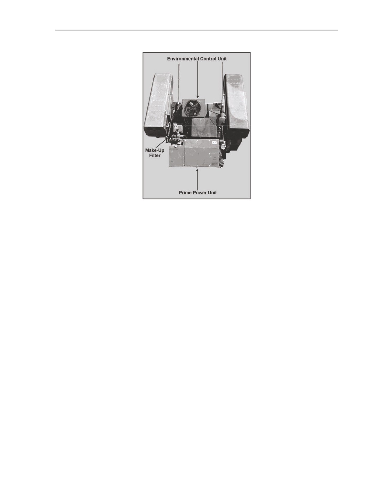
1-6. The turret gunner’s station incorporates an environmental control unit (ECU) that primarily consists
of a make-up filter and prime power unit to provide the gunner a controlled environment and protection
from chemical and biological hazards and unobstructed fields of fire. It can rotate through 360 degrees in
azimuth and from -10 degrees to +68 degrees in elevation. One SVML pod is mounted on each side of the
turret containing four Stinger missiles each. Missile reload time is 6 minutes or less. The turret gunner’s
station is shown in Figure 1-2.
1-2
FM 3-01.11
23 October 2007
Avenger
Figure 1-2. Gunner’s station
1-7. The turret gunner’s station is gyro-stabilized by a gyro attached to the turret floor which senses
changes in azimuth (direction) of the HMMWV and provides error signals to the electronics control
assembly to maintain continuous weapon pointing when in the stabilized mode.
1-8. The M3P .50-caliber machine gun is mounted on the right launch beam. It provides air defense
coverage inside the missile’s dead zone and provides for FU self-defense against hostile ground fire.
Linked ammunition consisting of 200 rounds is fed to the gun via a flexible feed chute.
REMOTE CONTROL UNIT
1-9. Using the RCU, the Avenger crew can operate the system remotely to a distance of 50 meters. The
hand control switches and indicators on the RCU are the same as those found on the gunner’s console, with
the exception that no adjustments to the FLIR can be made from the RCU. As the environment or weather
changes, it is critical the FLIR be kept properly adjusted at all times to ensure the RCU remains effective.
SENSOR PACKAGE
1-10. The Avenger A1 is equipped with a sensor package for target acquisition. The package includes the
FLIR, optical sight, IFF, and laser range finder (LRF). They are described below:
z
FLIR Receiver: The FLIR system provides enhanced acquisition capability in various
environments such as night, smoke, rain, backg1round clutter, or haze conditions. Once the
gunner has detected and acquired the target with FLIR, he may manually track the target using
the hand station. Or the gunner may select the automatic video tracker (AVT) by pressing and
releasing the right thumb switch on the hand station.
z
Optical Sight: The optical sight is used to conduct a heads-up engagement. It allows the gunner
to manually acquire targets through the canopy and to aim the missiles. The gunner will see the
same symbology that appears on the FLIR monitor, but without the auto-track reticule and the
narrow field of view fixed reticule.
z
IFF: The IFF located on the Avenger system consists of the AN/PPX/3A/B and is activated by
the gunner. This system allows the gunner to identify aircraft equipped with Mode 4 or Mode 3
programmed transponders as positive friend, possible friend, or unknown. In normal operation,
23 October 2007
FM 3-01.11
1-3
Chapter 1
the IFF system located on-board the FU sends a coded interrogation signal to the unidentified
aircraft. A reply is automatically generated and transmitted by the aircraft. Based on the IFF
response and visual identification, the gunner will either continue the engagement sequence or
opt to use search and scan procedures.
z
LRF: Range data from the LRF is processed by the analysis control element computer and is
displayed to the gunner on the control display terminal (CDT) in meters. The computer uses this
range data to determine fire permit and lead angle information for missile and gun use. A fire
permit symbol is not required to launch a missile; however, it is required to fire the machine gun
in the air or ground (auto) mode.
1-11. The Avenger A2 is equipped with the LRF, FLIR, FLIR monitor, the Avenger fire control computer
(AFCC), and the optical sight.
SLEW-TO-CUE SYSTEM
1-12. The Avenger slew-to-cue receives data from forward area air defense (FAAD) command and control
(C2) and intelligence activities. It processes and displays air track data to the driver and gunner, then
automatically slews the turret to the selected target.
SENSITIVITY TIME CONTROL MAJOR COMPONENTS
1-13. The AFCC provides for the sensitivity time control (STC) system integration and processing of all
incoming data from the crew chief air situation display. It passes this information to the gunner via the
targeting console. The STC system provides the gunner at the targeting console with information and
controls necessary to engage in air combat. It includes a system target tracking window with appropriate
symbology, system status menus, built-in-test (BIT) interface, and various other components.
1-14. The land navigation system (LNS) provides real-time headings and current positioning of the
Avenger STC FU and supports the STC’s ability to fire on-the-move while enhancing the necessity of
“first-to-fire.”
1-15. The cab interconnect panel was developed to simplify the cab wiring harness and provide the
required power circuitry protection for devices in the vehicle cab.
1-16. The slip ring contains other high current conductive rings alternately stacked with insulation rings to
allow the transmission of power and other electrical signals between the stationary and rotating segments
of the turret. The slip ring has been modified to include two additional connectors to support slew-to-cue.
1-17. The CDT displays essential operational information and allows direct interface with the RCU during
remote operations. The CDT operations are converted to LNS during normal operations.
1-18. The handheld terminal unit (HTU)/crew chief air situation display is a small computer terminal used
to receive, process, and display messages and data to accomplish operational function using the handheld
communications subsystem. The HTU is compatible with SINCGARS communications and is ported for
EPLRS support. However, the forward area computer terminal is replacing the HTU.
STINGER
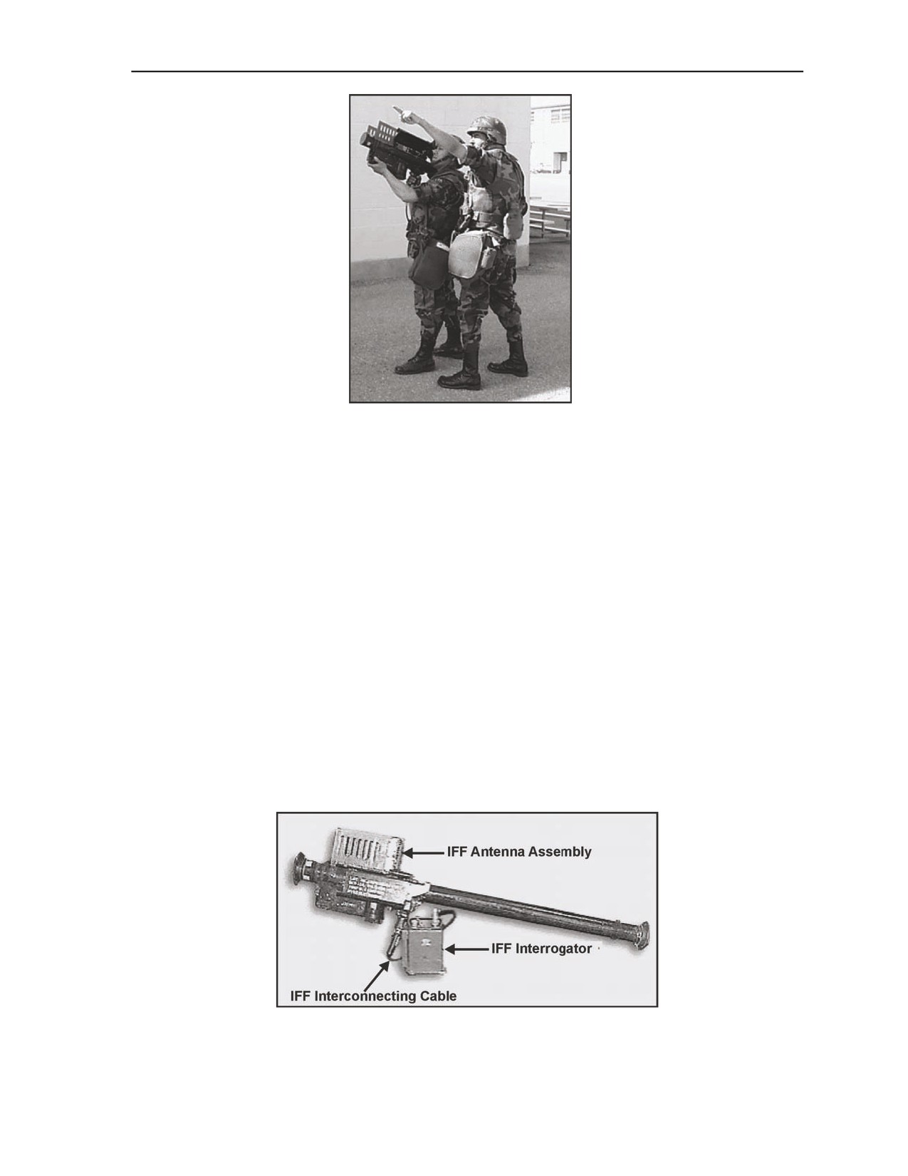
1-19. MANPADS shoulder-fired configuration is primarily used as a backup should the Avenger vehicle
or turret system malfunction (Figure 1-3). Stinger can be converted to the shoulder-fired configuration by
removing a missile-round from one of its two Avenger missile pods. A gripstock and BCU is then attached
to the launch tube and Stinger becomes a ready-weapon allowing it to be employed as a backup weapon
should the Avenger fire unit (FU) become degraded.
1-4
FM 3-01.11
23 October 2007
Avenger
Figure 1-3. Stinger MANPADS
1-20. The Stinger weapon system is fielded in two versions—the Stinger RMP version with its increased
improvements to the guidance section and increased capability to reject complex infrared countermeasures
(IRCMs), and the reprogrammable capability to meet the ever-changing threat without hardware redesign
or replacement. The RMP version is now being used exclusively by USAADASCH for student training
and qualification until all missiles are exhausted. However, all units are being fielded with Stinger
RMP/Block1 shown in Figure 1-4. Stinger RMP/Block1 version combines RMP and incorporates
refinements to the guidance system electronics. This upgrade provides the capability for the missile to
determine its “up” position during launch sequence. This allows the missile to bias its flight to counteract
gravitational forces and enhance missile performance in non-ideal scenarios, such as minimum target
elevation angles and low-target aspect angles in a clutter environment. The Stinger RMP/Block1 missile is
a heat-seeking guided missile that tracks to the target in the infrared/negative ultraviolet
(IR/NUV)
spectrums through proportional navigation. After firing, the gunner has no control over the missile and is
required only to observe the missile’s flight trajectory (path) to the target or opt to reengage another target.
Stinger incorporates an identification, friend or foe (IFF) interrogator system that assists the gunner and
team chief in identifying aircraft as “positive friend,” “possible friend,” or “unknown.” The final decision
to launch is always based on positive visual identification of the aircraft as “hostile.” Tactical weight of the
Stinger weapon-round with gripstock attached and BCU installed is 36.1 pounds. The weapon-round is
readily identified by four yellow,
1-inch squares located at each end of the launch tube and BCU
receptacle.
Figure 1-4. Stinger RMP/Block1
23 October 2007
FM 3-01.11
1-5
Chapter 1
1-21. Components that make up the Stinger weapon-round are: a missile housed in a fiberglass launch
tube; a permanently attached hinged open sight assembly located atop the fiberglass launch tube; a
gripstock with an IFF antenna, and a BCU installed. To assist the gunner in aircraft identification, the IFF
antenna is unfolded and the IFF interconnecting cable is connected beneath the firing trigger handgrip.
Interrogation function is accomplished by pressing the IFF interrogate switch located at the rear of the
gripstock. Stinger is a “fire-and-forget” system. This means that immediately after firing, the gunner
removes and discards the BCU from its receptacle, folds and stows the IFF antenna, unlatches the latch
mechanism located at the forward end of the gripstock, and removes the gripstock from the launch tube.
The launch tube is then discarded by various means of destruction such as crushing explosives or fire. The
gunner can now ready another missile-round for engagement or opt to seek cover after launch. The
gripstock is reused continually until failure. System self-containment capability is provided by an on-board
power and coolant supply source to power the missile during the prelaunch engagement phase. At trigger
closure, the on-board missile battery and argon coolant supply are enabled throughout the terminal flight
phase to the target. The RMP/Block1 improvement program extends the missile’s service life, while
providing improved accuracy and resistance to countermeasures, increased effectiveness against near-term
low-observable targets, and UA/UASs, CMs, and standoff helicopters in a clutter environment. The need
for superelevation eliminates a situation which would create a safety hazard when configured to launch
from a hovering helicopter.
MISSILE COMPONENTS
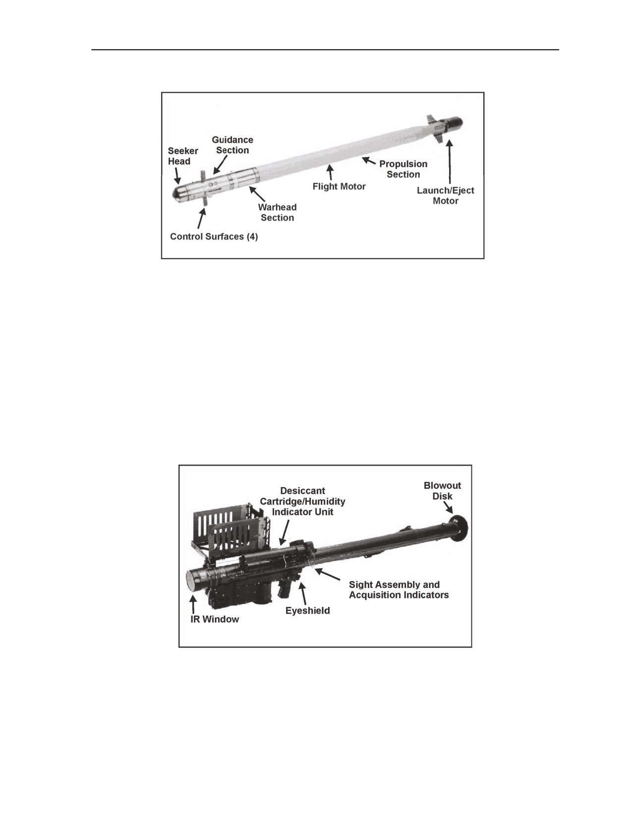
1-22. Figure 1-5 shows the Stinger missile and its components. The main components are as described
below:
z
Guidance section. The guidance section consists of the control surfaces assembly, on-board
argon gas for in-flight seeker head coolant, missile battery for in-flight power, and four spring-
loaded, deployable control surfaces for guidance. The guidance section processes target
IR/NUV and provides guidance commands to the missile during flight. Once the missile is
launched, it continues to track the IR/NUV source while the control assembly continues to
receive, process, and translate the guidance signals from the seeker. These signals are then
converted to guidance commands which provide for missile control surface movement.
z
Warhead section. The warhead section consists of a fuze assembly and a quantity of
explosives. Once the flight motor ignites, the fuze arms the warhead during its terminal flight
phase. The fuze will detonate the warhead in one of three ways—(1) low-impact switch, (2)
hard-target sensing, or (3) self-destruct if target intercept does not occur after approximately 15
to 19 seconds.
z
Propulsion section. The propulsion section is provided by the launch/eject motor and the duel-
thrust (boost and sustain phase) solid propellant flight motor. The launch/eject motor ejects the
missile to approximately 28 feet from the launch point, allowing the missile to coast a safe
distance prior to flight motor ignition. Once expended, the launch/eject motor separates from the
flight motor. A lanyard is attached between the launch/eject motor and the flight motor. As the
launch/eject motor separates, the lanyard pulls the shorting plug from the flight motor, initiating
ignition a safe distance from the gunner.
1-6
FM 3-01.11
23 October 2007
Avenger
Figure 1-5. Stinger missile components
LAUNCH TUBE ASSEMBLY
1-23. The Stinger launch tube assembly provides the means to transport, aim, and launch the missile. The
Stinger launch tube is the primary support assembly for all other components that convert it to a weapon-
round. Both ends of the launch tube are environmentally sealed with breakable disks. The forward end of
the sealed launch tube has an IR window which allows radiation to reach the heat-sensitive missile seeker.
At launch, the front and aft disks break outward as the launch eject motor ignites and missile movement
occurs. A cylindrical-shaped, replaceable desiccant cartridge, located atop the launch tube indicates the
presence of moisture, if any. The hinged open-sight assembly attached to the launch tube allows the gunner
to sight, determine range, determine when to superelevate the weapon, and to hear the audible tones
produced through the acquisition indicators—cheek-to-bone transducer (IR/NUV lock-on) and speaker
(IFF interrogator). The eyeshield attached to the sight frame protects the gunner’s left eye during missile
launch. Figure 1-6 shows the Stinger launch tube assembly.
Figure 1-6. Stinger launch tube assembly
23 October 2007
FM 3-01.11
1-7

Chapter 1
GRIPSTOCK RMP/BLOCK1
1-24. The RMP and RMP/Block1gripstock can be used with either version of the Stinger. They are shown
in Figures 1-7 and 1-8, respectively.
Figure 1-7. Stinger RMP gripstock
1-25. The Stinger gripstock is attached to the launch tube by means of a latch mechanism located forward
on the gripstock. Components that make up the gripstock are the IFF antenna assembly, IFF interrogate
switch, safety and actuator device, firing trigger, uncaging switch, IFF interrogator connector, and BCU
receptacle as shown in Figure 1-6. After missile launch, the BCU is removed immediately and the
gripstock is removed from the launch tube for reuse. The tactical gripstock is readily identified by a yellow,
1-inch square located on the BCU receptacle. The gripstock can be reused until failure. Stinger is capable
of interrogating and receiving coded replies. When not in use, the antenna assembly is folded and secured
on the right side of the gripstock. Gripstocks without the RMP module installed can be used, but the
missile will not have the enhanced performance capability. RMP-capable gripstocks contain the electronic
housing that accommodates the RMP module, allowing for reprogramming of missile software to enhance
performance in different threat environments.
Figure 1-8. Stinger RMP/Block1 gripstock
1-8
FM 3-01.11
23 October 2007

Avenger
BATTERY COOLANT UNIT
1-26. The BCU is a thermal battery that generates extreme heat once activated. This thermal battery
enables power to the missile electrical circuitry and argon coolant to the seeker during prelaunch
operations. Due to this extreme heat, the BCU must be removed from the gripstock BCU receptacle
immediately or within 3 minutes after missile launch to prevent damage to the gripstock. Due to excessive
heat generated by the BCU, removing and handling the BCU must be done with caution to prevent burns to
the hands. The BCU also houses pressurized argon gas to cool the IR/NUV detector prior to missile launch.
The needle located atop the BCU through which argon gas travels to the seeker for cooling should be
checked for damage and the rubber grommet should not be pushed down, exposing open end of needle. In
Figure 1-9, the rubber grommet has been pushed down, exposing the open end of the needle. The contact
rings (atop the BCU) are checked for corrosion and its housing checked for cracks. The tactical BCU is
readily identified by one, 1-inch yellow square located on the body of the BCU.
Figure 1-9. Stinger BCU top view
1-27. Located on the base of each BCU is a heat-sensitive indicator (HSI) and the burst disk diaphragm.
The HSI should be pink or white (serviceable) as shown in Figure 1-10 and not dark grey (unserviceable).
The burst disk diaphragm should be silver. Should any one of the aforementioned items be found defective,
the BCU should be returned to the ammunition supply point.
Figure 1-10. Stinger BCU base
IFF ANTENNA AND INTERROGATOR SUBSYSTEM
1-28. The Stinger IFF interrogator subsystem is equipped with the AN/PPX-3 A or B (hereinafter referred
to as the AN/PPX-3) IFF interrogator belt pack, IFF interconnecting cable, IFF antenna assembly, and a
BCU to aid the gunner in identification of aircraft. See Figure 1-11. The basic visual differences between
the two versions, A and B, is the addition of an electronic day indicator activating switch and a readout
indicator located atop the interrogator on the B version. The interrogator is identified by a series of 1-inch
yellow squares located horizontally around the mid-section of the unit. The IFF system classifies aircraft as
either Mode 4 positive friend (half-second beep, pause, half-second beep) and is considered a “true friend”
23 October 2007
FM 3-01.11
1-9

Chapter 1
reply; or, if not received, automatically switches to Mode 3 (a single, one and one-half-second beep) and is
considered only a “possible friend” reply. It does not identify aircraft as hostile. Should the aircraft’s
transponder return an incorrect reply or no reply, the audible response will be “unknown” (a string of
beeps). If no tone is heard, the IFF system is either nonoperational or the interconnecting cable is not
secured correctly to the gripstock.
Figure 1-11. Stinger IFF antenna and interrogator subsystem
1-29. When the aircraft is placed in the range ring, the gunner initiates the IFF sequencing by pressing the
IFF INTERROGATE switch on the gripstock. Once the gunner issues a challenge, the AN/PPX-3 transmits
a coded signal to the aircraft. The aircraft’s transponder then processes the signal and returns a coded reply.
The reply is received by the Stinger IFF antenna and is routed through the interconnecting cable to the
AN/PPX-3 for decoding. The AN/PPX-3 then converts the reply into an audible tone which is then
rerouted via the cable to the gunner as a positive or possible friend tone through the speaker.
IFF INTERROGATOR SYSTEM SUPPORT EQUIPMENT
1-30. Figure 1-12 shows the support equipment for the Stinger IFF interrogator system. The support
equipment consists of the following:
z
IFF interconnecting cable.
z
AN/PPX-3A or B IFF interrogator.
z
An AN/GSX-1 or AN/GSX-1A IFF programmer/battery charger.
z
KOI-18/transmission security (TSEC) tape reader.
z
KIR-1C/TSEC computer/power supply model ZAC A/1.
z
W1 program cable, W2 power cable, W3 computer cable, and a W4 tape reader cable.
z
IFF interconnecting cable.
1-10
FM 3-01.11
23 October 2007

Avenger
Figure 1-12. Stinger IFF AN/GSX-1 interrogator system support equipment
1-31. The KIR-1C/TSEC computer can only be loaded with 2 days of codes at one time from the KOI-
18/TSEC tape reader and are classified as CONFIDENTIAL and must be safeguarded as outlined in TB
380-41. The evaluator module located within the interrogator is also classified CONFIDENTIAL, and
proper security measures must be taken. The AN/GSX-1 programmer/battery charger is being modified to
the 1A configuration to accommodate the AKAT 3662 “live-code” tape, the AKZT 3662 training tape for
the tape reader, and the AN/CYZ-10 automated network control device (ANCD) shown in Figure 1-13.
Figure 1-13. AN/GSX-1A, KIR-1C/TSEC, and KOI-18/TSEC
23 October 2007
FM 3-01.11
1-11

Chapter 1
WEAPON-ROUND METAL SHIPPING AND STORAGE CONTAINER
1-32. The Stinger weapon-round metal shipping and storage container provides environmental protection
for one complete weapon-round; three BCUs, one set of earplugs, and an attached gripstock. The weapon-
round container (WRC) identification markings are yellow with two, 2 ½-inch squares located at each
corner (top and bottom) of the container. The container is environmentally secured by four latches. A
lifting and carrying handle at each end allows for the minimum two-man carry safety requirement. A push-
and-release pressure relief valve is located on the lower latch side, forward end of the container to relieve
internal container pressure prior to opening. A humidity indicator viewing port is located at the lower right,
forward end of the WRC and indicates the percentage of moisture, if any, within the container. See Figure
1-14.
Figure 1-14. Stinger weapon-round metal shipping and storage container
MISSILE-ROUND WOODEN SHIPPING AND STORAGE CONTAINER
1-33. The Stinger missile-round is shipped in a distinctive wooden missile-round container (MRC) shown
in Figure 1-15. It can hold a missile-round, three BCUs, and one set of earplugs housed in a sealed barrier
bag. The humidity indicator viewing port functions in the same manner as on the WRC. A gripstock with
IFF antenna is not included.
Figure 1-15. Stinger missile-round wooden shipping and storage container
EMPLOYMENT CONSIDERATIONS
1-34. The areas listed below must be considered when employing the Stinger:
z
Assigned sectors of fire established.
z
Primary and alternate firing positions established.
z
Missile backblast requires 45 meters (150 ft) of clearance behind the weapon.
1-12
FM 3-01.11
23 October 2007
Avenger
z
Personnel within 125 meters (400 feet) must wear hearing protection.
z
No firing with the launch tube elevated more than 65 degrees or less than 10 degrees, or with the
aft end of the launch tube closer than approximately 30 inches from the ground, to minimize the
possibility of injury from flying debris.
STATIONARY POINT DEFENSE
1-35. Stinger’s ability to engage approaching aircraft makes it valuable for stationary point defenses. Its
effectiveness is significantly enhanced when other ADA systems are allocated to the same defense. Teams
should normally be positioned so that the engagement capability of one team overlaps that of an adjacent
team. Positioning teams from 2 to 3 kilometers apart will provide this capability. In cases where more than
one weapon system is employed in the same defense, overlapping fires should be achieved between
weapon systems. When the tactical situation permits, teams must be positioned far enough out from the
defended asset(s) to allow for early engagement (meaning the engagement of aircraft prior to ordnance
release).
MOBILE POINT DEFENSE
1-36. Stinger provides the ADA commander with an excellent capability to protect mobile assets to
include moving maneuver units. MANPADS teams will often provide air defense for units moving in
convoy or march column along roads behind the line of contact. Stinger defense of such convoys may be
conducted by either pre-positioning teams along the route of march at key points, such as choke points and
bridges, or integrating the teams into the march column. When integrated into the convoy, the positioning
of the MANPADS teams will depend on convoy length and available MANPADS weapons.
1-37. Placing the team away from the defended asset is desired whenever possible for engagement and
destruction of the target prior to its ordnance release line, providing gunners sufficient time to ready their
weapons. When not alerted, teams will have their MANPADS configured weapons nearby even as they
perform their own security and maintenance duties. System effectiveness largely depends upon gunner
reaction time. The teams need to know the weapon control status in effect at all times to increase their
effectiveness. Moreover, teams should be well trained on types of aircraft expected to operate within the
theater of operation and those expected tactics these aircraft would use.
23 October 2007
FM 3-01.11
1-13
This page intentionally left blank.
Chapter 2
Patriot
This chapter describes the Patriot air defense weapon system and the roles Patriot
plays in supporting the various types of AMD operations. Patriot provides critical
AMD support to a variety of mission scenarios. It is critical in all situations that C2,
coordination, identification of friendly and enemy assets, and protection of the forces
are maintained. For this to occur, Patriot must maintain critical links with U.S. and
allied members of the Joint Theater Forces through its communications assets.
MISSION
2-1. The mission of Patriot is to protect forces and selected geopolitical assets from aerial attack, missile
attack, and surveillance. Patriot provides protection against theater missiles (TMs) and air threats to critical
assets in the corps and theater areas. TMs constitute the primary threat to be countered by Army ADA
forces. Patriot can be tailored to the tactical situation in defending against air and missile attack.
ROLE
2-2. The role of the Patriot system is to accomplish the air defense mission within the low-altitude to
high-altitude boundaries because of its firepower, range, and altitude capabilities. Patriot is the lower-level
tier of a two-tier TM terminal defense system.
2-3. Patriot units are employed to protect forces and critical assets in all types of operations. Patriot units
may be deployed individually or as part of an ADA task force (ADATF) to protect entering forces,
airfields, seaports, transportation centers, population centers, C2, communications system, and intelligence
activities, and geopolitical assets. The ADATF may include THAAD, SHORAD weapon systems, and
other joint and multinational units.
THREAT DURING LODGMENT ENTRY OPERATIONS
2-4. Patriot helps to secure the lodgment in entry operations. As the theater develops and entering forces
expand into corps areas, Patriot units support the shaping and decisive operations. Some Patriot units move
with maneuver forces to provide protection for these forces and critical assets. Other Patriot units remain at
theater of operations and continue to provide air and missile defense of critical assets.
2-5. Some Patriot units may remain in theater as a conflict is resolved. These units prevent residual
enemy forces from successfully attacking geopolitical assets or friendly forces that are being redeployed.
2-6. Patriot may deploy during operational environment operations to contain localized conflicts, thus
obviating the need for a major military response. In these conflicts, Patriot units can be employed to protect
forces, civilian populations, and selected military and civilian assets from air, missile, and surveillance
threats.
Contents
2-7. Patriot units may also be used to promote
stability within a country or region. In some
Mission
2-1
countries, terrorists or rogue elements may threaten
Role
2-1
to disrupt normal civil and political activities using
Threat During Lodgment Entry
Operations
2-1
Physical Description of Major Items
2-2
23 October 2007
FM 3-01.11
2-1

Chapter 2
air and missile threats. Patriot units may be deployed to protect civilians and geopolitical assets, thereby
discouraging enemy factions and promoting stability.
PHYSICAL DESCRIPTION OF MAJOR ITEMS
2-8. Patriot is a guided missile (GM) system designed to defeat the AMD threat, which may include
tactical ballistic missiles (TBMs), air-to-surface missiles (ASMs), CMs, FW and RW aircraft, and UASs.
The system normally fights as a battalion, which usually consists of five batteries or fire units operating
under the control of a fire direction center. However, there are some battalions that are currently structured
to have six batteries due to theater and type of mission.
2-9. Physical descriptions of the major end items are provided below. More detailed descriptions of these
items, their components, and subsystems can be found in the system manuals listed in the References
section of this manual.
ELECTRIC POWER PLANT III
2-10. The electric power plant III (EPP III) is the prime power source for the engagement control station
(ECS) and radar set (RS) and consists of two 150-kw generators mounted on a 10-ton heavy expanded
mobility tactical truck (HEMTT). See Figure 2-1. The electric power unit (EPU) is the prime power source
for the information and coordination central (ICC) and communications relay group (CRG). Each ICC and
CRG has an EPU, which consists of a 30-kw generator mounted on a PU 789 M trailer as shown in Figure
2-4 on page 2-4.
Figure 2-1. Electric power plant III
INFORMATION AND COORDINATION CENTRAL
2-11. The ICC consists of a lightweight, weather-tight, shelter mounted on a 5-ton cargo truck (AN/MSQ-
104) as shown in Figure 2-2. The shelter provides shielding from radio frequency interference (RFI) and
electromagnetic pulse (EMP) radiation. It is equipped with two externally mounted air conditioners that
cool, heat, and ventilate the interior. An externally mounted gas particulate filter unit (GPFU) is used in
CBRN situations to provide clean air for crew members.
2-12. The ICC contains two consoles that are manned by the tactical director (TD) and tactical director
assistant
(TDA) to execute engagement operations. A communications work station is manned by a
network switch operator. At least three crews of three personnel each must be available for continuous 24-
2-2
FM 3-01.11
23 October 2007

Patriot
hour operations. Between the two consoles is an ICC status panel that displays the status of all battalion
fire units.
Figure 2-2. Information and coordination central
TACTICAL COMMAND SYSTEM
2-13. The tactical command system (TCS), a 5-ton, truck-mounted, expandable shelter shown in Figure 2-
3, is a highly mobile all-weather facility emplaced near the battalion ICC. It exchanges data with the ICC
as well as provides voice communications. It provides the Patriot air defense battalion commander with
state-of-the art equipment to implement and coordinate tactical planning and management activities. It is a
facility which accommodates the commander and staff personnel with automated equipment to support
force operation tasks that develop defense design planning. At least three crews with three personnel each
must be available for continuous 24-hour operations.
2-14. The TCS has active software programs that help planners translate airspace control measures into
Patriot initialization data for the battalion. The TCS consists of an air and missile defense workstation
(AMDWS), a tactical planner workstation (TPW), common data link interface (CDLI), joint tactical
terminal (JTT), and tactical satellite (TACSAT). It can display real time data based on operator selections.
The TCS capabilities include, but are not limited to—
z
Map display and control.
z
Tactical overlays.
z
Air situation.
z
Deployment planning.
z
Battle situation monitoring.
z
Initialization data sent to the ICC.
23 October 2007
FM 3-01.11
2-3

Chapter 2
Figure 2-3. Tactical command system with 15-kw generator
COMMUNICATIONS RELAY GROUP
2-15. The CRG consists of a weather-tight, CBRN-proof, shelter attached to a 5-ton cargo truck with a
trailer-mounted EPU as shown in Figure 2-4. It is similar in appearance to the ECS. It provides a
multirouted secure, two-way data relay capability, as well as voice communications between the ICC, its
assigned fire units, and between adjacent units. The CRG can also operate as launch control station (LCS).
This capability is critical for remote launch phase-3 operations. The CRG also provides the capability for
both data and voice exit and entry communication points with elements that are external to Patriot. A 24-
hour continuous operation is needed to meet mission requirements.
Figure 2-4. Communications relay group with EPU
ENGAGEMENT CONTROL STATION
2-16. The ECS consists of a lightweight, weather-tight, shelter mounted on a 5-ton cargo truck (AN/MSQ-
104) as shown in Figure 2-5. The shelter provides shielding from RFI and EMP, and, like the ICC, is
equipped with two externally-mounted air conditioners and a GPFU. The left side, as seen from the
doorway, includes three ultrahigh frequency (UHF) radio relay terminals, and a voice communications
station. The right side includes the very high frequency (VHF) data link terminal (DLT), radar weapons
control interface unit (RWCIU), weapons control computer (WCC), an AN/VRC-92A SINCGARS radio,
2-4
FM 3-01.11
23 October 2007

Patriot
tactical storage device, and embedded data recorder. The ECS crew consists of a tactical control assistant
(TCA), tactical control officer (TCO), and communications personnel. Three crews of three personnel each
are responsible for running 24-hour continuous operations.
Figure 2-5. Engagement control station
BATTERY COMMAND POST
2-17. Technology is now being integrated for the battery command post (BCP), Figure 2-6. The new
Patriot BCP provides sheltered communications, computer and display facilities, as well as working space
for the battery commander and staff. BCP equipment includes a HMMWV with a deployable rapid
assembly shelter modular tent, which attaches to the back side of the vehicle.
2-18. Within the vehicle are an AMDWS station and a common hardware and software computer with an
attached 8-mm tape drive and printer. The BCP runs off of a 10-kw generator. BCPs have dedicated
elements to implement emergency survivability measures in case of chemical or ground attacks.
2-19. The BCP is operated by a crew of two AD C2 communications system and intelligence tactical
operations center (TOC) operators/maintainers. At least three crews must be available for continuous, 24-
hour operations. The crew members are responsible for operating, maintaining, march ordering, and
emplacing the BCP. Personnel required to support BCP operations must be capable of operating the
AMDWS. Some of the BCP functions include—
z
Tactical digital information link
(TADIL)-J messages received and displayed on the BCP
workstation.
z
Situation awareness and early warning.
z
Automated defense design and planning.
z
AMDWS functionality/routing staff support.
z
Integrated scenario development.
z
AMDWS/tactical air planner capabilities to support defense planning and air battles.
z
Intelligence received and processed.
23 October 2007
FM 3-01.11
2-5

Chapter 2
Figure 2-6. Battery command post
RADAR SET
2-20. The RS (Figure 2-7) consists of a multifunction, phased array radar mounted on an M-860
semitrailer towed by an M983, HEMTT. It is monitored and controlled by the ECS via the RWCIU. The
RS performs very low- to very high-altitude surveillance, target detection, target classification, target
identification, target track, missile track, missile guidance, and electronic counter-countermeasures
(ECCM) functions.
2-21. The radar antenna is positioned at the forward end of the shelter and is erected to a fixed 67.5-degree
angle relative to the horizontal plane during emplacement. Integral leveling equipment on the M-860
semitrailer permits emplacement on slopes of up to 10 degrees.
Figure 2-7. Radar set
2-6
FM 3-01.11
23 October 2007

Patriot
PAC-3 AN/MPQ-65 RADAR
2-22. The Patriot Advanced Capability-3 (PAC-3) AN/MPQ-65 radar, with new enhancements, provides
significant improvements in expanded search, threat detection, and identification and engagement
capability. In addition, the radar search sector volume has been expanded and a search-tailoring feature has
been incorporated. PAC-3 radar enhancements provide for additional search sectors that improve search
and track functions against TBM threats. The addition of the high-altitude cruise missile search sector
enhances the system’s ability to detect and counter air-launched cruise missiles.
PAC-3 LAUNCHER
2-23. The launching station (LS) is mounted on an M-860 semitrailer towed by an M983 HEMTT (Figure
2-8). Leveling equipment permits LS emplacement on slopes of up to 10 degrees. The LS is trainable in
azimuth ±110 degrees and elevates to a fixed, elevated, launch position. The LS has to be precisely
emplaced and aligned prior to launch. Proper emplacement and alignment are critical for engagement of
any threat.
2-24. The current Patriot launcher has been modified to accommodate the new PAC-3 missile and serves
as an interchangeable launcher platform. The upgraded launcher is referred to as a PAC-3 launcher and is
capable of accommodating the PAC-3 missile or the current inventory of Patriot missiles.
2-25. Each PAC-3 launcher will include the enhanced launcher electronics system (ELES), a junction box
(J-box) containing a launching station diagnostic unit (LSDU), and new interface and umbilical cables for
the PAC-3 missile. The ELES performs the electrical interface functions between the PAC-3 launcher and
the PAC-3 missiles to the ECS through the fiber-optics cable or SINCGARS VHF radio.
2-26. The ELES replaces the launcher electronics module (LEM) and occupies the same location on the
launcher. The power distribution unit internal to the LEM was replaced with a peripheral control unit
(internal to the ELES) for control of additional power supplies required by the PAC-3 missile functions.
The J-box replaces the launcher/missile round distributor on PAC-3 launchers.
2-27. During operations, the ELES may be connected to 16 PAC-3 missiles or four PAC-2 missiles. The
ELES is comprised of the launch control unit, motor control unit, power control unit, connector interface
panel, and J-box. The J-box interfaces the ELES and missile canisters, either PAC-2 or PAC-3 missiles.
There is no mixing of PAC-3 missiles or PAC-2 missiles on the same launcher.
2-28. The generator for the LS is located on the yoke assembly of the trailer and includes a built-in 56.8-
liter (15-gallon) fuel tank. It has side-mounted work platforms. The unit is diesel engine-driven, 15-kw,
four-wire, 400-hertz, with 120/208-volt power.
Figure 2-8. Patriot PAC-2 or PAC-3 LS (emplaced)
23 October 2007
FM 3-01.11
2-7

Chapter 2
ANTENNA MAST GROUP
2-29. The antenna mast group (AMG), as illustrated in Figure 2-9, is a mobile antenna mast system used to
carry the amplifiers and antennas associated with the UHF communications equipment located in the ECS,
ICC, and CRG. Four antennas are mounted in two pairs, are remotely controlled in azimuth, and can be
elevated to heights up to 100 feet and 11 inches, above ground level.
2-30. Emplacement consists of stabilizing the AMG, setting the antenna feed and the erection of the
antennas by the use of self-contained hydraulic and pneumatic systems and then adjusting the antenna
azimuth. The emplacement slope for the AMG should not be more than 10 degrees for crossroll and ½
degree for roll. Connecting cables to the collocated shelter are carried on the AMG, which also includes
radio frequency (RF) cables, control cables, and a prime power cable.
Figure 2-9. Antenna mast group
PAC-3 MISSILE CHARACTERISTICS
2-31. The PAC-3 missile is considerably smaller than the other Patriot missiles, as viewed in Figure 2-10,
allowing 16 to be loaded onto the launching station versus four of the others. Because the different
versions have different capabilities and limitations, there are strict guidelines regarding their selection and
use against different threats. (For more detailed information, refer to FM 3-01.85.)
2-8
FM 3-01.11
23 October 2007

Patriot
Figure 2-10. Patriot missiles
2-32. The current Patriot missile inventory includes seven different missile types. These missiles come in a
missile canister, packaged one missile per canister and shipped as a certified round. They are referred to
as—
z
Standard (MIM-104/MIM-104A). This was the first missile fielded with Patriot and contained
an analog fuze. This fuze was replaced by a digital version with the fielding of the MIM-104A.
Both missiles provide excellent performance against air-breathing threats (ABTs) and adequate
performance against certain TBMs. The warhead fragment size limits performance against
TBMs to a mission kill.
z
Standoff jammer counter (SOJC). The SOJC missile (MIM-104B) is used to counter the long-
range electronic countermeasures (ECM) threat. The guidance and navigation hardware was
modified to allow the missile to fly a lofted trajectory to the jamming source and seek out the
strongest emitter during the terminal phase. To achieve the lofted trajectory needed to maintain
missile maneuverability at long range, missile acquisition is delayed for the SOJC mission. The
SOJC missile retains the same performance against ABTs and TBMs as the standard missile.
z
ATM (antitactical missile). The ATM missile (MIM-104C, PAC-2) is used to counter the
advanced TBM threat. The missile has a new warhead and dual-mode fuze. The new dual-mode
fuze allows the ATM missile to retain ABT performance and optimize TBM fuzing. The system
software based on the specific mission selected for the missile sets the fuze mode.
z
ATM1. The ATM1 missile (MIM-104D, guidance-enhanced missile [GEM]) provides improved
capability over the ATM missile against TBMs and advanced ABTs. The ATM1 improves
system effectiveness and lethality against high-speed TBMs and incorporates a footprint with
and increased probability of kill. The ATM1 also has an increased lethality against advanced
low radar cross-section (RCS) ABTs. There is an improved sensitivity in the track via missile
(TVM) seeker, and an improved fuze reaction time.
z
ATM1T. The ATM1T missile (MIM-104E, GEM+) provides a greater improvement over the
ATM1 missile against high-speed TBMs, against the CM threat, and against low RCS, low-
altitude ABT threats. The ATM1T has an improved low noise frequency generator that increases
the sensitivity of the TVM seeker. This low noise frequency generator modification required
23 October 2007
FM 3-01.11
2-9
Chapter 2
improvements to the fuze processor to provide an even greater sensitivity and earlier detection
of targets.
z
ATM1C. PDB-6 has added the capability of the new ATM1C missile (MIM-104F, GEM
variant) along with the already fielded missiles. The new missile type is selectable for all target
types and provides a greater improvement and greater lethality against CMs and against low
RCS, and low-altitude ABT threats.
z
ATM2. The ATM2 missile (PAC-3) provides the best performance against the high-speed TBM
threat. The ATM2 missile incorporates into the missile its own on-board high resolution active
seeker antenna, which communicates directly with the fire solution computer in the ECS through
the RS. This has the advantage of the missile not using any assigned TVM tracking slots during
the terminal phase of the engagement. The ATM2 missile is a hit-to-kill missile and has no
warhead, but does employ a lethality enhancer that increases the odds of a first-shot kill. To
provide it with the capability of hit-to-kill, it incorporates an aerodynamic/thrust-maneuvering
system. The ATM2 missile is vastly different from the other missiles in that it is longer and not
as wide, and is shipped with four missiles per canister.
2-33. There are no visible differences between the standard, SOJC, ATM, ATM1, ATM1T, and ATM1C.
2-34. The Patriot missile comes as a certified round, meaning that the missile requires no checkout prior to
launch. The missile is shipped in a canister, which also serves as a launching tube.
BATTALION MAINTENANCE EQUIPMENT/BATTERY MAINTENANCE GROUP
2-35. Patriot support equipment consists of standard Army vehicles that have been modified and equipped
for use with the Patriot system. They function as the maintenance and supply centers required for Patriot
tactical equipment at the battery and battalion headquarters levels. Patriot support equipment is shown in
Figure 2-11. Repair parts, maintainer tools, test and handling equipment, publications, and maintenance
and supply records are stored in the vehicles. These items are described below:
z
The maintenance center (MC) is a semitrailer-mounted shop van that contains the tools, and test
and handling equipment necessary to maintain the Patriot system. It is used at battery and
battalion levels. The headquarters and headquarters battery (HHB) MC is configured to function
as a small repair parts transporter (SRPT). The PU-732M, 15-kw, 400-hz, trailer-mounted,
diesel generator set provides the power.
z
The guided missile transporter (GMT) is a modified HEMTT M985 with a heavy-duty materiel-
handling crane attached at the rear of the vehicle. It can be used for the delivery, recovery, and
loading of guided missiles. It is on the HHB TOE. Location of the GMT (whether it remains at
the battery or is retained at the battalion S-4 during combat or other operations) is determined by
how missiles will be resupplied to the battalion.
z
The large repair parts transporter (LRPT) is a HEMTT M977 cargo truck with a light duty
material-handling crane. It is used to store and transport large, heavy repair parts.
z
The SRPT provides a means to transport small repair parts and assemblies. It is also used as a
maintenance van when needed.
2-10
FM 3-01.11
23 October 2007
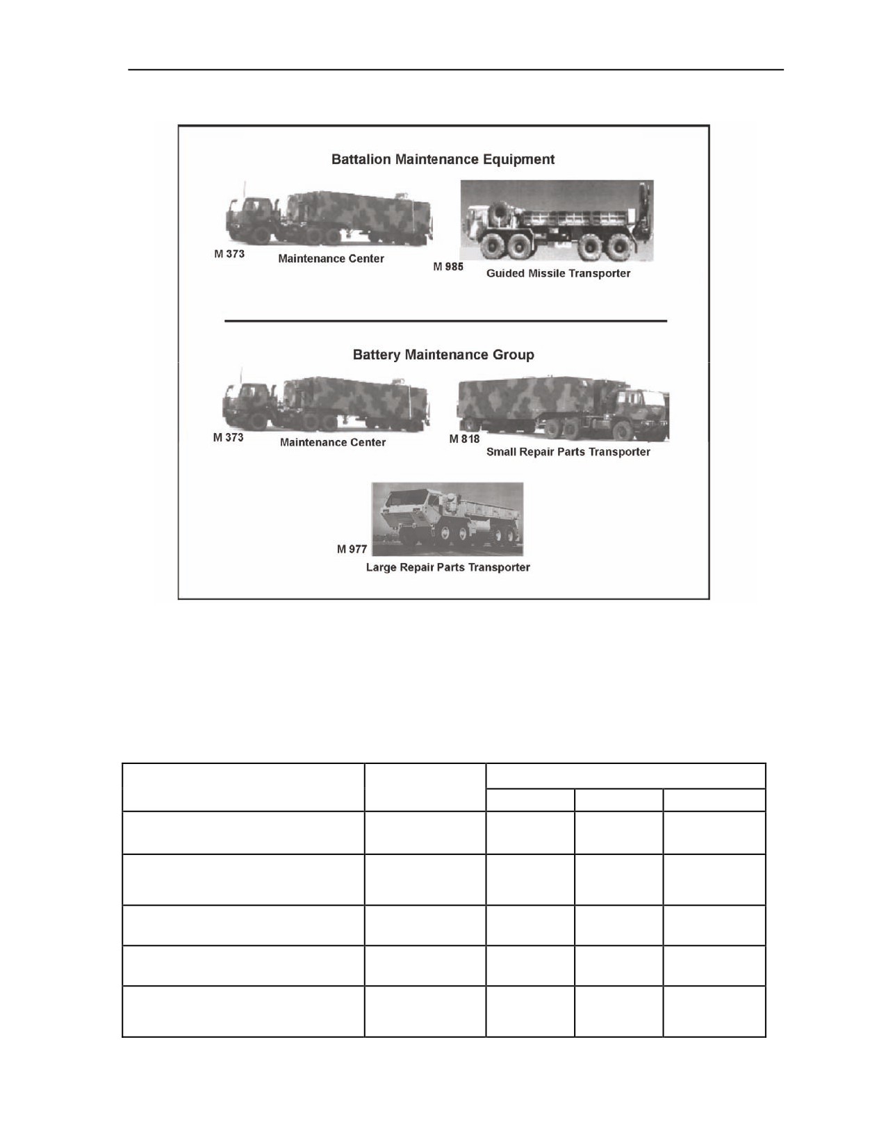
Patriot
Figure 2-11. Patriot support equipment
TACTICAL EQUIPMENT WEIGHTS AND DIMENSIONS
2-36. Table 2-1 provides approximate weights and dimensions of tactical equipment in both customary and
metric systems. This table also includes the weight of water and fuel.
Table 2-1. Patriot tactical equipment weights and dimensions
Maximum Overall Dimensions
Maximum
Equipment
Weight
Height
Width
Length
RS with M983 prime mover (AN/MPQ-
78,030 lb
11.83 ft
9.52 ft
55.77 ft
65)
35,485 kg
3.61 m
2.90 m
17.00 m
ECS, mounted, (AN/MSQ-104) with
37,780 lb
11.92 ft
8.95 ft
32.10 ft
M927, 5-ton tractor truck without
17,137 kg
3.63 m
2.73 m
9.78 m
winch
EPP III mounted on M977 tractor with
59,910 lb
11.25 ft
8.5 ft
33.4 ft
winch
27,174 kg
3.43 m
2.59 m
10.18 m
AMG, OE-MRC, with M942, 5-ton
37,170 lb
1.75 ft
8.26 ft
35.13 ft
tractor with winch
16,860 kg
3.58 m
2.52 m
10.71 m
LS, GM with 15-kw generator, with
67,010 lb
11.50 ft
9.42 ft
55.96 ft
M983 tractor and trailer, no
30,395 kg
3.50 m
2.87 m
17.06 m
missiles
23 October 2007
FM 3-01.11
2-11

Chapter 2
Table 2-1. Patriot tactical equipment weights and dimensions (continued)
Maximum Overall Dimensions
Maximum
Equipment
Weight
Height
Width
Length
LS, GM, with 15-kw generator with
82,010 lb
13.08 ft
9.42 ft
55.96 ft
M983 tractor and trailer with four
37,199 kg
3.99 m
2.87 m
17.06 m
GMs (PAC-2)
Four GMs (PAC-2) with canisters, no
15,000 lb
6.50 ft
7.04 ft
20.0 ft
truck, no trailer
6,804 kg
1.98 m
2.15 m
6.10 m
PAC-3 launcher trailer set, without
35,000 lb
11.50 ft
9.42 ft
33.66 ft
prime mover, with 15-kw
15,876 kg
3.50 m
2.87 m
10.26 m
generator, no missiles
Four GMs (PAC-3) with canister, 16
18,552 lb
6.50 ft
7.04 ft
20.0 ft
missiles total, no truck, no trailer
8,415 kg
1.98 m
2.15 m
6.10 m
PAC-3 LS, without prime mover, with
15-kw generator, with four GMs
53,552 lb
13.08 ft
9.42 ft
33.66 ft
(PAC-3) with canister, 16 missiles
24,291 kg
3.99 m
2.87 m
10.26 m
total
EPU II PU 804, trailer-mounted, no
5,920 lb
7.00 ft
7.92 ft
13.75 ft
tractor, full with fuel
2,685 kg
2.13 m
2.41 m
4.19 m
40,680 lb
11.42 ft
8.17 ft
46.07 ft
MC with M932 tractor
18,452 kg
3.48 m
2.49 m
14.04 m
39,390 lb
11.42 ft
8.17 ft
46.07 ft
SRPT with 5-ton M932 tractor
17,867 kg
3.48 m
2.49 m
14.04 m
LRPT with light duty materiel handling
equipment crane, with M977
40,241 lb
11.92 ft
8.44 ft
33.42 ft
tractor with winch assembly
18,253 kg
3.63 m
2.57 m
10.19 m
(prescribed load list parts not
included)
GMT truck with heavy duty crane, no
missiles, M985E1 tractor and
41,090 lb
6.08 ft
8.44 ft
35.73 ft
trailer with winch
18,638 kg
1.85 m
2.57 m
10.89 m
ICC, AN/MSQ-16, with M928 5-ton,
37,000 lb
11.99 ft
8.54 ft
32.08 ft
tractor without winch assembly.
16,783 kg
3.66 m
2.60 m
9.78 m
CRG, AN/MRC-137, with M927 5-ton,
34,690 lb
11.99 ft
8.54 ft
32.08 ft
tractor without winch assembly
15,735 kg
3.66 m
2.60 m
9.78 m
TSC, AN/MSQ 129, with M934A1
29,280 lb
11.86 ft
8.17 ft
30.22 ft
tractor
13,309 kg
3.61 m
2.49 m
9.21 m
32,880 lb
9.25 ft
8.46 ft
29.29 ft
HEMTT, 10-ton, M983
14,914 kg
2.82 m
2.58 m
8.93 m
2-12
FM 3-01.11
23 October 2007
Patriot
Table 2-1. Patriot tactical equipment weights and dimensions (continued)
Maximum Overall Dimensions
Maximum
Equipment
Weight
Height
Width
Length
HEMTT, 10-ton, M983, fuel-empty-
38,165 lb
9.25 ft
8.46 ft
33.4 ft
2,500 gal
17,311 kg
2.82 m
2.58 m
10.18 m
50,900 lb
9.25 ft
8.46 ft
32.7 ft
HEMTT, 10-ton, M984A1 wrecker
23,088 kg
2.82 m
2.58 m
9.97 m
EPP III vehicle-mounted on M977
52,910 lb
11.25 ft
8.5 ft
33.40 ft
tractor with winch
24,000 kg
3.43 m
2.59 m
10.18 m
6.7 lb
JP-8 fuel (1 gal)
3.04 kg
8.0 lb
water (1 gal)
3.63 kg
23 October 2007
FM 3-01.11
2-13
This page intentionally left blank.
Chapter 3
Terminal High-Altitude Area Defense
This chapter describes the THAAD system, its mission and components. The
THAAD system is a unique ballistic missile defense (BMD) system with both
endoatmospheric and exoatmospheric intercept capability with high probability of
kill.
MISSION
3-1. The mission of the THAAD battery is to protect the homeland, deployed military forces, friends, and
allies from short-range ballistic missiles (SRBMs) and medium-range ballistic missiles (MRBMs). In the
future, THAAD may develop a capability against intermediate-range ballistic missiles (IRBMs). THAAD
is a ground-based, deployable terminal missile defense system being fielded. As an element of the ballistic
missile defense system (BMDS) terminal defense segment, THAAD will provide the opportunity to
conduct endoatmospheric and exoatmospheric engagements against BMs that were not destroyed earlier in
boost or midcourse phases of flight by other BMDS elements.
3-2. In the BMDS, THAAD is part of a terminal phase segment and is the upper tier defense of a
multilayer defense system. While a single level, or tier, defense can provide a robust degree of protection
for defended assets, a two-tier defense is required to provide a near-leak-proof defense at greater altitudes
and ranges for defense of most critical assets. THAAD provides defense against threats directed against
critical military assets and geopolitical assets. THAAD engages at high altitudes and long ranges to
minimize collateral damage caused by CBRN warheads and debris.
GENERAL TRAJECTORY PHASES
3-3. The THAAD system is part of a layered BMD architecture designed to give the U.S., our allies,
friends, and deployed forces multilayer protection against any type of BM. Figure 3-1 shows the three
general trajectory phases—boost, midcourse, and terminal.
Contents
Mission
3-1
General Trajectory Phases
3-1
Battery Components
3-3
23 October 2007
FM 3-01.11
3-1

Chapter 3
Figure 3-1. General trajectory phase segments
3-4. The boost phase of the BM trajectory is that segment of a BM’s flight that lasts from launch through
the completion of propulsion fuel burns. Typically, the entire boost phase occurs within the first 60 to 300
seconds of flight. Our sensors must detect a launch and relay accurate information about the missile very
quickly. Interceptors must be positioned close to the launch point, or must be extremely fast to catch up to
the accelerating missile. To engage ballistic missiles in this phase, real time launch detection, quick-
reaction times, high confidence decision making, and multiple engagement capabilities are needed.
3-5. The midcourse defense segment is initiated once an incoming missile’s booster stages are expended.
The missile continues its ascent into the midcourse phase of flight, which allows the longest window of
opportunity to intercept the incoming missile. At this point, the incoming missile has stopped thrusting and
follows a more predictable path. Since the interceptor has a longer time to engage, fewer interceptor sites
are needed to defend larger areas. A longer period in space provides an incoming missile the opportunity to
deploy countermeasures against a defensive system, but the defensive system also has more time to observe
and discriminate countermeasures from the incoming missile. The primary midcourse defense segments are
ground-based midcourse defense (GMD) and Aegis BMD. The Aegis BMD system is intended to intercept
hostile incoming missiles in the ascent, as well as descent, phases of midcourse flight. Complemented by
GMD, this provides for an enhanced midcourse defense layer.
3-6. The terminal phase defense segment initiates when a threat missile or warhead begins to fall back
into the atmosphere. The terminal phase of the BM’s flight is usually only a few minutes. Defensive
systems must be near the missile’s target to defend against the attack. Countermeasures are less of a
challenge in this phase. They usually fall slower than the warhead, or are burned up as they re-enter the
atmosphere. Defensive systems designed for the terminal phase are most effective in protecting point
targets, for example, troop concentrations, ports, airfields, and staging areas. The primary elements
considered for the terminal defense segment are THAAD and lower-tier systems as shown in Figure 3-2.
3-2
FM 3-01.11
23 October 2007

Terminal High-Altitude Area Defense
Figure 3-2. Terminal phase defense segment
3-7. THAAD defense against incoming BMs as part of the two-tier response is designed to provide a
layered protection for critical, high-priority military and civilian geopolitical assets. THAAD contributes to
the layered defense against BMs by providing the upper tier portion of the Army’s two-tier defense. The
THAAD mission is to protect multiple, widely dispersed assets from SRBMs and MRBMs. The Joint
Theater Missile Defense operational concept recommends that THAAD be task-organized with lower-tier
systems to form an ADATF, which is capable of providing a coordinated defense during all phases of
maneuver and combat operations. Integration into an ADATF enhances THAAD survivability against air,
cruise, and air-to-surface missile attacks. THAAD’s broad area coverage capabilities enable ADA
commanders the flexibility to support strategic maneuver.
3-8. THAAD is deployable worldwide, providing antiballistic missile capability for any theater of
operations. The THAAD fire unit’s defended footprint allows a single fire unit to defend a large number of
assets. THAAD missiles destroy incoming threat warheads with lethal impact (hit-to-kill) at long ranges
and high altitudes.
BATTERY COMPONENTS
3-9. The THAAD battery consists of five components—the THAAD fire control and communications
(TFCC), launcher, missile-round, radar, and peculiar support equipment.
FIRE CONTROL AND COMMUNICATIONS
3-10. The role of the TFCC is to provide capabilities to conduct THAAD FU operations. The TFCC
integrates the launcher and the radar and provides the planning, control, coordination, execution, and
communications necessary to fulfill the THAAD mission in a coherent and fully integrated fashion. In
23 October 2007
FM 3-01.11
3-3

Chapter 3
addition, the TFCC is interoperable with external AMD and intelligence systems and agencies and will be
integrated into the Army ADA system of systems and the BMDS. The TFCC’s functions involve planning
the missile defense battle force operations (FO) and those activities associated with the actual conduct of
the missile defense battle engagement operations (EO). The TFCC is composed of the tactical operations
station (TOS), the LCS, and the station support group as shown in Figure 3-3. These three components
together are called the tactical station group (TSG.) A THAAD FU includes two TSGs. The dual TSG
configuration is standard with one TSG performing EO and the other performing other FO functions. The
TSG can be rapidly reconfigured for EO and/or FO, in the event of equipment failure or malfunction, or to
continue operations during relocation. A single TSG is capable of performing both EO and FO functions.
Two TSGs make the TFCC. The TFCC is capable of site centered operations; that is, it can control
collocated radar and launchers.
Figure 3-3. THAAD fire control and communications
LAUNCHER
3-11. The launcher is a mobile tactical element of the THAAD fire unit and is used to transport, aim, and
launch THAAD missiles. The launcher is comprised of the transporter and the missile-round pallet (MRP)
as shown in Figure 3-4.
Transporter
3-12. The THAAD transporter provides the principal means of missile transportation and serves as a
stabilized missile launch platform. The transporter is based upon the U.S. Army M1120 HEMTT load
handling system (LHS) variant. Modifications made to the M1120 to accommodate the THAAD MRP
include a launch stabilization system, electrical interfaces, and a THAAD unique carrier electronics module
(CEM). The CEM is the control center for the launcher. It monitors and reports real time launcher and
missile status to the THAAD fire control over a fiber optic link (FOL). Other features include a dynamic
3-4
FM 3-01.11
23 October 2007

Terminal High-Altitude Area Defense
power architecture comprised of an on-board 3-kw generator/commercial input power source, and an on-
board uninterruptible power supply.
Missile-Round Pallet
3-13. The MRP is a modular platform designed to support and secure the THAAD missile-round canisters
The MRP provides physical connectivity and mating for the missile-round canisters during storage,
transport, and tactical operations. The MRP incorporates an automated azimuth determination unit to
provide the orientation relative to the launcher’s local coordinates.
Figure 3-4. THAAD transporter and missile-round pallet
MISSILE-ROUND
3-14. All THAAD missile-rounds are certified. Each certified round is stored in a strong, lightweight
canister and consists of a single-stage booster and a kill vehicle with homing hit-to-kill capability. The
canister serves as a nonreusable housing and launch tube providing environmental protection for the
missile. The missile rocket motor provides all of the boost impulse for the missile. The missile uses an
active thrust vector actuation system, two-axis rate sensor, and a deployable flare located at the aft end of
the booster to provide stability and controllability during powered flight. The kill vehicle provides for high
aim point accuracy intercepts and destroys its target through the transfer of lethal energy upon impact. The
kill vehicle consists of an infrared seeker, an inertial measurement unit, a mission computer, avionics flight
software, a divert and attitude control system, and a communications system. The missile, when integrated
with the canister, makes up the missile-round as shown in Figure 3-5.
23 October 2007
FM 3-01.11
3-5

Chapter 3
Figure 3-5. Block 08 configuration missile-round
RADAR
3-15. The THAAD radar is an X-Band, solid state, phased array radar capable of tracking multiple threats
and multiple interceptors during engagements. The THAAD radar uses fence, volume, and cued search
modes, and provides surveillance, acquisition, track, discrimination, missile communications, and hit
assessment for the THAAD fire control.
Radar Components
3-16. The THAAD system radar components are transportable. The components consist of the antenna
equipment unit (AEU), electronic equipment unit (EEU), cooling equipment unit (CEU), and the prime
power unit (PPU) as shown in Figure 3-6.
Antenna Equipment Unit
3-17. The AEU transmits and receives radio frequency energy to support search, track, and the THAAD
interceptor uplink/downlink messaging. The AEU is capable of transmitting multiple radio frequency
beams sequentially and receiving beams simultaneously.
Electronic Equipment Unit
3-18. The EEU is an environmentally controlled shelter housing the electronic equipment used to generate
the timing and control signals required of radar operation and signal processing. Two maintenance
terminals, referred to as the control and display workstations, are located in a separate maintainers’ area
within the EEU. The radar interface to the fire control provides both digital and voice communications, and
the interface to the missile provides in-flight digital communications. Within the THAAD radar, an inter-
shelter communications system provides nonsecure voice communications between the
maintainer/operators in the EEU and those working at the other shelters.
3-6
FM 3-01.11
23 October 2007
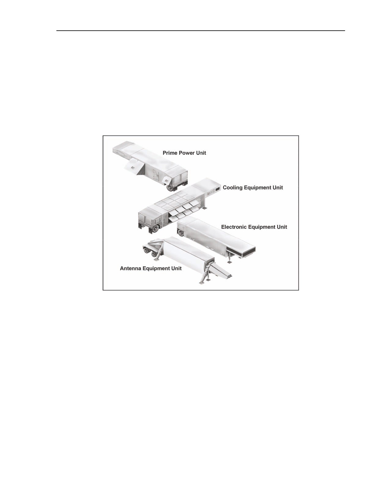
Terminal High-Altitude Area Defense
Cooling Equipment Unit
3-19. The CEU is a fully integrated, transportable trailer system, providing complete system cooling and
power distribution for the THAAD radar system. The CEU transforms and provides power distribution
from the commercial power source or the PPU to the AEU and EEU.
Prime Power Unit
3-20. The PPU is a self-contained transportable engine/alternator system. The primary function of the PPU
is to produce electrical power required to operate the THAAD radar component. The PPU diesel engine
produces power that is transmitted to the cooling equipment unit for distribution to the remaining radar
assemblies.
Figure 3-6. THAAD radar components
PECULIAR SUPPORT EQUIPMENT
3-21. The THAAD peculiar support equipment (PSE) component provides the resources to perform
THAAD unique sustainment maintenance support functions at unit and depot-forward levels. The PSE
hardware consists of a battery support center (BSC) and an interim contractor support system (ICSS). PSE
and common support equipment items include—
z
Prime movers.
z
Generators.
z
Radio sets.
z
Test measurement and diagnostic equipment.
z
Mechanical and electrical support equipment.
Battery Support Center
3-22. The BSC provides a mobile maintenance capability to the THAAD fire units to support remote
maintenance monitoring, telemaintenance, spares management, and mobile support assistance. It consists
of a battery logistics operation center, spares transport trailer, two mobile support trucks, and a deployable
rapid assembly shelter. See Figure 3-7 on the next page.
23 October 2007
FM 3-01.11
3-7
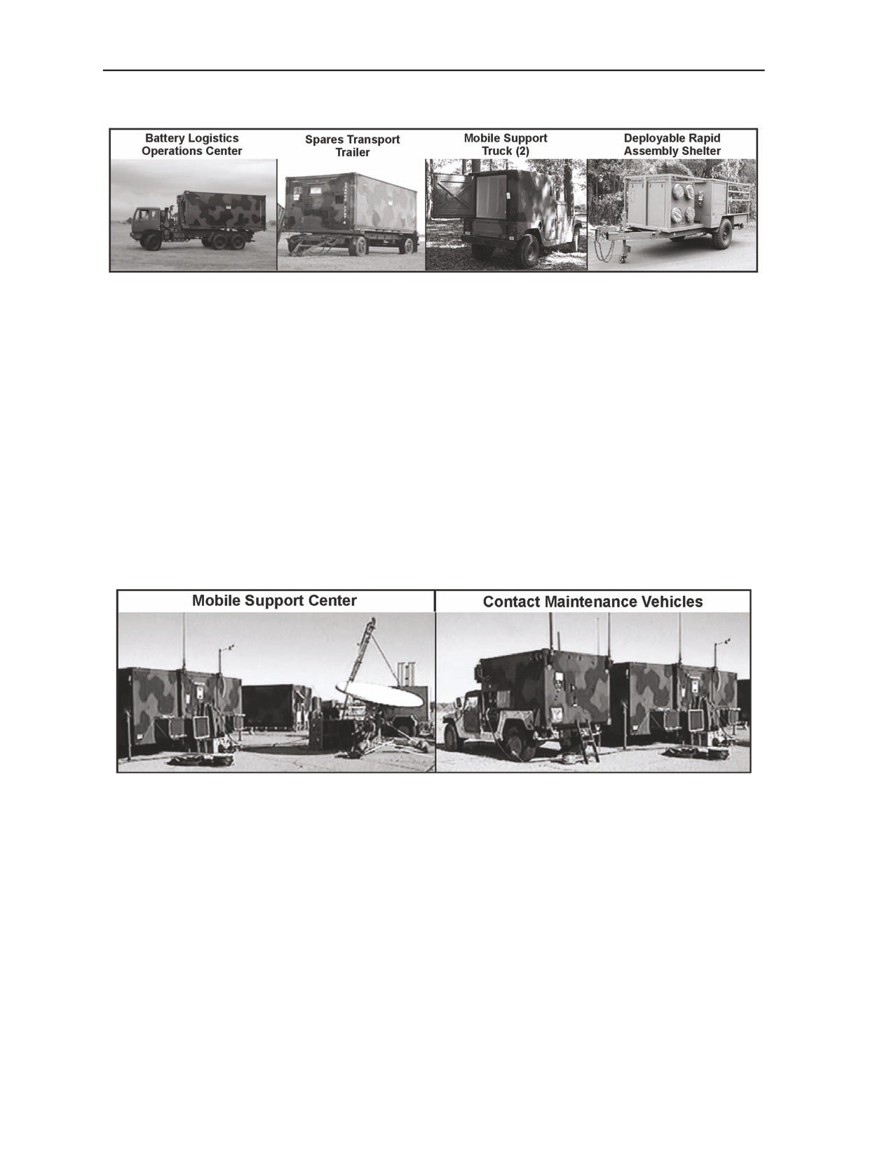
Chapter 3
Figure 3-7. THAAD battery support center
Interim Contractor Support System
3-23. The ICSS shown in Figure 3-8 is designed to support contractor technicians deployed to the theater
of operations as a depot-forward support cell. The ICSS is a modular support package capable of being
responsive to the changing logistical needs of the deployed force. Depending upon mission needs, the ICSS
can easily integrate into an intermediate support base and push forward support as needed through a larger
distribution-based logistics system or rapidly move directly into theater and begin immediate sustainment
operations under even the most spartan conditions. It provides in-theater storage and distribution of spare
and repair parts, tools, test equipment, satellite communications capability for telemaintenance, video
teleconferencing, radar file transfer via the data reduction network, Nonsecure Internet Protocol Router
Network/Secret Internet Protocol Router Network connectivity, and remote supply and support
functionality. It consists of a spares/communications transport shelter as well as a mobile support center
and contact maintenance vehicles. The ICSS is not part of a modified table of organization and equipment.
It will not be issued to the Government.
Figure 3-8. Interim contractor support system
3-8
FM 3-01.11
23 October 2007
Chapter 4
ADA Composite Battalion
This chapter discusses the ADA composite battalion and how it contributes to theater
counter air operations. Missile defense protects the force and critical assets from
attack by theater missiles, which include BMs, CMs, air-to-surface missiles, and large
caliber rockets. This chapter discusses the organization of the ADA composite
battalion, ADA planning overview, ADATF operations, and the ADA fire control
officer (ADAFCO) in his role in the ADA composite battalion.
MISSION
4-1. The mission of the ADA composite battalion is to provide critical air and missile defense coverage
and timely early warning to multiple defended assets and maneuver units across the battlefield to allow
freedom of maneuver and operations in a JIM environment.
STRUCTURE
4-2. ADA brigades are assigned to divisions and corps to protect against theater missile attacks. Patriot
batteries are task-organized with Avenger units, forming an ADA composite battalion. ADA battalions are
deployed as modular, scalable, mission-tailored task forces that may consist of platoon, battery, or
battalion-sized elements. Plans are developed with contingencies for different sized and configured ADA
task forces, as dictated by mission requirements. As combat theaters mature, additional modules of TF
elements may be added to meet changing mission, enemy, terrain and weather, troops and support
available, time available, civil considerations
(METT-TC) requirements and to tailor the TF to the
employment principles of mass, mix, mobility, and integration. The ADA composite battalion is organized
to meet Army Command, Army Service Component Command, and Direct Reporting Unit or
brigade/brigade combat team (BCT) commander directives to accomplish the mission. The ADA composite
battalion will organize according to METT-TC factors, the commander’s intent, and the situation.
4-3. The ADA composite battalion currently consists of four Patriot firing batteries, one Avenger firing
battery, one HHB and one organic maintenance company. One Patriot firing battery consists of six LSs,
one RS, and one ECS. The ADA composite battalion has six Sentinel radars (two in HHB and four in the
Avenger battery), and 24 Avenger fire units in the Avenger firing battery comprising three platoons. The
firing batteries are controlled by the fire coordination center (FCC) to provide an effective and versatile
combination of system capabilities with 360-degree coverage for a seamless air and missile defense while
enhancing force protection capabilities. Organic to the battalion is a maintenance company capable of field
level maintenance. The organization requires leaders who are oriented towards fighting air and missile
battles in the joint operational environment. Figure 4-1 shows an example of an ADA composite battalion
organization.
Contents
Mission
4-1
ADA Planning Overview
4-4
ADA Task Force Operations
4-4
ADA Fire Control Officer
4-8
23 October 2007
FM 3-01.11
4-1

Chapter 4
Figure 4-1. ADA composite battalion organization (example)
Headquarters and Headquarters Battery
4-4. The HHB provides command, control, staff planning, and supervision of battalion operations. It also
provides logistical support, unit level health support, and missile resupply operations for the firing
batteries. It provides unit maintenance on all assigned equipment except communications, communications
security (COMSEC), air traffic control, environmental, and quartermaster equipment. The HHB has a force
protection section assigned to conduct coordinated defense of the unit area or unit movements and to
provide force protection to subordinate units and missions. The HHB operates the TCS, ICC, and battalion
FCC. Figure 4-2 illustrates an example of an ADA composite battalion HHB.
Figure 4-2. ADA composite battalion HHB (example)
Patriot Battery
4-5. The ADA composite battalion currently has four Patriot batteries assigned. Figure 4-3 illustrates an
example of an ADA composite battalion Patriot battery. Each battery provides command and control for
employment and firing of six Patriot launchers, operations of the ECS, and provides battery logistical and
ammunition resupply support. The Patriot battery relies on the ADA composite battalion HHB for unit
4-2
FM 3-01.11
23 October 2007

ADA Composite Battalion
administration, combat health support, religious support, food service support, communications, and
quartermaster support.
Figure 4-3. ADA composite battalion Patriot battery (example)
Avenger Battery
4-6. The ADA composite battalion currently has one Avenger battery assigned. Figure 4-4 illustrates an
example of an ADA composite battalion Avenger battery. The Avenger battery provides command and
control for the employment and firing of 24 Avenger systems plus four Sentinel radars, and provides
battery logistical and ammunition resupply support. The Avenger battery relies on the ADA composite
battalion HHB for unit administration, combat health support, religious support, food service support,
communications, and quartermaster supply.
Figure 4-4. ADA composite battalion Avenger battery (example)
23 October 2007
FM 3-01.11
4-3

Chapter 4
ADA PLANNING OVERVIEW
4-7. ADA planning involves joint, multinational, and Army units including the joint forces command,
service or functional component commands, Army Air and Missile Defense Command, the corps, the ADA
brigades, and the ADA battalions and batteries. At each level of command, planning begins with the
receipt of a mission from higher headquarters and culminates in the issuance of an operations plan, which
provides planning direction to subordinate commands. The designation “plan” is usually used instead of
“order” in preparing for operations well in advance. An operation plan may be put into effect at a
prescribed time, or on signal. It then becomes the operation order.
4-8. ADA planning is performed concurrently at all echelons, a process known as “parallel planning.”
The planning process performed at each echelon as well as the planning products exchanged between
echelons is summarized in the paragraphs below.
ADA TASK FORCE OPERATIONS
4-9. In theaters where the threat includes a mix of MRBMs, SRBMs, other TMs, and aircraft, an ADATF
may be employed to protect forces and high-value assets. An ADATF can be comprised of a THAAD
battery and an ADA composite battalion under the control of a task force TOC (Patriot ICC/TCS), as
shown in Figure 4-5. The ADATF may also include Avenger units.
Figure 4-5. ADATF organization (example)
4-10. The primary advantage of an ADATF is that it provides a higher level of protection than is
achievable with a single system. The THAAD and PAC-3 weapon systems will provide a two-tier defense
for high-value assets located under their protective envelope that denies the enemy a preferred attack
option. THAAD provides the upper-tier defense against MRBMs and is needed to provide near-leak-proof
defense against SRBMs in the common target set, while Patriot provides the lower-tier defense against
SRBMs, other tactical missiles (CMs and ASMs), and aircraft. TBM tracks are handed off to the lower tier
by THAAD in time for Patriot to engage at optimum range and altitude, and to obtain an intercept above a
prescribed keep-out altitude, minimizing the effects of weapons of mass destruction. Avenger units
supplement lower-tier defenses by providing additional protection against low-altitude FW, RW, UA, and
CM threats. The Patriot battalion normally provides the task force command and control.
DEFENSE DESIGN PLANNING CONSIDERATIONS
4-11. To properly implement an ADATF, task force planners should have a detailed knowledge of the
threat. They must also understand the capabilities and limitations of all systems that comprise the task force
and have a working knowledge of THAAD, Patriot, and Avenger units’ system software and
communications. Planners should refer to applicable manuals for technical details and specifics on system
performance and software capabilities and limitations.
4-4
FM 3-01.11
23 October 2007
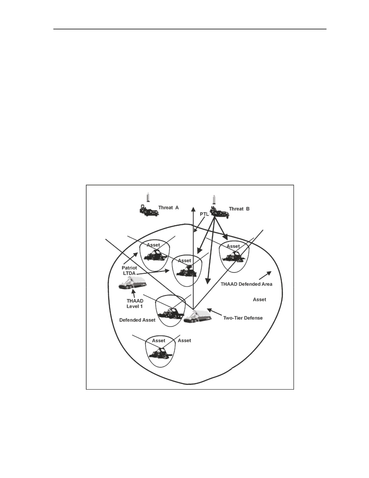
ADA Composite Battalion
4-12. The task force will normally receive the mission, defense priorities, and commander’s intent from
higher headquarters. After assessing METT-TC and developing a detailed intelligence preparation of the
operational environment, planners develop level of protection requirements, taking into consideration the
joint force commander’s defended asset list and criticality, vulnerability, and threat assessments. The level
of protection requirements drives the allocation and positioning of resources as well as system
initialization, firing doctrine, and integration of fires.
4-13. TF planning requires cooperation and close coordination among Patriot, THAAD, and Avenger unit
planners. In planning TF defenses, THAAD defense design is first developed. This involves determining
the upper-tier search requirements, establishing the primary target lines (PTLs), determining the optimum
FU location, emplacing the radar and launchers, and planning communications links within and external to
the THAAD battery, including linkage with the ADATF TOC. Planners next develop the Patriot defense
design, which involves determining the lower-tier search requirements, establishing PTLs, emplacement of
the radar, LCSs and launchers, and planning communications links within and external to the Patriot
battalion.
4-14. This planning results in an ADATF defense design, as illustrated in Figure 4-6. This example shows
five Patriot FUs and a THAAD FU. The THAAD FU is capable of defending selected assets against
MRBMs and most SRBMs. Normally, THAAD is initialized to protect the lower-tier Patriot FUs.
Figure 4-6. ADATF defense design considerations (example)
4-15. The Patriot FUs are capable of defending selected assets within their respective lower-tier defended
areas (LTDAs). An LTDA is defined as a two-dimensional, multisided area that represents a region where
Patriot has both defended assets and engagement capability against TBMs. LTDA coverage is a function of
23 October 2007
FM 3-01.11
4-5

Chapter 4
a number of factors including the type of threat, threat location, threat attack vectors, FU PTLs, Patriot
missile type, and remote launcher placement. An LTDA can be extended or enlarged using Patriot’s RL-3
remote launch capability.
COMMUNICATIONS
4-16. The Patriot battalion may be task-organized with THAAD and/or Avenger units, forming ADATF.
The ADATF uses a variety of communications networks to accomplish its mission. These networks, shown
in Figure 4-7, include the joint data network (JDN), the joint engagement coordination network (JECN),
the joint mission management network (JMMN), and UHF and other voice nets. The JDN, JECN, and
JMMN are Joint Tactical Information Distribution System
(JTIDS) communications networks that
disseminate TADIL-J data messages.
Figure 4-7. ADATF communications networks
Joint Data Network
4-17. The JDN is used to disseminate near-real-time surveillance and precise participant location
information. It is used by the ADATF primarily for exchanging air and missile track data. The specific
messages used in ADATF operations are shown in Figure 4-8. These messages are associated with network
participation groups (NPGs) 6.7. (See CJCSM 6120.01D for discussion of NPGs and TADIL-J messages.)
Joint Engagement Coordination Network
4-18. The JECN is used to disseminate near-real-time engagement coordination information. It is used by
the ADATF primarily to coordinate engagements between Patriot and THAAD. The specific messages
used by the ADATF are associated with Patriot external communications.
Joint Mission Management Network
4-19. The JMMN is used to disseminate near-real-time mission management information. It is used by the
ADATF and THAAD to disseminate commands, engagement status, and ICC/ECS operational status. It
also serves as a C2 link with higher headquarters and joint agencies.
4-6
FM 3-01.11
23 October 2007

ADA Composite Battalion
Figure 4-8. JDN, JECN, and JMMN
UHF Voice, ACUS, and SINCGARS Nets
4-20. The UHF voice net, shown in Figure 4-9, provides the primary communications for coordinating
ADATF engagement and force operations activities, including engagement coordination, defense design,
firing doctrine, system initialization, and sensor orientation, with TF elements. The SINCGARS net is a
frequency modulation (FM) net used for backup C2 within the ADATF. The area common user system
(ACUS) net is also used to coordinate force and engagement operations activities.
Figure 4-9. Mobile subscriber equipment and voice nets
Commander’s Tactical Terminal-Hybrid
4-21. A commander’s tactical terminal-hybrid (CTT-H) is installed in the TCS and ICC. The CTT-H is a
special purpose receiver that allows Patriot to receive intelligence information from various intelligence
23 October 2007
FM 3-01.11
4-7
Chapter 4
sources within theater. The CTT-H allows tactical information broadcast service (TIBS) data to be
displayed in the TCS and ICC for SA and planning purposes.
ADA FIRE CONTROL OFFICER
4-22. The ADAFCO is responsible to the senior director for coordinating air defense of designated
facilities and areas. He is also responsible for coordinating and monitoring the command, air picture, and
fire unit exchange between the control and reporting center/Airborne Warning and Control System
(AWACS)/Aegis/tactical air operations center and the Patriot ICC or the ADA battalion FCC.
4-23. An ADAFCO is required in any regional/sector air defense command in which an Army air and
missile defense capability is employed. The ADAFCO has the expertise to advise the regional air defense
commander (RADC)/sector air defense commander (SADC) on what course of action Army AD units
would likely follow during nonstandard situations, especially with degraded communications, what
limitations rules of engagement can have on autonomous Army ADA units, what tactics may be more
effective, et cetera. ADAFCO elements should be part of liaison to any of the Service AMD operations
centers that may have control of or support from Army ADA assets. Typically, an ADAFCO element
deploys to the appropriate air defense region or sector location and is responsible to the RADC/SADC for
integrating Army AMD capabilities into that part of the Integrated Air Defense System. The ADAFCO
must have access to dedicated AD communications links (for example, dedicated AD voice circuit) and
with Army AD C2 nodes when conducting active air defense operations. Unless very unusual
circumstances dictate, an ADAFCO should not be placed on an airborne warning and control/airborne
command and control aircraft that is not a full-time SADC directing ground-based AD in conjunction with
active air intercepts. Those aircraft normally lack dedicated seat positions and communications for the
ADAFCO and do not have as reliable SA available as does a RADC/SADC with a tactical data link and a
common tactical picture or a common operational picture (COP).
4-8
FM 3-01.11
23 October 2007
Appendix A
Sentinel Radar Systems
This chapter describes the Sentinel radar sensor systems, AN/MPQ-64, and Improved
Sentinel, AN/MPQ-64A1, and their role as air defense surveillance and target
acquisition/tracking sensors for ADA weapons in the division and corps area. The
Sentinel also sends air tracks to the ADAM cell to provide early warning. The
Sentinel’s accurate and quick-reacting capability enables ADA weapon systems to
acquire targets sufficiently beyond the forward line of own troops, thus reducing
reaction time and allowing engagement at optimum range.
MISSION
A-1. Sentinel’s mission is to alert, or cue, the Patriot, Avenger, and MANPADS Stinger teams of hostile
aircraft, to protect forces from fratricide, and to provide an air picture and situational data to the C2 centers.
Sentinel contributes to the digital battlefield by automatically detecting, tracking, classifying, identifying,
and reporting targets infiltrating below the umbrella provided by long and medium air defense sensors.
A-2. The Sentinel is deployed with FAAD units of the U.S. Army and U.S. Marine Corps. It is a mobile,
compact, modular, multifunctional phased-array radar. The Sentinel is designed with high resistance to
ECM capabilities, and performs target acquisition, tracking, and identification.
DESCRIPTION
A-3. The Sentinel consists of a radar antenna unit mounted on top of the transceiver unit. The radar
antenna unit also includes an IFF interrogator, an IFF antenna, and an auxiliary ECCM antenna mounted
on a single pedestal that rotates during operation. The antenna unit is lowered by hand crank to the stowed
position for road march.
A-4. The Sentinel is a state-of-the-art three-dimensional (3-D) battlefield radar sensor using modern
phased-array antenna technology and IFF system for interfacing with the FAAD C2 network. Targets can
be hovering to fast-moving, or nap-of-the-earth, out to the maximum engagement altitude of the FAAD
weapons. Highly mobile and reliable, the Sentinel’s antiradiation missile and ECM support the Army corps
and divisional AD operations across the full spectrum of conflict.
A-5. Sentinel is designed to operate in clear and obscured conditions, day or night operations, adverse
weather, dust, smoke, aerosols, precipitation clutter environments and countermeasures, while providing
360-degree azimuth coverage for acquisition and tracking.
A-6. Sentinel's integrated IFF reduces the potential for fratricide of Army Aviation and Air Force aircraft.
An auxiliary ECCM antenna is mounted on a single pedestal that rotates during operation. The antenna unit
is lowered by hand crank to the stowed position for road march.
SUPPORT EQUIPMENT
A-7. The HMMWV is the prime mover and support vehicle for the Sentinel. The HMMWV transports the
tactically quiet 10-kw generator, communications equipment, cabling for system power, team tactical gear,
water, and rations as shown in Figure A-1. The HMMWV can meet the fuel requirement needs of the 10-
kw generator for extended periods of operations by transferring fuel from vehicle to generator by the
generator on-board fuel selection switch.
23 October 2007
FM 3-01.11
A-1
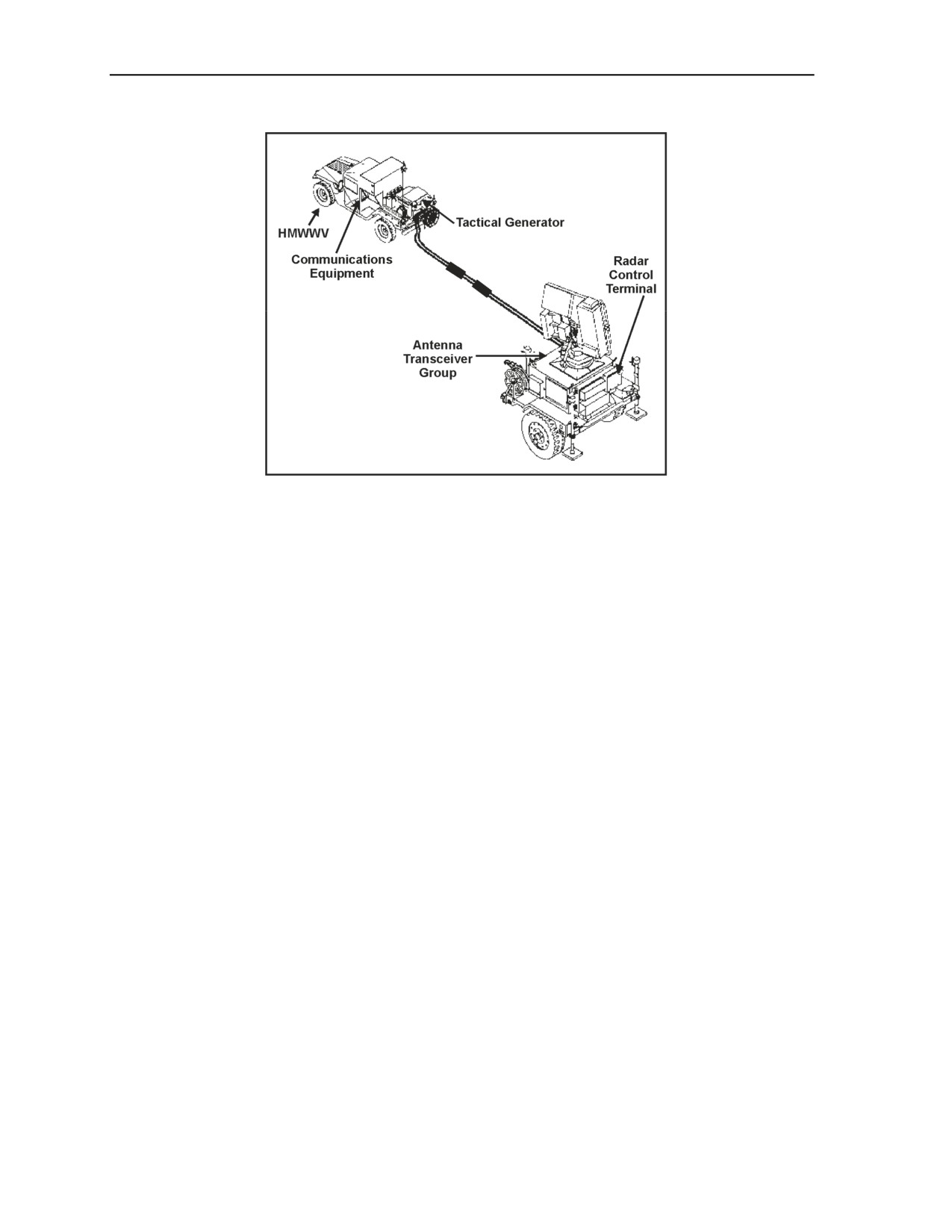
Appendix A
Figure A-1. Sentinel radar sensor system
A-8. The remote control terminal (RCT) is a rugged, compact mini-computer with a graphic display
screen and multifunction control input keyboard. The Sentinel operator controls the operation of the radar
by use of the keypads on the RCT. The RCT can be cable-remoted from the Sentinel to provide real-time
tactical air pictures on a graphic display screen at remote locations. Sentinel radar target tracks are
displayed to the operator in target symbology that shows range, elevation, velocity, and track number
information.
OPERATING CHARACTERISTICS
A-9. The Sentinel has a search elevation capability of 20- to 25-degree scan and is selectable between -15
and +55 degrees. It can rotate in azimuth 360 degrees clockwise (cw) or counterclockwise (ccw) scan and
search a perimeter greater than 40 km. The elevation azimuth beam width track perimeter is -10 through
+55 degrees with a 360-degree cw or ccw scan 2- by 2-degree pencil beam 40-km instrumented range.
A-10. The Sentinel is capable of reporting track data as listed below:
z
Target tracking in azimuth, elevation, and headings in degrees.
z
Ranges in miles or kilometers.
z
Altitudes in feet or meters.
z
Velocity in feet per second or meters per second.
z
Target discrimination, fixed-wing or helicopter unknown, designation.
z
Unknown or unknown friendly.
z
Jammer discrimination in azimuth, and elevation in degrees or mils.
z
Report reference data respective to data link reference point or site Military Grid Reference
System/mean sea level.
z
Coordinates report capabilities FAAD C2 and intelligence activities data link to include track
report and IFF/selective identification feature report.
z
ECM intercept messages over EPLRS radio link to include track report messages via
SINCGARS radio link and track report messages.
A-11. The Sentinel operates in the X Band with a 3-D pencil beam and range-gated, pulse Doppler radar.
A-2
FM 3-01.11
23 October 2007
Sentinel Radar Systems
A-12. The FAAD data link (FDL) interfaces with SINCGARS along with the EPLRS PLGR/JTIDS hybrid
interface and is hardwired to command and control.
RADIO FREQUENCY HAZARD
A-13. An RF radiation hazard condition exists for fixed-beam operation
(antenna not rotating). No
personnel will be within 800 mils left or right of frontal area of antenna for a distance of 50 meters when
system is radiating while not rotating.
RADAR SENSOR CHARACTERISTICS
A-14. Sentinel’s characteristics are shown in Table A-1.
Table A-1. Sentinel characteristics
Height
Antenna erected
131.7 in
Antenna stowed
94.8 in
Width
Mirrors folded
85 in
Length
167.26 in
Length with HMMWV
312 in
Weight
3,740 lb
Temperature
Operating
-50° to 125° F (-46° to 52° C)
Non-operating
-70° to 160° F (-57° to 71° C)
Altitude
Operating
Up to 10,000 ft
Non-operating
Up to 50,000 ft
Weather
Wind velocity:
Operating
0 to 52 mph with gusts to 75 mph
Non-operating
52 mph with gusts to 100 mph
Rain
5 in/hr
Electrical Requirements
Voltage
208 VAC + 10% 3-phase; 120 VAC + 10%
Power
10 kw, 400 Hz
Mobility/Transportability
Graded gravel road
30 mph
Cross-country terrain
8 mph
Side slope
20%
Longitudinal slope
32%
Fording
up to 30 in deep
METHODS OF EMPLOYMENT (A AND B)
A-15. Method A: Sensor sections are deployed by the sensor platoon leader with staff supervision
exercised by the AD battalion S-3. The S-3 coordinates the selected map positions with the division AC2
cell. In this method, the platoon leader retains control of the sections.
23 October 2007
FM 3-01.11
A-3