Siemens SITRANS P. Operating Instructions (2019) - page 7
Technical data
13.10 Certificates and approvals
Explosion protection in accordance with ATEX
● Type of protection for Zone 2
A power supply unit of intrinsically safe protection
type "Ex ia" in zone 2 is sufficient to connect devices
of intrinsically safe protection type [Ex ic].
Designation
II 3G Ex ec IIC T4/T6 Gc
Permissible ambient temperature "ec"
-40 … +80 °C (-40 … +176 °F) temperature class T4
-40 … +40 °C (-40 … +104 °F) temperature class T6
Permissible temperature of medium
-40 … +100 °C (-40 … +212 °F) temperature class T4
-40 … +70 °C (-40 … +158 °F) temperature class T6
Connection "ec"
To a circuit with the operating values:
Un = 10.5 to 30 V, 4 ... 20 mA
SITRANS P320/P420 with 4 to 20 mA/HART
240

Technical data
13.10 Certificates and approvals
Explosion protection in accordance with FM (USA)
FM19US0155X
The permissible operating values can be found in the certificate.
Order variants
Identification
7MF0..0-
-.B..-Z
Class I, Zone 0, AEx ia llC T4/T6 Ga
Class I, Zone 1, AEx ib llC T4/T6 Gb
lntrinsically Safe (lS) for Class l, DIV 1, Gr. A-D
7MF0..0-
-.C..-Z
Class l, Zone 0/1, AEx ia/db llC T4/T6 Ga/Gb
Explosion Proof (XP) for Class l, DIV 1, Gr. A-D
7MF0..0-
-.D..-Z
Class I, Zone 0, AEx ia llC T4/T6 Ga
Class l, Zone 0/1, AEx ia/db llC T4/T6 Ga/Gb
lntrinsically Safe (lS) for Class I, DIV 1, Gr. A-D
Explosion Proof (XP) for Class l, DIV 1, Gr. A-D
7MF0..0-
-.L..-Z
Class ll, Zone 21, AEx tb lllC T120°C Db
Class ll, Zone 22, AEx tc lllG T120°C Dc
Class l, Zone 2, AEx ec llC T4/T6 Gc
Dust lgnition Proof (DlP) for Class ll, DIV 2, Gr. E-G, Class lll
Non incendive (NI) for Class I, DIV 2, Gr. A-D
7MF0..0-
-.M..-Z
Class ll, Zone 20, AEx ia lllC T120°C Da
Class l, Zone 0, AEx ia llC T4/T6 Ga
Class ll, Zone 21, AEx tb lllC T120°C Db
Class l, Zone 2, AEx ec llC T4/T6 Gc
lntrinsically Safe (lS) for Class ll, DIV 1, Gr. E-G; Class lll
lntrinsically Safe (lS) for Class l, DIV 1 Gr. A-D
Dust lgnition Proof (DlP) for Class ll, DIV 2, Gr. E-G; Class lll
Non incendive (Nl) for Class l, DIV 2, Gr. A-D
7MF0..0-
-.S..-Z
Class l, Zone 0/1, AEx ia/db llC T4/T6 Ga/Gb
Class l, Zone 0, AEx ia llC T4/T6 Ga
Class ll, Zone 21, AEx tb lllC T120°C Db
Class l, Zone 2, AEx ec llC T4/T6 Gc
7MF0..0-
-.T..-Z
Class l, Zone 0/1, AEx ia/db llC T4/T6 Ga/Gb
Class l, Zone 0, AEx ia llC T4/T6 Ga
Class ll, Zone 21, AEx tb lllC T120°C Db
Class l, Zone 2, AEx ec llC T4/T6 Gc
Explosion proof (XP) for Class I, DIV 1 Gr. A-D
lntrinsically Safe (lS) for Class l, DIV 1 Gr. A-D
Dust ignition proof (DlP) for Class ll, DIV 2, Gr. E-G; Class lll
Non-incendive (Nl) for Class l, DIV 2, Gr. A-D
SITRANS P320/P420 with 4 to 20 mA/HART
241

Technical data
13.10 Certificates and approvals
Explosion protection in accordance with FM (USA)
Special conditions for use
● For type of protection "db": When you use the device as partition wall device in zones that require EPL Ga, isolate the non-
intrinsically safe circuit safely from ground, e.g.: through a SELV circuit.
● For type of protection "ec": Isolate the non-intrinsically safe circuit safely from ground, e.g.: through a SELV circuit that
ensures transient protection up to 140% of the nominal voltage.
● Mount the device so that the enclosure is not exposed to any intense electrostatic charging processes.
● To prevent electrostatic charging in hazardous areas, clean the outside of the enclosure using a cloth moistened with
water.
Explosion protection in accordance with cCSAus (Canada/USA)
CSA18CA70163103X
The permissible operating values can be found in the certificate.
Marking (XP/DIP) or (IS); (NI)
According to CSA Ex ia/db IIC T4/T6 Ga/Gb
Standards
Ex ia IIC T4/T6 Ga
Ex ia IIIC T120°C Da
Ex tb IIIC T120°C Db
Ex ec IIC T4/T6 Gc
Class I, DIV 1, Gr. A-D (Explosion Proof)
Intrinsically Safe (IS) for Class I, DIV 1, Gr. A-D
(Intrinsically Safe (IS))
Class II, DIV 2, Gr. E-G; Class III
Class I, DIV 2, Gr. A-D (NI)
According to US
Class I, Zone 0/1, AEx ia/db IIC T4/T6 Ga/Gb
Standards
Class I, Zone 0, AEx ia IIC T4/T6 Ga
Zone 20, AEx ia IIIC T120°C Da
Zone 21, A/Ex tb IIIC T120°C Db
Class I, Zone 2, AEx ec IIC T4/T6 Gc
Class I, DIV 1 Gr. A-D (Explosion proof (XP))
Class I, DIV 1 Gr. A-D (Intrinsically Safe (IS))
Class II, DIV 2, Gr. E-G; Class III
Class I, DIV 2, Gr. A-D (NI)
Further certificates for explosion protection
Explosion protection in accordance with NEPSI (China)
The permissible operating values and markings can be found in the
certificate.
GYJ19.1058X
Explosion protection in accordance with INMETRO
(Brasil)
BRA-18-GE-0035X
Explosion protection in accordance with EAC (Russia)
TC RU C-DE.AA87.B.01202
Explosion protection in accordance with IECEx
IECEx BVS 18.0038X
SITRANS P320/P420 with 4 to 20 mA/HART
242

Dimension drawings
14
14.1
SITRANS P320/P420 for gauge pressure and absolute pressure from
the gauge pressure series
5
1
approx. 96 (3.78)
17 (0.67)
2
6
7
3
4
3
9
6:
8
PLQ
105 (4.13)
① Electronics side, display
(longer for cover with glass pane)1)
② Connection end
③ Electrical connection:
● M20 x 1.5 gland3)
●
½-14 NPT gland
● Han 7D/Han 8D plug2) 3)
● M12 connector2)3)
④ Harting adapter
⑤ Cover over buttons and nameplate with general information
⑥ Blanking plug
⑦ Safety catch
(only for flameproof enclosure)
⑧ Process connection: G½B connection pin or oval flange
⑨ Mounting bracket (optional)
1)
In addition, allow approx. 22 mm (0.87 inch) for the thread length when removing the covers
SITRANS P320/P420 with 4 to 20 mA/HART
243
Dimension drawings
14.1 SITRANS P320/P420 for gauge pressure and absolute pressure from the gauge pressure series
2)
Not with "flameproof enclosure" type of protection
3)
Not for "FM + CSA [is + XP]" type of protection
Figure 14-1
SITRANS P320 and SITRANS P420 pressure transmitters for absolute pressure, from the gauge pressure
series, dimensions in mm (inches)
SITRANS P320/P420 with 4 to 20 mA/HART
244

Dimension drawings
14.2 SITRANS P320/P420 for differential pressure, gauge pressure, flow and absolute pressure from the
differential pressure series
14.2
SITRANS P320/P420 for differential pressure, gauge pressure, flow
and absolute pressure from the differential pressure series
5
1
6
3
7
2
8
12
PLQ
9
11
10
DSSUR[
3
4
①
Electronics side, display
(longer for cover with glass pane)1)
②
Connection end
③
Electrical connection:
● M20 x 1.5 gland
●
½-14 NPT gland
● Han 7D/Han 8D plug2) 3)
● M12 connector2)3)
④
Harting adapter
⑤
Cover over buttons and nameplate with general information
⑥
Blanking plug
⑦
Safety catch
(only for "flameproof enclosure" type of protection)
⑧
Lateral ventilation for liquid measurement (standard)
⑨
Lateral ventilation for gas measurement (order option "K85")
⑩
Mounting bracket (optional)
⑪
Sealing plug, with valve (optional)
⑫
Process connection: 1/4-18 NPT (EN 61518)
1)
In addition, allow approx. 22 mm (0.87 inch) for the thread length when removing the covers
2)
Not with "flameproof enclosure" type of protection
3)
Not for "FM + CSA [IS + XP]" type of protection
SITRANS P320/P420 with 4 to 20 mA/HART
245

Dimension drawings
14.2 SITRANS P320/P420 for differential pressure, gauge pressure, flow and absolute pressure from the
differential pressure series
Figure 14-2
SITRANS P320 and SITRANS P420 pressure transmitters for differential pressure and flow, dimensions in mm
(inches)
5
2.6
146 (5.75)
(0.1)
61 (2.4)
approx. 96 (3.78)
17 (0.67)
27 (1.06)
84 (3.31)
1
6
7
3
4
3
2
min. 92 (3.6)
8
8
10
9
60 (2.36)4)
approx. 85 (3.35)
65 (2.56)
①
Electronics side, display
(longer for cover with inspection window)1)
②
Connection end
③
Electrical connection:
● M20 x 1.5 gland
●
½-14 NPT gland
● Han 7D/Han 8D plug2)3
● M12 connector2)3)
④
Harting adapter
⑤
Cover over buttons and nameplate with general information
⑥
Blanking plug
⑦
Safety catch
(only for "flameproof enclosure" type of protection)
⑧
Sealing plug, with valve (optional)
⑨
Process connection: ¼-18 NPT (IEC 61518)
⑩
Clearance for rotating the enclosure
1)
In addition, allow approx. 22 mm (0.87 inch) for the thread length when removing the covers
2)
Not with "flameproof enclosure" type of protection
3)
Not for "FM + CSA [is + XP]" type of protection
4)
74 mm (2.9 inch) for PN ≥ 420 (MAWP ≥ 6092 psi)
5)
91 mm (3.6 inch) for PN ≥ 420 (MAWP ≥ 6092 psi)
6)
226 mm (8.62 inch) for PN ≥ 420 (MAWP ≥ 6092 psi)
Figure 14-3
SITRANS P320 and SITRANS P420 pressure transmitters for differential pressure and flow with process flanges
for vertical pressure lines (order option "K81"), dimensions in mm (inches)
SITRANS P320/P420 with 4 to 20 mA/HART
246

Dimension drawings
14.3 SITRANS P 320/P420 for level
14.3
SITRANS P 320/P420 for level
2
27 (1.06)
84 (3.31)
29 (1.14)
146 (5.75)
74 (2.31)
61 (2.4)
3
5
6
4
1
135 (5.31)
min. 92 (3.62)
7
54 (2.13)
108 (4.25)
n x d2
approx. 96 (3.78)
17 (0.67)
1
8
① Electrical connection:
● M20 x 1.5 gland
●
½-14 NPT gland
● Han 7D/Han 8D plug2) 3)
● M12 connector2)3)
② Cover over buttons and nameplate with general information
③ Blanking plug
④ Safety catch
(only for "flameproof enclosure" type of protection)
⑤ Connection end
⑥ Electronics side, display
(longer for cover with glass pane)1)
⑦ Locking screw
⑧ Harting adapter
1)
In addition, allow approx. 22 mm (0.87 inch) for the thread length when removing the covers
SITRANS P320/P420 with 4 to 20 mA/HART
247
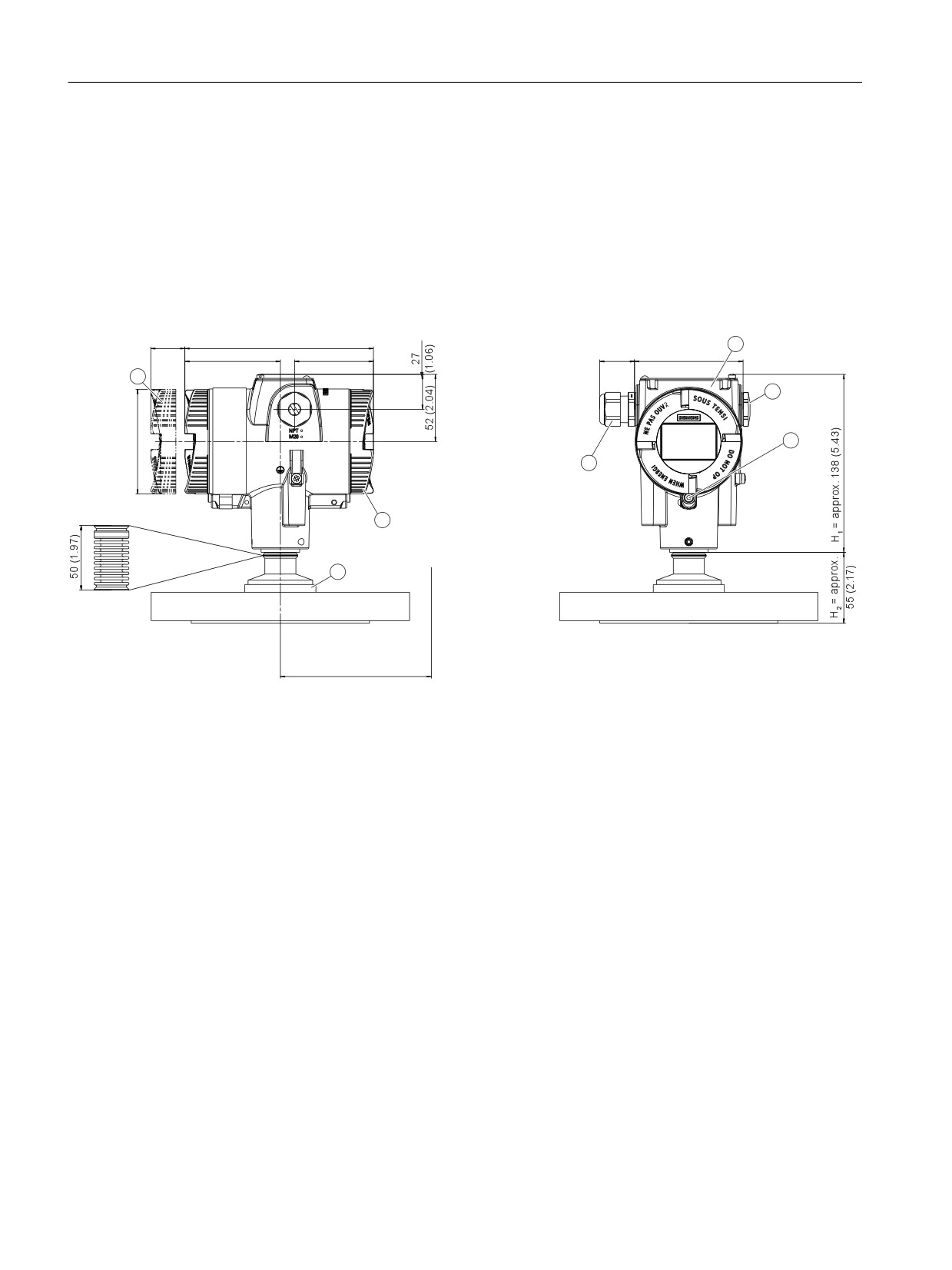
Dimension drawings
14.4 SITRANS P320/P420 (front-flush)
2)
Not with "flameproof enclosure" type of protection
3)
Not for "FM + CSA [is + XP]" type of protection
Figure 14-4
SITRANS P320 and SITRANS P420 pressure transmitters for level, including mounting flange, dimensions in
mm (inch)
14.4
SITRANS P320/P420 (front-flush)
2.6
146 (5.74)
4
(0.1)
74 (2.9)
61 (2.4)
27 (1.06)
84 (3.31)
1
5
6
3
2
7
min. 92 (3.6)
①
Electronics side, display
(longer for cover with glass pane)1)
②
Connection end
③
Electrical connection:
● M20 x 1.5 gland
●
½-14 NPT gland
● Han 7D/Han 8D plug2) 3)
● M12 connector2)3)
④
Cover over buttons and nameplate with general information
⑤
Blanking plug
⑥
Safety catch
(only for "flameproof enclosure" type of protection)
⑦
Process connection
1)
In addition, allow approx. 22 mm (0.87 inch) for the thread length when removing the covers
2)
Not with "flameproof enclosure" type of protection
3)
Not for "FM + CSA [is + XP]" type of protection
Figure 14-5
SITRANS P320 and SITRANS P420 pressure transmitters (front-flush), dimensions in mm (inch)
SITRANS P320/P420 with 4 to 20 mA/HART
248

Dimension drawings
14.4 SITRANS P320/P420 (front-flush)
14.4.1
Note 3A and EHDG
Note
Approvals
The references to the approvals for "EHEDG" and "3A" refer to the respective process
connections and are not device-specific. Please refer to the technical specifications of the
respective pressure transmitter to see whether the desired certificate is available for your
device/flange combination.
14.4.2
Connections as per EN and ASME
Flange according to EN
EN 1092-1
DN
PN
⊘D
H2
25
40
115 mm (4.5'')
Approx. 52 mm (2'')
40
40
150 mm (5.9'')
40
100
170 mm (6.7'')
50
16
165 mm (6.5'')
'
50
40
165 mm (6.5'')
80
16
200 mm (7.9'')
80
40
200 mm (7.9'')
Threaded connections
G3/4", G1" and G2" In accordance with DIN 3852
DN
PN
⊘D
H2
¾"
60
37 mm (1.5'')
approx. 45 mm (1.8'')
1"
60
48 mm (1.9'')
approx. 47 mm (1.9'')
2''
60
78 mm (3.1'')
Approx. 52 mm (2'')
'
SITRANS P320/P420 with 4 to 20 mA/HART
249

Dimension drawings
14.4 SITRANS P320/P420 (front-flush)
Flange according to ASME
ASME B 16.5
DN
CLASS
⊘D
H2
1''
150
110 mm (4.3'')
Approx. 52 mm (2'')
1½"
150
125 mm (4.9'')
1½"
300
155 mm (6.1'')
2''
150
150 mm (5.9'')
'
2''
300
165 mm (6.5'')
3''
150
190 mm (7.5'')
3''
300
210 mm (8.1'')
4''
150
230 mm (9.1'')
4''
300
255 mm (10.0'')
14.4.3
F&B and pharma flange
Connections as per DIN
DIN 11851
DN
PN
⊘D
H2
50
25
92 mm (3.6'')
Approx. 52 mm (2'')
80
25
127 mm (5.0'')
'
DIN 11864-1 Form A - sterile threaded sockets
DN
PN
⊘D
H2
50
25
78 mm (2'')
Approx. 52 mm (2'')
65
25
95 mm (3.7'')
80
25
110 mm (4.3'')
100
25
130 mm (5.1'')
'
Approvals
EHEDG
SITRANS P320/P420 with 4 to 20 mA/HART
250
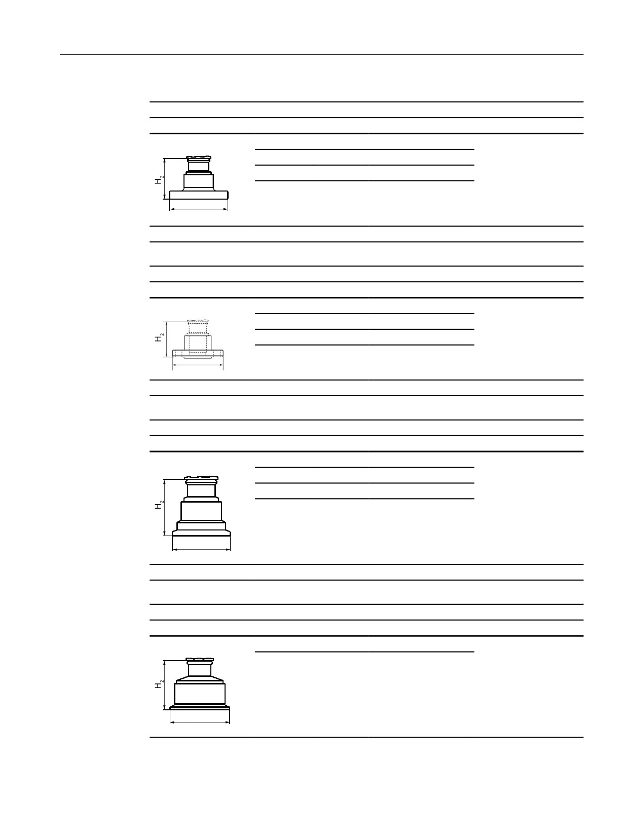
Dimension drawings
14.4 SITRANS P320/P420 (front-flush)
DIN 11864-2 Form A - sterile collar flange
DN
PN
⊘D
H2
50
16
94 mm (3.7'')
Approx. 52 mm (2'')
65
16
113 mm (4.4'')
80
16
133 mm (5.2'')
100
16
159 mm (6.3'')
'
Approvals
EHEDG
DIN 11864-2 Form A - sterile groove flange
DN
PN
⊘D
H2
50
16
94 mm (3.7'')
Approx. 52 mm (2'')
65
16
113 mm (4.4'')
80
16
133 mm (5.2'')
100
16
159 mm (6.3'')
'
Approvals
EHEDG
DIN 11864-3 Form A - sterile collar sockets
DN
PN
⊘D
H2
50
25
77.5 mm (3.1'')
Approx. 52 mm (2'')
65
25
91 mm (3.6'')
80
16
106 mm (4.2'')
100
16
130 mm (5.1'')
'
Approvals
EHEDG
Tri-Clamp as per DIN 32676
DN
PN
⊘D
H2
50
16
64 mm (2.5'')
Approx. 52 mm (2'')
65
16
91 mm (3.6'')
'
SITRANS P320/P420 with 4 to 20 mA/HART
251

Dimension drawings
14.4 SITRANS P320/P420 (front-flush)
Other connections
Varivent® connector
DN
PN
⊘D
H2
40-125
40
84 mm (3.3'')
Approx. 52 mm (2'')
'
Approvals
EHEDG
Connection in accordance with DRD
DN
PN
⊘D
H2
65
40
105 mm (4.1'')
Approx. 52 mm (2'')
'
BioConnectTM connectors
BioConnectTM screwed joint
DN
PN
⊘D
H2
50
16
82 mm (3.2'')
Approx. 52 mm (2'')
65
16
105 mm (4.1'')
80
16
115 mm (4.5'')
100
16
145 mm (5.7'')
2"
16
82 mm (3.2'')
2½"
16
105 mm (4.1'')
'
3"
16
105 mm (4.1'')
4"
16
145 mm (5.7'')
Approvals
EHEDG
SITRANS P320/P420 with 4 to 20 mA/HART
252

Dimension drawings
14.4 SITRANS P320/P420 (front-flush)
BioConnectTM flange connector
DN
PN
⊘D
H2
50
16
110 mm (4.3'')
Approx. 52 mm (2'')
65
16
140 mm (5.5'')
80
16
150 mm (5.9'')
100
16
175 mm (6.9'')
'
2"
16
100 mm (3.9'')
2½"
16
110 mm (4.3'')
3"
16
140 mm (5.5'')
4"
16
175 mm (6.9'')
Approvals
EHEDG
BioConnectTM clamp connector
DN
PN
⊘D
H2
50
16
77.4 mm (3.0")
Approx. 52 mm (2'')
65
10
90.9 mm (3.6'')
80
10
106 mm (4.2'')
100
10
119 mm (4.7'')
2"
16
64 mm (2.5")
2½"
16
77.4 mm (3.0'')
3"
10
90.9 mm (3.6'')
'
4"
10
119 mm (4.7'')
Approvals
EHEDG
Connect STM flanged joint
DN
PN
⊘D
H2
50
16
125 mm (4.9'')
Approx. 52 mm (2'')
65
10
145 mm (5.7'')
80
10
155 mm (6.1'')
100
10
180 mm (7.1'')
'
2"
16
125 mm (4.9'')
2½"
10
135 mm (5.3'')
3"
10
145 mm (5.7'')
4"
10
180 mm (7.1'')
Approvals
EHEDG
SITRANS P320/P420 with 4 to 20 mA/HART
253

Dimension drawings
14.4 SITRANS P320/P420 (front-flush)
Other connections
BioControlTM connector
DN
PN
⊘D
H2
50
16
90 mm (3.5'')
Approx. 52 mm (2'')
65
16
120 mm (4.7'')
'
Approvals
EHEDG
14.4.4
PMC Style
Connections for the paper industry
PMC Style Standard
DN
PN
⊘D
H2
-
-
40.9 mm (1.6'')
Approx. 36.8 mm (1.4'')
M44x1.25 cap nut
'
PMC-Style Minibolt
DN
PN
⊘D
H2
-
-
26.3 mm (1.0'')
Approx. 33.1 mm (1.3'')
'
SITRANS P320/P420 with 4 to 20 mA/HART
254
Dimension drawings
14.4 SITRANS P320/P420 (front-flush)
14.4.5
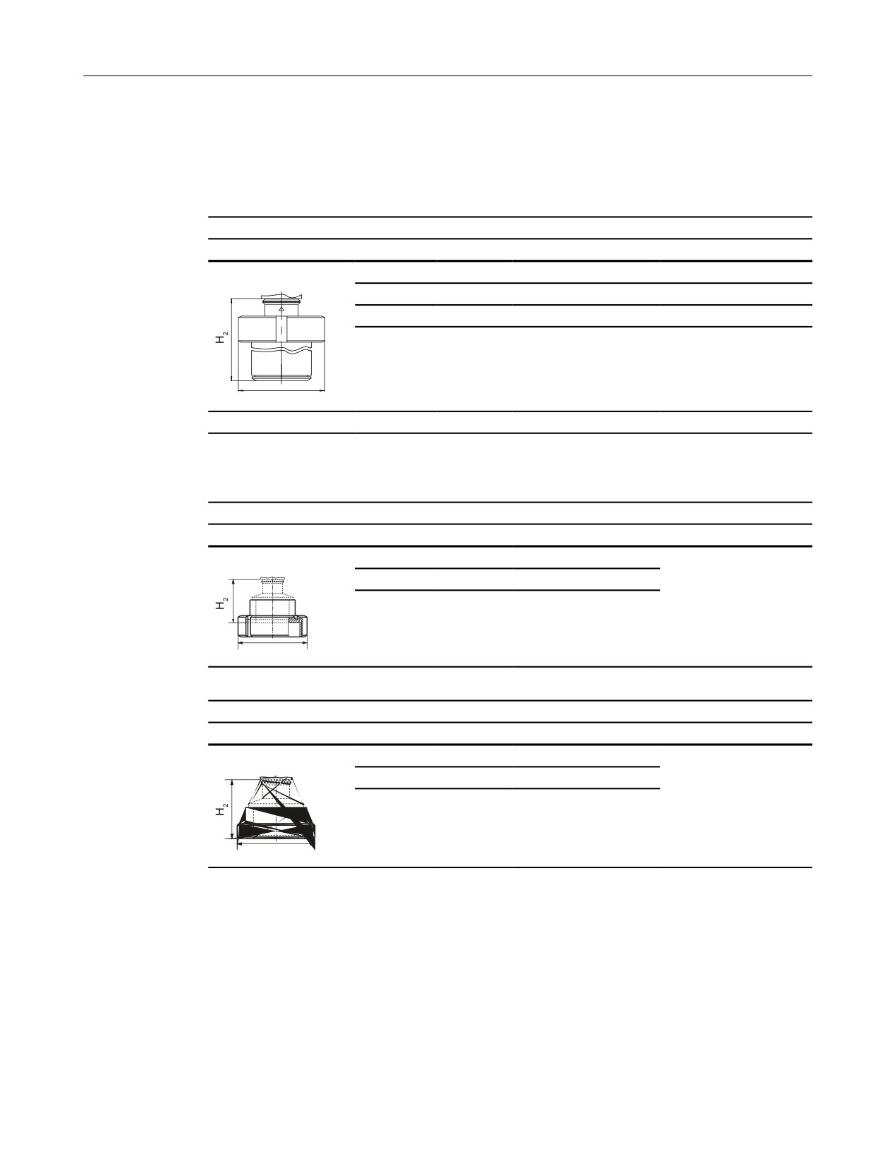
Special connections
Tank connection
TG52/50 and TG52/150
DN
PN
⊘D
H2
TG52/50
25
40
63 mm (2.5'')
Approx. 63 mm (2.5'')
TG52/150
25
40
63 mm (2.5'')
Approx. 170 mm (6.7'')
'
SMS connectors
SMS sockets with union nut
DN
PN
⊘D
H2
2"
25
84 mm (3.3'')
Approx. 52 mm (2.1'')
2½"
25
100 mm (3.9'')
3"
25
114 mm (4.5'')
'
SMS threaded sockets
DN
PN
⊘D
H2
2"
25
70 x 1/6 mm (2.8")
Approx. 52 mm (2.1'')
2½"
25
85 x 1/6 mm (3.3")
3"
25
98 x 1/6 mm (3.9")
'
SITRANS P320/P420 with 4 to 20 mA/HART
255
Dimension drawings
14.4 SITRANS P320/P420 (front-flush)
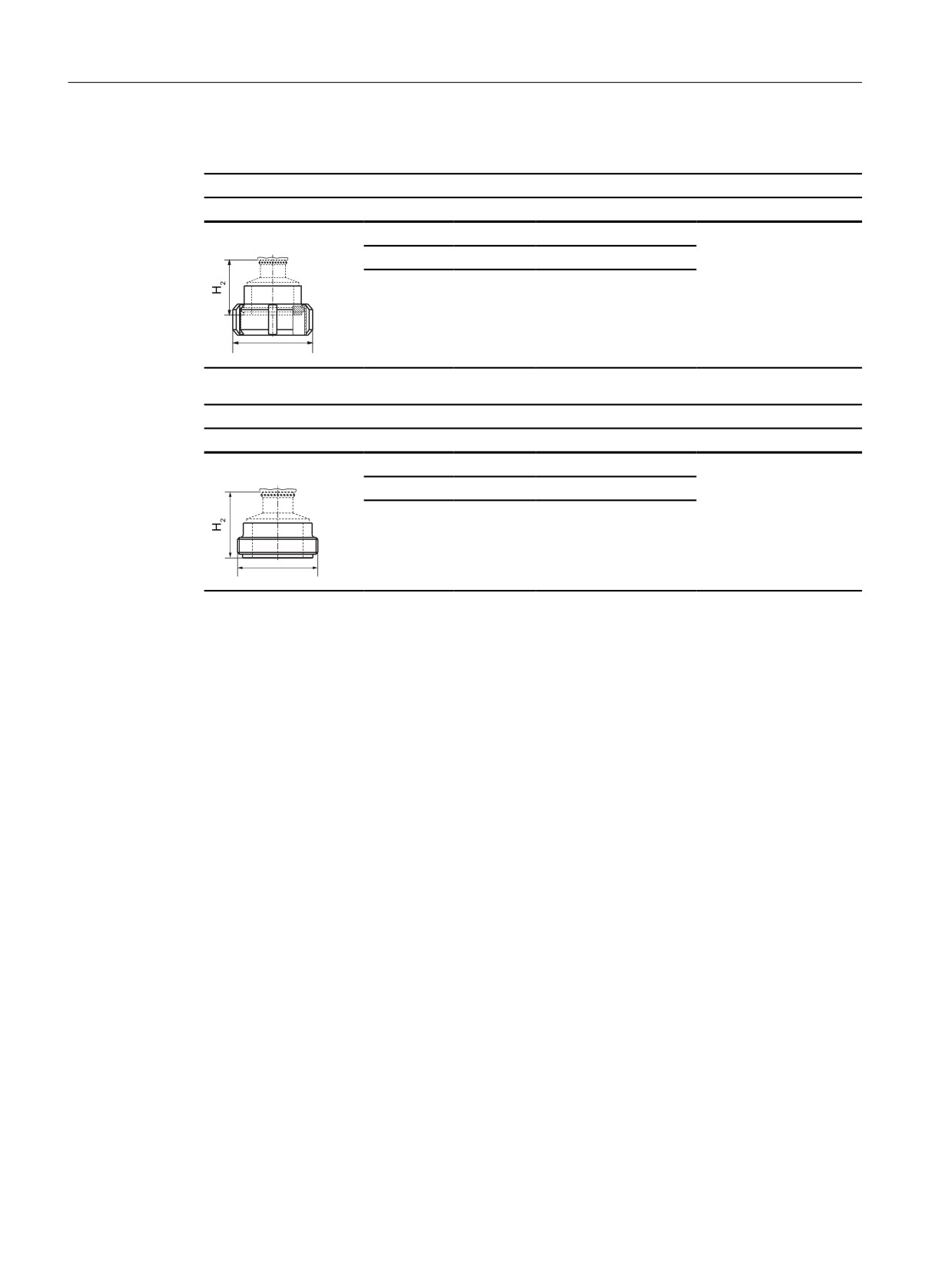
IDF connectors
IDF sockets with union nut
DN
PN
⊘D
H2
2"
25
77 mm (3.0'')
Approx. 52 mm (2.1'')
2½"
25
91 mm (3.6'')
3"
25
106 mm (4.2'')
'
IDF threaded sockets
DN
PN
⊘D
H2
2"
25
64 mm (2.5'')
Approx. 52 mm (2.1'')
2½"
25
77.5 mm (3.1'')
3"
25
91 mm (3.6'')
'
SITRANS P320/P420 with 4 to 20 mA/HART
256
Product documentation and support
A
A.1
Product documentation
Process instrumentation product documentation is available in the following formats:
● Downloads (firmware, EDDs, software) (http://www.siemens.com/processinstrumentation/
downloads)
You have the option to show, open, save, or configure the manual.
- "Display": Open the manual in HTML5 format
- "Configure": Register and configure the documentation specific to your plant
- "Download": Open or save the manual in PDF format
- "Download as html5, only PC": Open or save the manual in the HTML5 view on your PC
You can also find manuals with the Mobile app at Industry Online Support (https://
support.industry.siemens.com/cs/ww/de/sc/2067). Download the app to your mobile device
and scan the device QR code.
Product documentation by serial number
Using the PIA Life Cycle Portal, you can access the serial number-specific product information
including technical specifications, spare parts, calibration data, or factory certificates.
Entering a serial number
2. Select the desired language.
3. Enter the serial number of your device. The product documentation relevant for your device
is displayed and can be downloaded.
To display factory certificates, if available, log in to the PIA Life Cycle Portal using your login or
register.
Scanning a QR code
1. Scan the QR code on your device with a mobile device.
2. Click "PIA Portal".
To display factory certificates, if available, log in to the PIA Life Cycle Portal using your login or
register.
SITRANS P320/P420 with 4 to 20 mA/HART
257
Product documentation and support
A.2 Technical support
A.2
Technical support
Technical support
If this documentation does not completely answer your technical questions, you can enter a
Additional information on our technical support can be found at Technical Support (http://
Service & support on the Internet
In addition to our technical support, Siemens offers comprehensive online services at Service
Contact
If you have further questions about the device, contact your local Siemens representative at
To find the contact for your product, go to "all products and branches" and select "Products &
Services > Industrial automation > Process instrumentation".
Contact address for business unit:
Siemens AG
Digital Industries
Process Automation
Östliche Rheinbrückenstr. 50
76187 Karlsruhe, Germany
SITRANS P320/P420 with 4 to 20 mA/HART
258
Remote operation
B
B.1
SIMATIC PDM
B.1.1
Overview SIMATIC PDM
SIMATIC PDM (Process Device Manager) is a general-purpose, manufacturer-independent
tool for the configuration, parameter assignment, commissioning, diagnostics and
maintenance of intelligent field devices and field components. Follow-up installations and
additional information on SIMATIC PDM are available on the Internet at SIMATIC PDM
SIMATIC PDM monitors the process values, alarms and status signals of the device. It allows
you to display, compare, adjust, verify, and simulate process device data; also to set schedules
for calibration and maintenance.
For information on, for example, how to install and integrate devices, commission the software,
see Operating Manual 'Help for SIMATIC PDM'. The manual is delivered with SIMATIC PDM
software. Once the SIMATIC PDM is installed on your computer you find the manual under:
Start > All programs > Siemens Automation > SIMATIC > Documentation. Link at our website:
SIMATIC PDM instructions and manuals (https://support.industry.siemens.com/cs/ww/en/ps/
16983/man).
Note
Field device parameters
● For a list of parameters and additional information, consult section "Parameter assignment
(Page 101)".
● The field device remains in measurement mode during the time you configure the field
device.
B.1.2
Check SIMATIC PDM version
Procedure
2. Check the support page to make sure you have:
- The latest version of SIMATIC PDM
- The most recent Service Pack (SP)
- The most recent hot fix (HF)
SITRANS P320/P420 with 4 to 20 mA/HART
259

Remote operation
B.1 SIMATIC PDM
B.1.3
Deactivate buffers when connecting via serial modem
Introduction
This deactivation is required to align SIMATIC PDM with the HART modem when using a
Microsoft Windows operating systems.
Deactivating buffers is not necessary when connecting via USB.
Condition
● You connect via RS232 (COM1).
● You have administrative rights on your operating system.
● You know the hardware and software requirements SIMATIC PDM installation
documentation.
Procedure
1. Check the Operating Instructions for SIMATIC PDM for hardware and software
requirements.
2. From the computer desktop, click "Start > Control Panel" to begin configuration.
3. Click "System and Security".
4. Select "Device Manager" under "System".
5. Open folder "Ports".
6. Double click the COM Port used by the system to open the properties window.
7. Select the tab "Port Settings".
8. Click the "Advanced" button.
If the "Use FIFO buffers" radio box is selected, click to deselect.
① Deselect "Use FIFO buffers" radio box
9. Click "OK" button to close out.
10.Close all screens.
11.Restart the computer.
SITRANS P320/P420 with 4 to 20 mA/HART
260
Remote operation
B.1 SIMATIC PDM
B.1.4
Updating the Electronic Device Description (EDD)
Procedure
1. Check that the EDD revision match the Firmware revision in the device according to the
table in section Product compatibility (Page 16).
2. Go to the support page Software downloads (https://www.siemens.com/
processinstrumentation/downloads).
3. Enter the product name in the field "Enter search term...".
4. Download the most current EDD of your device.
5. Save files to your computer in an easily accessed location.
6. Launch SIMATIC PDM - Device Integration Manager.
From the File menu, click "Read device descriptions from compressed source...".
7. Browse to the zipped EDD file, select and open it.
8. Use the "Integration" function to integrate the EDD into the device catalog. The EDD is now
accessible via SIMATIC Manager.
SITRANS P320/P420 with 4 to 20 mA/HART
261
Remote operation
B.1 SIMATIC PDM
SITRANS P320/P420 with 4 to 20 mA/HART
262

Checklist for Functional Safety
C
You can use this checklist to document the steps for enabling Functional Safety.
Step 1: User PIN
Change preset user PIN 2457
● Yes
● Setting range: 1 to 65535
● No
SITRANS P320/P420 with 4 to 20 mA/HART
263

Checklist for Functional Safety
Step 2: Validate values using the "Func-
Values for the validation
Enter validated value
tional Safety" wizard
①
Device identification data (if Function-
The values can be found on the
al Safety is enabled via remote oper-
nameplate of the device and are
ation)
displayed via the wizard.
● Long tag
● Product name
● Serial number
②
Safety-related parameters
S1
Primary variable
Pressure (the parameter cannot be
changed)
S2
Damping value
0.01 s ... 100 s in increments of
0.01 s
S3
Lower range value
The value is within the measuring
limits. You can find information on
the nameplate of the device or in
the section Technical data
(Page 199)
S4
Upper range value
The value is within the measuring
limits. You can find information on
the nameplate of the device or in
the section Technical data
(Page 199)
S5
Application
● Linear, proportional to pressure
(PRESS).
● Linear, proportional to level
(LEVEL).
● Proportional to flow rate, two-
step linear up to the application
point (VSLN2 or MSLN2).
S6
Overload behavior
Alarm or warning
S7
Upper saturation limit
Between 20 mA and the upper fault
current
③
Fingerprint (only if Functional Securi-
The value is displayed using the
ty is enabled via remote operation)
"Functional Safety" wizard.
Step 3: Safety function
Validate the safety function using the "Functional Safety" wizard
● Yes
● No
Enter the date of validation of the safety function
SITRANS P320/P420 with 4 to 20 mA/HART
264
Checklist for Functional Safety
Date when Functional Safety was enabled
Signature
SITRANS P320/P420 with 4 to 20 mA/HART
265
Checklist for Functional Safety
SITRANS P320/P420 with 4 to 20 mA/HART
266

Sealing plug / thread adapter
D
D.1
Intended use of accessory part
The sealing plug and the thread adapter (components) can be used for installation in electrical
equipment of flameproof" "Ex d" type of protection of groups IIA, IIB, IIC as well as dust
protection by enclosure "Ex t" type of protection.
D.2
Safety instructions for accessory part
WARNING
Incorrect assembly
● The component can be damaged or destroyed or its functionality impaired through
incorrect assembly.
- Mount the component using a suitable tool. Refer to the information in Chapter
"Technical specifications of accessory part (Page 268)", for example, torques for
installation.
● For "Explosion-proof Ex d" type of protection: To ensure an engagement depth of 8 mm,
the enclosure must have a wall thickness of at least 10 mm.
Improper modifications
Danger to personnel, system and environment can result from modifications and repairs of the
component, particularly in hazardous areas.
● Any modification which deviates from the delivery state is not permitted.
Loss of enclosure type of protection
IP protection is not guaranteed without sealant.
● Use a suitable thread sealant.
● If you are using the component in type of protection dust protection by enclosure "Ex t", use
the supplied sealing ring (①, figure in Chapter "Dimensional drawings for accessory part
(Page 269)").
Unsuitable fluids in the environment
Danger of injury or damage to device.
Aggressive media in the environment can damage the sealing ring. Type of protection and
device protection may no longer be guaranteed.
● Make sure that the sealing material is suitable for the area of use.
SITRANS P320/P420 with 4 to 20 mA/HART
267

Sealing plug / thread adapter
D.3 Technical specifications of accessory part
Note
Loss of type of protection
Changes in the ambient conditions can loosen the component.
● As part of the recommended maintenance intervals: Check the compression fitting for tight
fit and tighten, if necessary.
D.3
Technical specifications of accessory part
Technical specifications sealing plug and thread adapter
Sealing plug suitable for types of protection
Explosion-proof enclosure "d" of groups IIA, IIB, IIC
Dust protection by enclosure "t"
Standard compliance
The components meet Directive 94/9. They meet the requirements of
standards IEC/EN 60079-0; IEC/EN 60079-1; IEC/EN 60079-31.
Explosion protection
● Gas explosion protection
II2G Ex d IIC
● Dust explosion protection
II1D Ex t IIIC
Certificates
IECEx TUN 13.0022 U
TÜV 13 ATEX 121710 U
Material for sealing plug / thread adapter
Stainless steel
Material for seal
Vulcanized fiber or Victor Reinz AFM 30
Ambient temperature range
-40 ... +100 °C (-40 ... +212 °F)
For "Ex d" type of protection:
Required wall thickness for tappings
10 mm
Torque
● For thread size M20 x 1.5
65 Nm
● For thread size M25 x 1.5
95 Nm
● For thread size ½-14 NPT
65 Nm
Width A/F for thread size M20 x 1.5
27
Width A/F for thread size M25 x 1.5
30
Key size for thread size ½-14 NPT
10
SITRANS P320/P420 with 4 to 20 mA/HART
268
Sealing plug / thread adapter
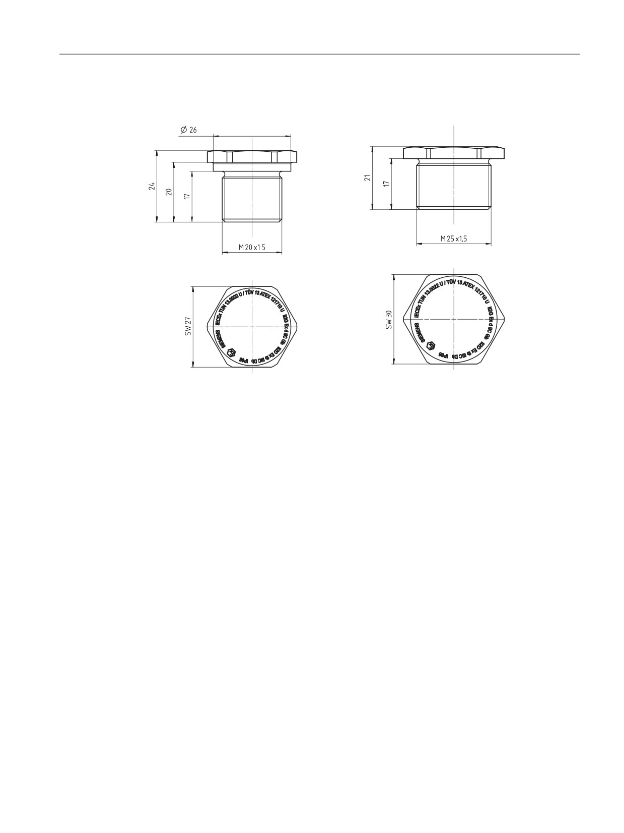
D.4 Dimensional drawings for accessory part
D.4
Dimensional drawings for accessory part
Sealing plug Ex d, M25 x 1.5, dimensions in mm
Sealing plug Ex d, M20 x 1.5, dimensions in mm
SITRANS P320/P420 with 4 to 20 mA/HART
269
Sealing plug / thread adapter
D.4 Dimensional drawings for accessory part
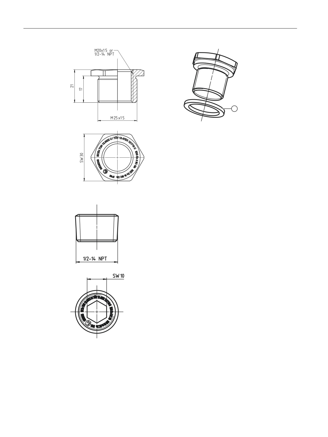
① Sealing ring: Use for dust protection "Ex t" type
of protection.
Thread adapter Ex d, M25 x 1.5 on M20 x 1.5 and
M25 x 1.5 on ½-14 NPT, dimensions in mm
Sealing plug Ex d ½ -14 NPT
SITRANS P320/P420 with 4 to 20 mA/HART
270

Abbreviations
E
Abbreviation
In full
Meaning
PED
Pressure Equipment Directive
HART
Highway Addressable Remote Transducer
Standardized protocol for transmission of information between field
device and automation system.
LRL
Lower Range Limit
Lower end of the measuring range
LRV
Lower Range Value
Lower end of the set measuring span
MA
Lower range value
Lower end of the set measuring span
ME
Upper range value
Upper end of the set measuring span
MAWP
Maximum Allowable Working Pressure (PS)
Maximum permissible operating pressure
NFPA
National Fire Protection Association
US - American Fire Protection Organization
F&B
Food and beverage industry
PDM
Process Device Manager
Tool for communication with HART devices (manufacturer: Siemens)
r
Turn-down
Ratio of the set measuring span to the maximum set measuring span,
for example
S >EDU@
7XUQ GRZQ
Set measuring span: 0.4 bar
Maximum configured measuring span: 1 bar
URL
Upper Range Limit
Upper end of the measuring range
URV
Upper Range Value
Upper end of the set measuring span
SITRANS P320/P420 with 4 to 20 mA/HART
271
Abbreviations
SITRANS P320/P420 with 4 to 20 mA/HART
272
Glossary
ATEX
ATEX is an abbreviation of the French term "Atmosphère explosible" (potentially explosive
atmosphere). ATEX stands for both EC directives in the area of explosion protection: ATEX
product directive 94/9/EC and ATEX operating directive 1999/92/EC.
Auxiliary power supply
Auxiliary power supply refers to an electrical supply or reference voltage which some electrical
circuits require apart from the standard supply. The auxiliary power supply can, for example, be
specially stabilized, have a particular level or polarity and/or other properties which are
important for the correct functioning of switch components.
Auxiliary voltage
→ Auxiliary power supply
Dangerous failure
Failure with the potential to switch a safety-instrumented system to a hazardous or non-
functioning safety state.
EEPROM
EEPROM (Electrically Erasable Programmable Read-Only Memory): a non-volatile, electronic
memory module.
EEPROMs are often used where individual bytes of data (e.g. configuration data or runtime
meters) change over time and must be stored safely in the event of a mains power failure.
Failure/Fault/Error
Failure:
A resource is no longer capable of executing a required function.
Fault/Error:
Undesired state of a resource indicated by its incapability of executing a required function.
Fault/Error
→ Failure/Fault/Error
Final controlling element
Converter that converts electrical signals into mechanical or other non-electric variables.
SITRANS P320/P420 with 4 to 20 mA/HART
273
Glossary
Fingerprint
Numerical value generated by the device when you start safety validation via the "Functional
Safety" wizard. By comparing the fingerprint, you determine whether or not the device and the
safety-related parameters have changed erroneously during activation of the functional safety.
Firmware
Firmware (FW) is software that is embedded on a chip in electronic devices - in contrast to
software which is saved on hard disks, CD-ROMs or other media. These days, firmware is
mostly stored in a flash memory or EEPROM.
Firmware usually contains the elementary functions for controlling the device, as well as input
and output routines.
Frequency shift keying
Frequency shift keying is a simple form of modulation, where the digital values 0 and 1
modulate the actual current signal by means of two different frequencies.
Frequency Shift Keying (FSK)
→ Frequency shift keying
HART
HART (Highway Addressable Remote Transducer) is a standardized, widely used
communications system used to structure industrial fieldbusses. The communications system
provides digital communications for multiple participants (field devices) via a common databus.
HART is based especially on the equally widely used 4/20 mA standard for the transfer of
analog sensor signals. The cabling from existing older systems can be used directly and both
systems operated in parallel.
HART specifies several protocol levels in the OSI model. It facilitates the transfer of process
and diagnostics data and control signals between field devices and high-level control systems.
Standardized parameter sets can be used for the manufacture-independent operation of all
HART devices.
Typical applications include transmitters for measuring mechanical and electrical dimensions.
Non-volatile memory
→ EEPROM
r
→ Spread
Risk
Combination of the probability of damage occurring and the extent of the damage.
SITRANS P320/P420 with 4 to 20 mA/HART
274
Glossary
Safety function
Defined function executed by a safety-instrumented system with the objective of attaining or
maintaining a safe system state by taking a defined hazardous incident into account.
Example:
Limit pressure monitoring
Safety Integrity Level
→ SIL
Safety-instrumented system
A safety-instrumented system (SIS) executes the safety functions that are required to achieve
or maintain a safe state in a system. It consists of a sensor, logic unit/control system and final
controlling element.
Example:
A safety-instrumented system is made up of a pressure transmitter, a limit signal sensor and a
control valve.
Sensor
Converter that converts mechanical or other non-electric variables into electrical signals.
SIL
The international standard IEC 61508 defines four discrete safety integrity levels (SIL) from SIL
1 to SIL 4. Each level corresponds to a probability range for the failure of a safety function. The
higher the SIL of the safety-instrumented system, the higher the probability that the required
safety function will work.
The SIL which can be achieved is determined by the following safety-instrumented
characteristics:
● Average probability of failure on demand (PFDAVG)
● Hardware fault tolerance (HFT)
● Safe failure fraction (SFF)
Spread
Ratio of the set measuring span to the maximum set measuring span.
Total error
Total Error is sum of Total Performance and the long-term stability.
SITRANS P320/P420 with 4 to 20 mA/HART
275
Glossary
Total Error(s)
→ Total error
Total Performance
Total Performance is the square root of the sum of the squares of the three deviations resulting
from the influence of the static pressure, the temperature and the characteristic deviation.
TP
→ Total Performance
SITRANS P320/P420 with 4 to 20 mA/HART
276
Index
DEVICE MODE, 79
Device plug
3
Installing, 61
Diagnostic messages, 192
3A, 249
Differential pressure, 25, 26
Direct sunlight, 46
Disassembly, 64
A
Display
ACCES
Symbols, 81
INVALID CFG, 197
DISPLAY TEST, 79
Ambient temperature, 228, 229, 230, 232
Disposal, 188
Effect, 212, 222
Document history, 15
APPLICATION, 78, (Transfer function)
Downloads, 257
APPLY LRV, 79
APPLY URV, 79
Approval
E
3A, 249
Edit view, 80
EHEDG, 249
EHEDG, 249
Electromagnetic compatibility, 229, 230, 231, 232
EMC, 229, 230, 231, 232
B
ETEMP, 127
Bidirectional flow measurement, 116
Blowout valve, 92
Blowout valves, 95
F
Bridge output voltage, 33, 37, 38
FAULT CURR, 79
BUTTON LOCK, 79
Filling liquid, 33, 36, 38
Fingerprint, 171
Flange, 51
C
FLAT, 112
Cable gland
FUNCT SAFETY, 79
Installing, 61
Function chart, 34
Catalog
catalog sheets, 257
Certificates, 19, 257
H
CHANGE PIN, 79
HALF, 112
Cleaning, 182
HART
CONIC, 112
Modem, 39
Current simulator trim, (See DAC trim)
Hazardous area
CUSTM, 112
Laws and directives, 19
Customer Support, (Refer to Technical support)
Qualified personnel, 21
CYLIN, 112
Hotline, (Refer to Support request)
HW exchange counter, 104
Hygienic version
D
Install, 50
DAC trim, 152
DAMPING, 78
Declaration of conformity for functional safety, (See
SIL declaration of conformity)
SITRANS P320/P420 with 4 to 20 mA/HART
277
Index
Mounting flange, 38
MSL2B, 112
I
MSLN, 112
MSLN2, 112
Identification data
MSOFF, 112
define, 146
multi-channel operation, 161
IDENTIFY, 79
MWP, (See MAWP)
In accordance with the square root function
see square-root extraction, 115
Install
N
Remote seal, 54
Installation, 47
Nameplate, 28
Insulation, 49
O
L
Order supplement, 28
Laws and directives
OVERLD BEHAV, 79
Disassembly, 19
Personell, 19
Layout of nameplate with general information, 28
P
LEVEL, 112, 127
PARAB, 112
LEVEL UNITS, 79
PARAE, 112
LO FAULT CUR, 79
PARAM
Load, 228
INVALID CFG, 197
LOOP TEST, 79
Parameter
LOOPT
Parameter list, 101
INVALID CFG, 197
Parameter view, 78
LOW FLOW CUT, 79
PIN RECOVERY, 79
Low flow cut-off, 115, 132
Position error compensation, 120
LOWER RANGE, 78
PRESS, 112
LOWER SCALNG, 79
PRESS UNITS, 78
PRESSURE REF, 79
Pressure reference, 106
M
Pressure units, 106
Main entry, 40
Maintenance, 181
Manuals, 257
Q
MAWP, 271
QR code, 28
Measurement view, 76
Qualified personnel, 21
Measuring cell
Quick start, 101
Absolute pressure, 34
Differential pressure and flow, 37
Gauge pressure, 33
R
Level, 38
Measuring point, 29
RECOVERY ID, 79
MFLOW, 127
Remote seal
MFLOW UNITS, 79
Install, 54
Modifications
Maintenance, 182
correct usage, 20
RESET, 79
improper, 20
Return procedure, 188
Mounting bracket
Install, 49
SITRANS P320/P420 with 4 to 20 mA/HART
278
Index
Threaded adapter
Technical specifications, 268
S
Torque, 268
Torques, 238
Safety characteristic values, 162
Transfer function, (See Application)
Safety function, 160
TRNFK
Safety-related parameters, 165
INVALID CFG, 197
SATURAT HIGH, 79
Turn-down, 271
SATURAT LOW, 79
Scope of delivery, 16
Sealing plug
U
Technical specifications, 268
Sealing plugs
UP FAULT CUR, 79
Installing, 61
UPPER RANGE, 78
Sensor calibration, 151
UPPER SCALNG, 79
Serial number, 30
Useful lifetime, 162
Service, 258
USER, 127
Service and support
USER PIN, 79
Internet, 258
Factory setting,
Shut-off valve, 94, 97, 99
SIL 2
Single-channel operation, 161
V
SIL 3, 161
Vent valve, 97, 99
SIL declaration of conformity, 162
VESSEL DIM A, 79
SIMUL
VESSEL DIM L, 79
INVALID CFG, 197
VFLOW, 127
SPHER, 112
VFLOW UNITS, 79
Spread, (See Turn-down)
VLIN, 112
SQRT POINT, 79
VOL, 127
Square root function
VOL UNITS, 79
Hold at 0, square root, 115
VSL2B, 112
Linear, square root, 115
VSLN, 112
Two step linear, square root, 116
VSLN2, 112
Stabilizing valve, 95, 97, 99
VSOFF, 112
START VIEW, 79
Structure, 27
STSIM
W
INVALID CFG, 197
Support, 258
Warranty, 17
Support request, 258
Write protection, 82
SV SELECT, 79
Jumper, 82
T
Z
Tank connection, 255
ZERO POINT, 79
Technical support, 258
Zero point adjustment, 120
partner, 258
Zero point calibration
personal contact, 258
See Zero point adjustment, 120
TEMP, 127
Zero point error, 120
TEMP UNITS, 79
Test certificates, 19
SITRANS P320/P420 with 4 to 20 mA/HART
279