Siemens SITRANS P. Operating Instructions (2019) - page 8
Index
SITRANS P320/P420 with 4 to 20 mA/HART
280

SITRANS P
measuring instruments
for pressure
2/2
Product overview
2/150
Remote seals for transmitters and
pressure gages
2/4
Transmitters for gage, absolute and
2/150
Technical description
differential pressure
2/158
Diaphragm seals of sandwich design
2/4
Z series for gage pressure
2/161
Diaphragm seals of flange design
2/6
Z series for gage and absolute pressure
2/170
Quick-release diaphragm seals
2/12
SITRANS P250 for differential pressure
2/173
Miniature diaphragm seal
2/17
ZD series for gage and absolute pressure
2/174
Flushing rings
2/176
Clamp-on seals of flange design
2/21
Transmitters for food, pharma-
2/179
Quick-release clamp-on seals
ceuticals and biotechnology
2/182
Remote seals - Measuring setups
2/21
SITRANS P Compact for gage
2/187
Questionnaire
and absolute pressure
2/28
SITRANS P300 for gage and absolute
2/190
Fittings
pressure
2/190
Technical description
2/191
Selection aid
2/47
Transmitters for gage pressure for pa-
Shut-off valves for gage and absolute
per industry
pressure transmitters
SITRANS P300 and DS III series with
2/193
Shut-off valves to DIN 16270, DIN 16271
PMC connection
and DIN 16272
2/47
Technical description
2/195
Angle adapter
Technical specifications, ordering data,
2/196
Double shut-off valves
dimensional drawings
2/52
- DS III series with PMC connection
2/197
Accessories for shut-off
valves/double shut-off valves
2/58
- SITRANS P300 with PMC connection
2/198
2-way valve manifolds DN 5
2/63
Transmitters for gage, absolute and
Shut-off valves for differential pressure
differential pressure, flow and level
transmitters
DS III, DS III PA and DS III FF series
2/201
2-, 3- and 5-spindle valve manifolds DN 5
2/63
Technical description
2/204
Multiway cocks PN 100
Technical specifications, ordering data,
2/206
3-way and 5-way valve manifolds DN 5
dimensional drawings
2/209
3-way valve manifold DN 8
2/70
- for gage pressure
2/212
Valve manifold combination DN 5/DN 8
2/79
- for gage and absolute pressure with
2/214
Valve manifold combination DN 8
front-flush diaphragm
2/216
2-, 3- and 5-spindle valve manifolds for
2/89
- for absolute pressure (from gage
installing in protective boxes
pressure series)
2/220
3- and 5-spindle valve manifolds for
2/98
- for absolute pressure
vertical angular diff. pressure lines
(from differential pressure series)
2/223
Low-pressure multiway cock
2/107
- for differential pressure and flow
Accessories
2/124
- for level
2/225
Oval flange
2/226
Adapters, connection glands
2/134
SITRANS P Accessories
2/227
Connection parts G½
2/134
Supplementary electronics for 4-wire con-
2/228
Water traps, Sealing rings to EN 837-1
nection
2/229
Pressure surge reducers
2/136
Accessories/spare parts for SITRANS P,
2/230
Primary shut-off valves
P300 and DS III series
2/232
Compensation vessels
2/142
Factory-mounting of valve manifolds on
2/233
Connection parts
SITRANS P transmitters
2/146
Transmitters for hydrostatic level
2/146
MPS series (submersible sensor)
You can download all instructions, cata-
logs and certificates for SITRANS P free
of charge at the following Internet ad-
dress:

SITRANS P measuring instruments for pressure
Product overview
■Overview
Application
Description
Page
Software for
Parameterization
SITRANS P - measuring instruments for pressure, absolute pressure, differential pressure, flow and level
Two- or three-wire transmitters
SITRANS P, Z series
2/4
-
2
for measuring gage and abso-
Compact single-range transmitters
lute pressure
Analog electronics
Available ex stock
Two- or three-wire transmitters
SITRANS P250
2/12
-
for measuring differential pres-
Compact single-range transmitters
sure
Analog electronics
Available ex stock
Two- or three-wire transmitters
SITRANS P, ZD series
2/17
-
for measuring gage and abso-
Range adjustment: 5 : 1
lute pressure
Digital display
Available ex stock
Transmitters for gage and abso-
SITRANS P Compact
2/21
-
lute pressure for food, pharma-
Single-range transmitters in 2-wire system
ceuticals and biotechnology
Hygiene-based design with various aseptic connec-
tions according to EHEDG, FDA and GMP recom-
mendations.
Two-wire transmitters for mea-
SITRANS P300
2/28
SIMATIC PDM
suring gage and absolute pres-
• Hygiene-based design according to EHEDG, FDA
sure
and GMP
• Parameterization over 3 buttons or communication
over HART, PROFIBUS PA or FOUNDATION
Fieldbus
• Standard process connection G½, ½-NPT and
flush-mounted process connections available
• Measuring range adjustment 100 : 1
Two-wire transmitters for mea-
SITRANS P300 and DS III series with PMC con-
2/47
SIMATIC PDM
suring gage pressure
nection for the paper industry
• Measuring range adjustment 100 : 1
• Process connections for the paper industry
• Parameter assignment over 3 buttons and HART,
PROFIBUS PA or FOUNDATION Fieldbus
Two-wire transmitters for mea-
SITRANS P, DS III series
2/63
SIMATIC PDM
suring:
SITRANS P, DS III PA series
SIMATIC PDM
• Gage pressure,
SITRANS P, DS III FF series
• Absolute pressure
Range adjustment: 100 : 1
• Differential pressure and
Parameterization using:
• Flow or
• 3 keys and HART for DS III series
• Level
• 3 keys and PROFIBUS-PA for DS III PA series
• 3 buttons and FOUNDATION Fieldbus for DS III FF
series
• Available ex stock
Supplementary electronics for
Output: 0 or 4 to 20 mA
2/134
-
adaptation of two-wire transmit-
Power supply: 24 V AC/DC, 230 V AC
ters for four-wire connections
2/2

SITRANS P measuring instruments for pressure
Product overview
Application
Description
Page Software for
Parameterization
2-wire transmitter for measuing SITRANS P, MPS series (submersible sensor)
2/146
-
hydrostatic levels
For measuring liquid levels in wells, tanks, channels,
dams etc.
2
Remote seals for measuring
Remote seals in sandwich and flange designs
2/150
-
viscous, corrosive or fibrous
Quick-release remote seals for the food industry
media (as well as media at
extreme temperatures)
Wide range of diaphragm materials and filling liq-
uids available
Shutting off the lines for the
Shut-off fittings and valve manifolds available in
2/190
-
medium and differential pres-
steel, brass or stainless steel
sure
Valve manifolds available for the various process
Mounting of transmitter on valve
connections of the SITRANS P transmitters
manifold or shut-off fitting
2/3

SITRANS P measuring instruments for pressure
Transmitters for gage, absolute and differential pressure
Z series for gage pressure
■Overview
■Design
The main components of the pressure transmitter are:
• Brass housing with silicon measuring cell and electronics
plate
• Process connection
2
• Electrical connection
The silicon measuring cell has a thin-film strain gage which is
mounted on a ceramic diaphragm. The ceramic diaphragm can
also be used for aggressive media.
The process connection to DIN EN 837-1 is made of brass and
has a male thread G½B or a female thread G1/8B.
The electrical connection is made using a plug to DIN 43650
with a M16x1.5 cable inlet.
■Function
The pressure transmitters of the Z series for gage pressure mea-
sure the pressure of aggressive and non-aggressive gases,
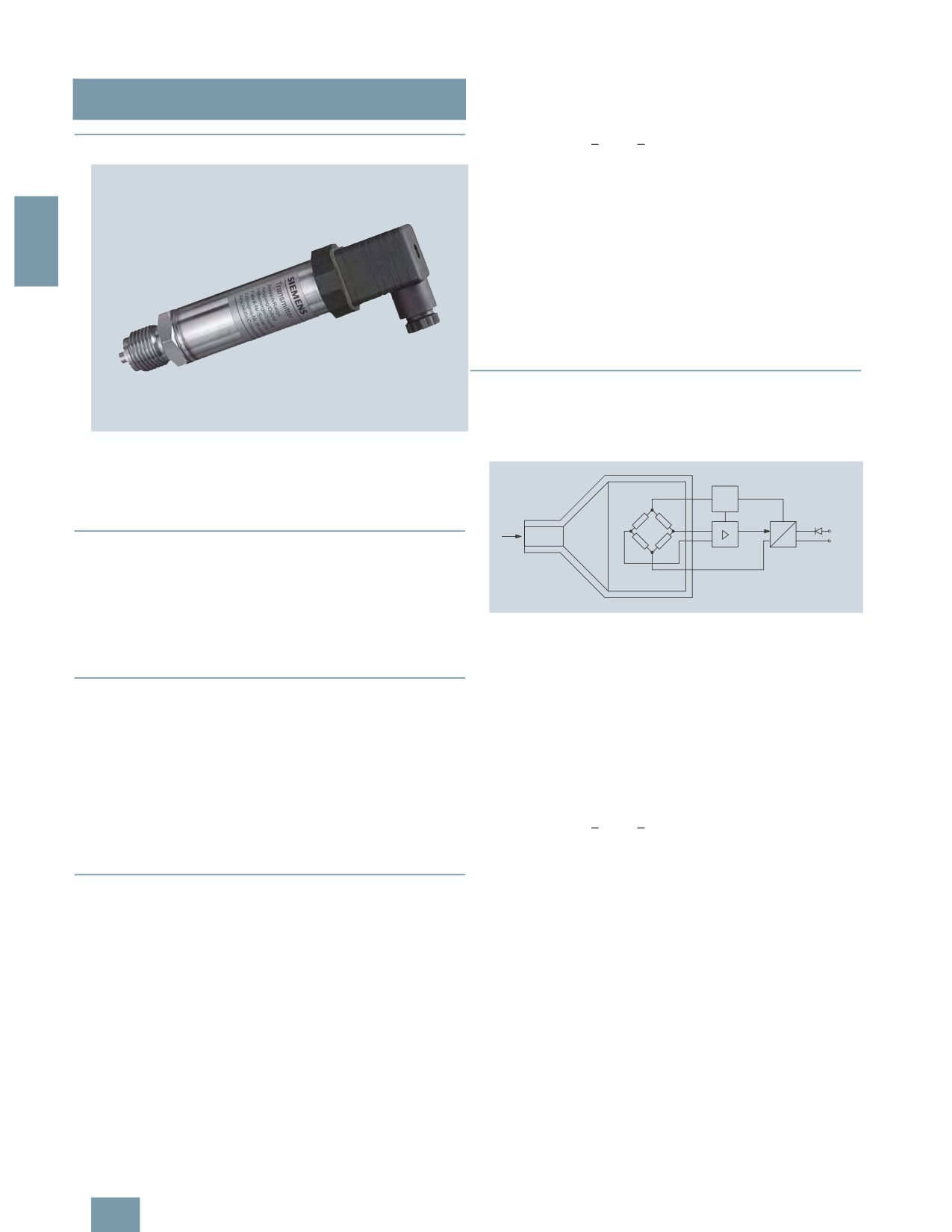
SITRANS P pressure transmitters, Z series for gage pressure
liquids and vapors.
(7MF1562-...)
The measuring cell is temperature-compensated.
The SITRANS P pressure transmitter, Z series (7MF1562-...),
Mode of operation
measures the gage pressure of aggressive and non-aggressive
gases, liquids and vapors.
■ Benefits
• High measuring accuracy
• Sturdy brass housing
• For aggressive and non-aggressive media
• For measuring the pressure of liquids, gases and vapor
• Temperature-compensated measuring cell
• Compact design
SITRANS P pressure transmitters, Z series (7MF1562-...), functional dia-
■Application
gram
The pressure transmitter of the Z series for gage pressure
The thin-film measuring cell has a thin-film resistance bridge at
(7MF1562-...) is used above all in the following industrial areas:
which the operating pressure p is transmitted through a ceramic
diaphragm.
• Power engineering
• Mechanical engineering
The measuring cell output voltage is fed to an amplifier and con-
verted into an output current of 4 to 20 mA. The output current
• Shipbuilding
is linearly proportional to the input pressure.
• Water supply etc.
A concrete application example is the measurement of com-
pressed air containing oil in compressors or compressor sta-
tions.
2/4

SITRANS P measuring instruments for pressure
Transmitters for gage, absolute and differential pressure
Z series for gage pressure
Design
■ Technical specifications
Weight
≈ 0.2 kg (≈ 0.44 lb)
SITRANS P pressure transmitter, Z series for gage pressure
Wetted parts materials
Mode of operation
• Measuring cell
Al2O3 - 96%
Measuring principle
Thin-film strain gage
• Process connection
Brass, mat. No. 2.0402
Input
2
• Gasket
Viton
Measured variable
Realtive pressure
Process connection
Male thread G½B
Measured range
0 to 16 bar g (0 to 232 psi g) or
female thread G1/8B
0 to 25 bar g (0 to 363 psi g)
Power supply
Output
Terminal voltage on pressure trans-
Current output signal
4 ... 20 mA
mitter
Measuring accuracy
To EN 60770-1
• For current output
10 to 36 V DC
Error in measurement (at 25 °C
0.5% of full-scale value-typical
Certificate and approvals
(77 °F), including conformity error,
Classification according to pressure
For gases of fluid group 1 and
hysteresis and repeatability)
equipment directive
liquids of fluid 1; complies with
Response time T99
< 0.1 s
(DRGL 97/23/EC)
requirements of article 3, para-
graph 3 (sound engineering prac-
Long-term drift
tice)
• Start of scale
0.3% of full-scale value/year - typ-
ical
• Measured span
0.3% of full-scale value/year - typ-
ical
■Dimensional drawings
Influence of ambient temperature
• Start of scale
0.3%/10 K (0.3%/10 K) of full-
scale value - typical
• Measured span
0.3%/10 K (0.3%/10 K) of full-
scale value - typical
Rated conditions
Medium conditions
• Process temperature
-30 ... +120 °C (-22 ... +248 °F)
6:
0
[
Degree of protection to EN 60529
IP65
Ambient conditions
SITRANS P pressure transmitters, Z series (7MF1562-...), dimensions in
• Ambient temperature
-25 ... 85 °C (-13 ... +185 °F)
mm (inch)
• Storage temperature
-50 ... 100 °C (-58 ... +212 °F)
■Schematics
!
"
#
$
%
$
%
SITRANS P pressure transmitters, Z series (7MF1562-...), connection dia-
gram
Order No.
Order code
■Selection and Ordering data
SITRANS P pressure transmitters, Z series for pressure
D) 7 M F 1 5 6 2 - 7 7 7 0 0
7
7
7
2-wire system, characteristic rising
Measured range
Max. working pressure
0 ... 16 bar g
(0 ... 232 psi g)
32 bar g
(464 psi g)
3
C
B
0 ... 25 bar g
(0 ... 363 psi g)
64 bar g
(928 psi g)
3
C
D
Other version for measuring range ≥ 1 bar g (≥ 14.5 psi g), add Order code and plain text:
9
A
A
H
1
Y
Measuring range: ... to ... bar g (psi g)
D) Subject to export regulations AL: N, ECCN: EAR99H.
2/5
SITRANS P measuring instruments for pressure
Transmitters for gage, absolute and differential pressure
Z series for gage and absolute pressure
Measuring range ≥1 bar (≥14.5 psi)
■Overview
Main components:
• Stainless steel housing with ceramic measuring cell and elec-
tronics module. The temperature-compensated ceramic mea-
suring cell has a thin-film strain gage which is mounted on a
ceramic diaphragm. The ceramic diaphragm can also be
2
used for aggressive media.
• Process connection made of stainless steel in diverse designs
(see Selection and Ordering data)
• Electrical connection made using a plug to DIN 43650 with the
cable inlet M16 x 1.5, ½-14 NPT or round plug connector M12.
The pressure transmitters with a nominal range ≥ 1 bar g
(≥ 14.5 psi g) are optionally available with or without explosion
protection.
■Function
The pressure transmitter measures the gage and absolute pres-
sure as well as the level of liquids and gases.
Mode of operation
SITRANS P pressure transmitters, Z series for pressure and absolute
pressure (7MF1564-...)
SITRANS P pressure transmitters, Z series (7MF1564-...), mea-
sure the gage and absolute pressure as well as the level of liq-
uids and gases.
■ Benefits
• High measuring accuracy
• Sturdy stainless steel housing
• For aggressive and non-aggressive media
• For measuring the pressure of liquids, gases and vapor
SITRANS P pressure transmitters, Z series (7MF1564-...), functional dia-
• Temperature-compensated measuring cell
gram
• Compact design
The mode of operation of the pressure transmitter is dependent
on the measuring range.
■Application
Measuring range <1 bar (<14.5 psi)
The pressure transmitter of the Z series for gage pressure and
The silicon measuring cell of the pressure transmitter has a
absolute pressure (7MF1564-...) is used above all in the follow-
piezo-resistive bridge to which the operating pressure is trans-
ing industrial areas:
mitted through silicone oil and a stainless steel diaphragm.
• Chemical industry
The measuring cell output voltage is fed to an amplifier and con-
• Pharmaceutical industry
verted into an output current 4 ... 20 mA. The output current is
• Food industry
linearly proportional to the input pressure
• Mechanical engineering
Measuring range ≥1 bar (≥14.5 psi)
• Shipbuilding
The thin-film measuring cell has a thin-film resistance bridge to
• Water supply
which the operating pressure p is transmitted through a ceramic
diaphragm.
■Design
The voltage output from the measuring cell is converted by an
The design of the pressure transmitter is dependent on the mea-
amplifier into an output current 4 ... 20 mA or an output voltage
suring range.
of 0 ... 10 V DC.
Measuring range <1 bar (<14.5 psi)
The output current and voltage are linearly proportional to the in-
put pressure
Main components:
• Stainless steel housing with piezo-resistive silicon measuring
cell (with stainless steel diaphragm, temperature-compen-
sated) and electronics module
• Process connection made of stainless steel in diverse designs
(see Selection and Ordering data)
• Electrical connection made using a plug to DIN 43650 with the
cable inlet M16 x 1.5, ½-14 NPT or round plug connector M12.
The pressure transmitters with a nominal range < 1 bar g
(< 14.5 psi g) are optionally available with or without explosion
protection.
2/6

SITRANS P measuring instruments for pressure
Transmitters for gage, absolute and differential pressure
Z series for gage and absolute pressure
Power supply UH
■ Technical specifications
Terminal voltage on pressure trans-
SITRANS P pressure transmitters, Z series for gage pressure, abso-
mitter
lute pressure and level
• For current output
10 ... 36 V DC
Mode of operation
• For voltage output signal (only
15 ... 36 V DC
• Measuring range <1 bar
Piezo-resistive
measuring range ≥ 1 bar
(<14.5 psi)
2
(14.5 psi))
• Measuring range ≥1 bar
Thin-film strain gage
Certificate and approvals
(≥14.5 psi)
Classification according to pressure
For gases of fluid group 1 and liq-
Input
equipment directive
uids of fluid 1; complies with
Measured variable
Gage and absolute pressure
(DRGL 97/23/EC)
requirements of article 3, para-
graph 3 (sound engineering prac-
Measured range
tice)
• Pressure
Explosion protection
- Metric
0 ... 400 bar g (0 ... 5802 psi g)
• Intrinsic safety "i" (only with current TÜV 02 ATEX 1953X
output)
- US measuring range
0 ... 6000 psi g
- Identification
Ex II 1/2G EEx ia IIC T4
• Absolute pressure
• Intrinsic safety "T.I.I.S." (only with
applied
- Metric
0 ... 16 bar a (0 ... 232 psi a)
current output)
- US measuring range
0 ... 300 psi a
Lloyds Register of Shipping
Certificate No. 03/30003
Output
Output signal
• Current output signal
4 ... 20 mA
■Dimensional drawings
• Voltage output signal (only mea-
0 ... 10 V DC
suring range ≥ 1 bar (14.5 psi))
132 (5.2) without Ex protection1)
Accuracy
To EN 60770-1
5
20
141 (5.6) with Ex protection
Error in measurement (at 25 °C
0.25% of full-scale value - typical
(0.2)
(0.8)
(77 °F), including conformity error,
hysteresis and repeatability)
Response time T99
< 0.1 s
Long-term drift
• Start of scale
0.25% of full scale value/year
• Full-scale value
0.25% of full scale value/year
Influence of ambient temperature
SW27
1) Length on version for voltage
M16x1,5
• Start of scale
0.25%/10 K (0.25%/10 K) of full-
output 0 ... 10 V: 106 (4.2)
or
scale value
2) Inner diameter 3 (0.12)
½-14 NPT
• Full-scale value
0.25%/10 K (0.25%/10 K) of full-
scale value
Pressure transmitter 7MF1564-... with process connection G½" male,
dimensions in mm (inch)
Rated operating conditions
Process temperature
-30 ... +120 °C
(-22 … +248 °F)
122 (4.8) without Ex protection1)
131 (5.15) with Ex protection
Ambient temperature
-25 ... +85 °C (-13 … +185 °F)
16
(0.63)
Storage temperature
-50 ... +100 °C
(-58 … +212 °F)
Degree of protection to EN 60529
IP65
Design
Weight
≈ 0.25 kg (≈ 0.55 lb)
Wetted parts materials
• Measuring cell
SW27
1) Length on version for voltage
M16x1,5
- Measuring range <1 bar
Stainless steel, 1.4571/316Ti
or
output 0 ... 10 V: 96 (3.8)
(<14.5 psi)
½-14 NPT
2) Inner diameter 3 (0.12)
- Measuring range ≥1 bar
Al2O3 - 96%
(≥14.5 psi)
Pressure transmitter 7MF1564-... with process connection G¼" male,
dimensions in mm (inch)
• Process connection
Stainless steel, mat. No.
1.4571/316Ti
• Gasket
Viton
Process connection
See Selection and Ordering data
2/7

SITRANS P measuring instruments for pressure
Transmitters for gage, absolute and differential pressure
Z series for gage and absolute pressure
ZLWKRXW ([ SURWHFWLRQ
ZLWKRXW ([ SURWHFWLRQ
ZLWK ([ SURWHFWLRQ
ZLWK ([ SURWHFWLRQ
2
6:
6:
0
[
/HQJWK RQ YHUVLRQ IRU YROWDJH
/HQJWK RQ YHUVLRQ IRU YROWDJH
0
[
RU
RXWSXW
9
RU
RXWSXW
9
137
137
Pressure transmitter 7MF1564-... with process connection 7/16-20 UNF
Pressure transmitter 7MF1564-... with process connection ½"-14 NPT
male, dimensions in mm (inch)
male, dimensions in mm (inch)
ZLWKRXW ([ SURWHFWLRQ
ZLWKRXW ([ SURWHFWLRQ
ZLWK ([ SURWHFWLRQ
ZLWK ([ SURWHFWLRQ
6:
6:
0
[
0
[
/HQJWK RQ YHUVLRQ IRU YROWDJH
/HQJWK RQ YHUVLRQ IRU YROWDJH
RU
RU
RXWSXW
9
RXWSXW
9
137
137
Pressure transmitter 7MF1564-... with process connection ¼"-18 NPT
Pressure transmitter 7MF1564-... with process connection ½"-14 NPT
male, dimensions in mm (inch)
female, dimensions in mm (inch)
124 (4.88) without Ex protection1)
■Schematics
133 (5.23) with Ex protection
28
(1.1)
!
"
!
"
SW27
'
M16x1.5
1) Length on version for voltage
or
output 0 ... 10 V: 98 (3.9)
½-14 NPT
&
Pressure transmitter 7MF1564-... with process connection ¼"-18 NPT
!
"
female, dimensions in mm (inch)
!
"
&! "
129 (5.2) without Ex protection1)
138 (5.6) with Ex protection
SITRANS P pressure transmitters, Z series (7MF1564-...), connection
21
diagram, with current output (top) and voltage output (bottom)
(0.8)
SW39
1) Length on version for voltage
M16x1,5
output 0 ... 10 V: 103 (4.1)
or
½-14 NPT
Pressure transmitter 7MF1564-... with process connection G1“ male,
dimensions in mm (inch)
2/8

SITRANS P measuring instruments for pressure
Transmitters for gage, absolute and differential pressure
Z series for gage and absolute pressure
Order No.
Order code
■Selection and Ordering data
SITRANS P pressure transmitters for pressure, series Z for gage and absolute pressure
D) 7
MF1
56
4
-
7
7777-
7
771
7
7
7
2 or 3-wire system, rising characteristic curve
Measuring range
perm. working pressure
Burst pressure
Min.
Max.
2
For gage pressure
with metal measuring cell
0 ... 100 mbar g
(0 ... 1.45 psi g)
-0,6 bar g
(-8.7 psi g)
0,6 bar g
(8.7 psi g)
1 bar g
(14.5 psi g)
}
3
AA0
0 ... 160 mbar g
(0 ... 2.32 psi g)
-0,6 bar g
(-8.7 psi g)
0,6 bar g
(8.7 psi g)
1 bar g
(14.5 psi g)
}
3
AB0
0 ... 250 mbar g
(0 ... 3.63 psi g)
-1 bar g
(-14.5 psi g)
1 bar g
(14.5 psi g)
1.7 bar g
(25 psi g)
}
3
AC0
0 ... 400 mbar g
(0 ... 5.80 psi g)
-1 bar g
(-14.5 psi g)
1 bar g
(14.5 psi g)
1.7 bar g
(25 psi g)
}
3
AD0
0 ... 600 mbar g
(0 ... 8.70 psi g)
-1 bar g
(-14.5 psi g)
3 bar g
(43.5 psi g)
5 bar g
(72 psi g)
}
3
AG0
Other version for measuring range < 1 bar (< 14.5 psi g), add Order code and plain text:
9
AC0
H
1
Y
measuring range: ... up to ... mbar g (psi g)1)
with ceramic measuring cell
0 ... 1 bar g
(0 ... 14.5 psi g)
-0,4 bar g
(-5.8 psi g)
2 bar g
(30 psi g)
5 bar g
(72 psi g)
}
3
BA
0 ... 1.6 bar g
(0 ... 23.2 psi g)
-0,4 bar g
(-5.8 psi g)
3,2 bar g
(45 psi g)
5 bar g
(72 psi g)
}
3
BB
0 ... 2.5 bar g
(0 ... 36.3 psi g)
-0,8 bar g
(-11.6 psi g)
5 bar g
(72 psi g)
12 bar g
(175 psi g)
}
3
BD
0 ... 4 bar g
(0 ... 58.0 psi g)
-0,8 bar g
(-11.6 psi g)
8 bar g
(115 psi g)
12 bar g
(175 psi g)
}
3
BE
0 ... 6 bar g
(0 ... 87.0 psi g)
-1 bar g
(-14.5 psi g)
12 bar g
(175 psi g)
25 bar g
(360 psi g)
}
3
BG
0 ... 10 bar g
(0 ... 145 psi g)
-1 bar g
(-14.5 psi g)
20 bar g
(290 psi g)
50 bar g
(725 psi g)
}
3
CA
0 ... 16 bar g
(0 ... 232 psi g)
-1 bar g
(-14.5 psi g)
32 bar g
(460 psi g)
50 bar g
(725 psi g)
}
3
CB
0 ... 25 bar g
(0 ... 363 psi g)
-1 bar g
(-14.5 psi g)
50 bar g
(725 psi g)
120 bar g
(1750 psi g) }
3
CD
0 ... 40 bar g
(0 ... 580 psi g)
-1 bar g
(-14.5 psi g)
80 bar g
(1150 psi g)
120 bar g
(1750 psi g) }
3
CE
0 ... 60 bar g
(0 ... 870 psi g)
-1 bar g
(-14.5 psi g)
120 bar g
(1750 psi g)
250 bar g
(3600 psi g) }
3
CG
0 ... 100 bar g
(0 ... 1450 psi g)
-1 bar g
(-14.5 psi g)
200 bar g
(2900 psi g)
450 bar g
(6525 psi g) }
3
DA
0 ... 160 bar g
(0 ... 2320 psi g)
-1 bar g
(-14.5 psi g)
320 bar g
(4640 psi g)
450 bar g
(6525 psi g) }
3
DB
0 ... 250 bar g
(0 ... 3626 psi g)
-1 bar g
(-14.5 psi g)
500 bar g
(7250 psi g)
650 bar g
(9425 psi g) }
3
DD
0 ... 400 bar g
(0 ... 5802 psi g)
-1 bar g
(-14.5 psi g)
600 bar g
(8700 psi g)
650 bar g
(9425 psi g) }
3
DE
Other version for measuring range ≥ 1 bar g (≥ 14.5 psi g), add Order code and plain text:
9
AA
H
1
Y
measuring range: ... up to... bar (psi g)1)
For absolute pressure
0 ... 600 mbar a
(0 ... 8.7 psi a)
0 bar a
(0 psi a)
3 bar a
(43.5 psi a)
5 bar a
(72 psi a)
} J)
5
AG0
0 ... 1 bar a
(0 ... 14.5 psi a)
0 bar a
(0 psi a)
2 bar a
(30 psi a)
5 bar a
(72 psi a)
} J)
5
BA
0 ... 1.6 bar a
(0 ... 23.2 psi a)
0 bar a
(0 psi a)
3,2 bar a
(45 psi a)
5 bar a
(72 psi a)
} J)
5
BB
0 ... 2.5 bar a
(0 ... 36.3 psi a)
0 bar a
(0 psi a)
5 bar a
(72 psi a)
12 bar a
(175 psi a)
} J)
5
BD
0 ... 4 bar a
(0 ... 58.0 psi a)
0 bar a
(0 psi a)
8 bar a
(115 psi a)
12 bar a
(175 psi a)
} J)
5
BE
0 ... 6 bar a
(0 ... 87.0 psi a)
0 bar a
(0 psi a)
12 bar a
(175 psi a)
25 bar a
(360 psi a)
} J)
5
BG
0 ... 10 bar a
(0 ... 145 psi)
0 bar a
(0 psi a)
20 bar a
(290 psi a)
50 bar a
(725 psi a)
} J)
5
CA
0 ... 16 bar a
(0 ... 232 psi)
0 bar a
(0 psi a)
32 bar a
(460 psi a)
50 bar a
(725 psi a)
} J)
5
CB
Other version for measuring range < 1 bar (< 14.5 psi a), add Order code and plain text:
J)
9
AB0
H
1
Y
measuring range: ... up to ... mbar a (psi a)
} Available ex stock
D) Subject to export regulations AL: N, ECCN: EAR99H.
J) Subject to export regulations AL: 9I999, ECCN: EAR99.
1) The transmitters can also be ordered with special measuring ranges, e.g. the transmitter with the 1 bar measuring cell (14.5 psi measuring cell):
-0.2 ... +0.8 bar g (-2.9 ... +11.6 psi g) or
-0.4 ... +0.6 bar g (-5.8 ... +8.7 psi g) or ..., however start-of-scale value not under -0.4 bar g (-5.8 psi g), also see column "min. perm. operating pressure"
Please note:
• It is not possible to have a smaller span than the smallest span of the device of the entire device range.
•The value must not fall below the minimum permissible operating pressure of the special measuring range of the selected
measuring cell.
• The required span of the device must lie between the smallest and the largest possible span of the entire device range.
2/9

SITRANS P measuring instruments for pressure
Transmitters for gage, absolute and differential pressure
Z series for gage and absolute pressure
Order No.
Order code
■Selection and Ordering data
SITRANS P pressure transmitters for pressure, series Z for pressure and absolute pressure
D) 7 MF 1 5
6
4
-7
7777-7
771
7
7
7
2 or 3-wire system, rising characteristic curve
Measuring range
Perm. working pressure
Burst pressure
min.
max.
2
Measuring ranges for gage pressure (only for US market)
(0 ... 10 psi g)
(-3 psi g)
(20 psi g)
(60 psi g)
4
BA
(0 ... 15 psi g)
(-6 psi g)
(30 psi g)
(72 psi g)
4
BB
(3 ... 15 psi g)
(-6 psi g)
(30 psi g)
(72 psi g)
4
BC
(0 ... 20 psi g)
(-6 psi g)
(40 psi g)
(72 psi g)
4
BD
(0 ... 30 psi g)
(-6 psi g)
(60 psi g)
(72 psi g)
4
BE
(0 ... 60 psi g)
(-11.5 psi g)
(120 psi g)
(175 psi g)
4
BF
(0 ... 100 psi g)
(-14.5 psi g)
(200 psi g)
(360 psi g)
4
BG
(0 ... 150 psi g)
(-14.5 psi g)
(300 psi g)
(725 psi g)
4
CA
(0 ... 200 psi g)
(-14.5 psi g)
(400 psi g)
(725 psi g)
4
CB
(0 ... 300 psi g)
(-14.5 psi g)
(600 psi g)
(1750 psi g)
4
CD
(0 ... 500 psi g)
(-14.5 psi g)
(1000 psi g)
(1750 psi g)
4
CE
(0 ... 750 psi g)
(-14.5 psi g)
(1500 psi g)
(3600 psi g)
4
CF
(0 ... 1000 psi g)
(-14.5 psi g)
(2000 psi g)
(3600 psi g)
4
CG
(0 ... 1500 psi g)
(-14.5 psi g)
(3000 psi g)
(6525 psi g)
4
DA
(0 ... 2000 psi g)
(-14.5 psi g)
(4000 psi g)
(6525 psi g)
4
DB
(0 ... 3000 psi g)
(-14.5 psi g)
(6000 psi g)
(9425 psi g)
4
DD
(0 ... 5000 psi g)
(-14.5 psi g)
(8700 psi g)
(9425 psi g)
4
DE
(0 ... 6000 psi g)
(-14.5 psi g)
(8700 psi g)
(9425 psi g)
4
DF
Other version, add Order code and plain text: Measuring range: ... up to ... psi g
9
BA
H
1
Y
Measuring ranges for absolute pressure (only for US market)
(0 ... 10 psi a)
(0 psi a)
(20 psi a)
(60 psi a)
J)
6
AG
(0 ... 15 psi a)
(0 psi a)
(30 psi a)
(72 psi a)
J)
6
BA
(0 ... 20 psi a)
(0 psi a)
(40 psi a)
(72 psi a)
J)
6
BB
(0 ... 30 psi a)
(0 psi a)
(60 psi a)
(72 psi a)
J)
6
BD
(0 ... 60 psi a)
(0 psi a)
(120 psi a)
(175 psi a)
J)
6
BE
(0 ... 100 psi a)
(0 psi a)
(200 psi a)
(360 psi a)
J)
6
BG
(0 ... 150 psi a)
(0 psi a)
(300 psi a)
(725 psi a)
J)
6
CA
(0 ... 200 psi a)
(0 psi a)
(400 psi a)
(725 psi a)
J)
6
CB
(0 ... 300 psi a)
(0 psi a)
(600 psi a)
(1725 psi a)
J)
6
CC
Other version, add Order code and plain text: Measuring range: ... up to ... psi a
J)
9
BB
H
1
Y
Output signal
4 ... 20 mA;C 2-wire system; power supply 10 ... 36 V DC
}
0
0 ... 10 V; 3-wire system; power supply 15 ... 36 V DC
10
Explosion protection
Without
}
0
With explosion protection Ex II 1/2 G EEx ia IIC T4 (only for version 4 ... 20 mA; 2-wire system;
1
power supply 10 ... 30 V DC)
With explosion protection "Intrinsic safety T.I.I.S." (available soon)
2
Electrical connection
Plug to DIN 43650, Form A, cable inlet M16 x 1.5
}
1
Round connector M12, IP67
2
Plug to DIN 43650, cable inlet ½-14 NPT
3
Plug to DIN 43650, cable inlet Pg11
4
Cable gland Pg11 with 2 m PE cable, IP68
6
Special version (specify Order code and plain text)
9
N
1
Y
} Available ex stock
D) Subject to export regulations AL: N, ECCN: EAR99H.
J) Subject to export regulations AL: 9I999, ECCN: EAR99.
2/10

SITRANS P measuring instruments for pressure
Transmitters for gage, absolute and differential pressure
Z series for gage and absolute pressure
Order No.
Order code
■Selection and Ordering data
SITRANS P pressure transmitters for pressure, series Z for pressure and absolute pressure
D) 7 MF 1 5 6 4 - 7
7777-7
771
7
7
7
2 or 3-wire system, rising characteristic curve
Process connection
G½" male to EN 837-1 (½" BSP male) (standard for metric pressure ranges mbar, bar)
}
A
2
G½" male thread and G1/8" female thread
B
G¼“ male to EN837-1 (¼“ BSP male)
C
7/16"-20 UNF male
D
¼"-18 NPT male (standard for pressure ranges psi)
E
¼"-18 NPT female
F
½"-14 NPT male
G
½"-14 NPT female
H
RC ½" male to JIS B 7505
K
G1" male (only for measuring ranges ≥ 1 bar g (14.5 psi g)) and max. permissible working pressure
M
100 bar g (1450 psi g)
Special version (specify Order code and plain text)
Z
P
1
Y
Sealing material between sensor and housing
Viton (standard)
}
A
Neoprene
B
Perbunan
C
Special version (specify Order code and plain text)
Z
Q
1
Y
Further designs
Order code / Order No.
Quality inspection certificate (Factory calibration) to IEC 60770-2,
C11
add "-Z" to Order No. and Order code.
Oxygen version, oil and grease-free cleaning (only if the sealing material between sensor and housing is
E10
Viton and only for measuring ranges ≥ 1 bar g (≥ 14.5 psi g)
and ≥ 1 bar a (≥ 14.5 psi a)
Accessories
Order No.
Quality inspection certificate (Factory calibration) to IEC 60770-2 supplied later,
D)
7MF1564-8CC11
specify factory no. of transmitter.
} Available ex stock
D) Subject to export regulations AL: N, ECCN: EAR99H.
2/11

SITRANS P measuring instruments for pressure
Transmitters for gage, absolute and differential pressure
SITRANS P250 for differential pressure
Mode of operation
■Overview
p1
p2
U
const.
2
U
I
I0, UB
SITRANS P250 pressure transmitter, function diagram
The piezo-resistive ceramic measuring cell (membrane) has a
Wheatstone bridge circuit, on which the operating pressure P1
and P2 of the media acts at both ends.
The voltage output from the measuring cell is converted by an
amplifier into an output current of 4 to 20 mA or an output voltage
of 0 to 5 or 10 V DC.
SITRANS P250 transmitter for differential pressure
The output current and voltage are linearly proportional to the in-
put pressure.
The SITRANS P250 transmitter measures the differential pres-
sure of liquids and gases.
■
Technische Daten
■ Benefits
SITRANS P250 differential pressure transmitter
• High measuring accuracy
Application
• Sturdy stainless steel enclosure
Differential pressure transmitter
Liquids and neutral gases
• For aggressive and non-aggressive media
Mode of operation
• For the measurement of the differential pressure of liquids and
Measuring principle
Piezo-resistive measuring cell
gases
(ceramic diaphragm)
• Temperature-compensated measuring cell
Input
• Compact design
Measured variable
Differential pressure
Measuring range
0 ... 0.1 to 0 ... 25 bar
■Application
(0 ... 1.45 to 0 ... 363 psi)
The SITRANS P250 transmitter for differential pressure is prima-
Operating pressure
≤ 25 bar (363 psi) at a differential
rily used in the following industries:
pressure range < 6 bar (87 psi)
≤ 50 bar (725 psi) at a differential
• Chemical industry
pressure range > 10 bar (145 psi)
• Pharmaceutical industry
Burst pressure
1.5 x operating pressure
• Food industry
Output
• Mechanical engineering
Output signal
• Shipbuilding
• Current output signal
4 ... 20 mA
• Water supply
• Voltage output signal
0 ... 5 V and 0 ... 10 V DC
■Design
Load
Main components:
3-wire
> 10 kΩ
• Stainless steel enclosure with piezo-resistive ceramic measur-
2-wire
≤ (UH - 11 V) / 0.02 A
ing cell and (temperature-compensated) electronics module.
Measuring accuracy
• Process connection made of stainless steel in diverse designs
Dynamic behavior (at 25°C (77°F),
≤ 1 % of typical full-scale value,
(see Selection and ordering data)
including conformity error, hystere-
see "Measuring range" table
sis and repeatability)
• Electrical connection through connectors acc. to EN 175301-
803-A and round connectors M12, as well as with permanently
Long-term drift acc. to IEC 60770
≤ 0.5 % of full-scale value/year
fixed cable
Influence of ambient temperature
• Start of scale
≤ 0.6 %/10 K of full-scale value
■Function
(≤ 1.2 %/10 K for measuring cell
The pressure transmitter measures the differential pressure of
0 ... 0.1 bar (1.45 psi))
liquids and gases.
• Full-scale value
≤ 0.22 %/10 K of full-scale value
(≤ 0.37 %/10 K for measuring cell
0 ... 0.1 bar (1.45 psi))
Dynamic behavior
Suitable for static and dynamic
measurements
Response time T99
< 5 ms
Load variation
< 50 Hz
2/12
SITRANS P measuring instruments for pressure
Transmitters for gage, absolute and differential pressure
SITRANS P250 for differential pressure
Conditions of use
Measuring range
Max. per-
Burst
Max. per-
Accuracy
missible
pressure
missible
Ambient conditions
operating
operating
• Temperature of medium
-15 ... +85 °C (5 ... 185 °F)
pressure
pressure
(on either
(on one
• Ambient temperature
-15 ... +85 °C (5 ... 185 °F)
side)
side)
• Storage temperature
-40 ... +85 °C (-40 ... +185 °F)
[bar]
[psi]
2
Degree of protection acc. to
IP65
0 ... 0.1
0 ... 1.45
25 bar
37,5 bar
0.6 bar
≤ 1,0 %
EN 60529
(363 psi)
(544 psi)
(8.7 psi)
Mounting position
Any
0 ... 0.2
0 ... 2.9
25 bar
37,5 bar
0.6 bar
≤ 1,0 %
(363 psi)
(544 psi)
(8.7 psi)
Mounting
Mounting bracket, included in
delivery
0 ... 0.25
0 ... 3.63
25 bar
37,5 bar
0.6 bar
≤ 0,5 %
Design
(363 psi)
(544 psi)
(8.7 psi)
0 ... 0.3
0 ... 4.35
25 bar
37,5 bar
0.6 bar
≤ 0,5 %
Weight
Approx. 430 g (approx. 0.95 lb)
(363 psi)
(544 psi)
(8.7 psi)
Enclosure material
Stainless steel 1.4305/AISI 303
0 ... 0.4
0 ... 5.8
25 bar
37,5 bar
1.2 bar
≤ 0,8 %
Electrical connection
• Plug EN 175301-803-A
(363 psi)
(544 psi)
(17.4 psi)
• Circular plug EN 60130-9
0 ... 0.5
0 ... 7.25
25 bar
37,5 bar
1.2 bar
≤ 0,5 %
• Cable 1.5 m
(363 psi)
(544 psi)
(17.4 psi)
Process connection
• Hose sleeve Ø 4 mm/6 mm
0 ... 0.6
0 ... 8.7
25 bar
37,5 bar
1.2 bar
≤ 0,5 %
(363 psi)
(544 psi)
(17.4 psi)
• Pipe union Ø 6 mm/8 mm
• Male thread 7/16-20 UNF, G1/8
0 ... 1.0
0 ... 14.5
25 bar
37,5 bar
2 bar
≤ 0,5 %
(363 psi)
(544 psi)
(29 psi)
• Female thread 1/8-27 NPT
0 ... 1.6
0 ... 23.2
25 bar
37,5 bar
3.2 bar
≤ 0,5 %
• (Standard), G1/8
(363 psi)
(544 psi)
(46.4 psi)
Wetted parts materials
Stainless steel 1.4305/AISI 303,
0 ... 2.5
0 ... 36.3
25 bar
37,5 bar
5 bar
≤ 0,5 %
CuZn nickel-plated
(363 psi)
(544 psi)
(72.5 psi)
• Process connection
Approx. 430 g (approx. 0.95 lb)
0 ... 4
0 ... 58
25 bar
37,5 bar
8 bar
≤ 0,5 %
• Diaphragm
Ceramic Al2O3 (96 %)
(363 psi)
(544 psi)
(116 psi)
• Sealing material
FPM (standard), EPDM, NBR,
0 ... 6
0 ... 87
25 bar
37,5 bar
12 bar
≤ 0,5 %
MVQ, CR
(363 psi)
(544 psi)
(174 psi)
Power supply UH
0 ... 10
0 ... 145
50 bar
75 bar
20 bar
≤ 0,5 %
(725 psi)
(1088 psi)
(290 psi)
Terminal voltage on pressure trans-
mitter
0 ... 16
0 ... 232
50 bar
75 bar
32 bar
≤ 0,5 %
(725 psi)
(1088 psi)
(464 psi)
• 2-wire, 4 ... 20 mA
11 ... 33 V DC
0 ... 25
0 ... 363
50 bar
75 bar
50 bar
≤ 0,5 %
• 3-wire, 0 ... 5 V DC
11 ... 33 V DC/
(725 psi)
(1088 psi)
(725 psi)
24 V AC ±15 %
• 3-wire, 0 ... 10 V DC
18 ... 33 V DC/
■Schematics
24 V AC ±15 %
Current consumption at nominal
pressure
Connection: 1 (+),
1+
I
+
2 (-)
• 2-wire
< 20 mA
1
O
2-
RL
UB
IO Output current
2
• 3-wire
< 5 mA
RL Load
Protection against polarity reversal
Protected against short-circuit
UB Power supply
and polarity reversal. Each con-
nection against the other with
max. supply voltage.
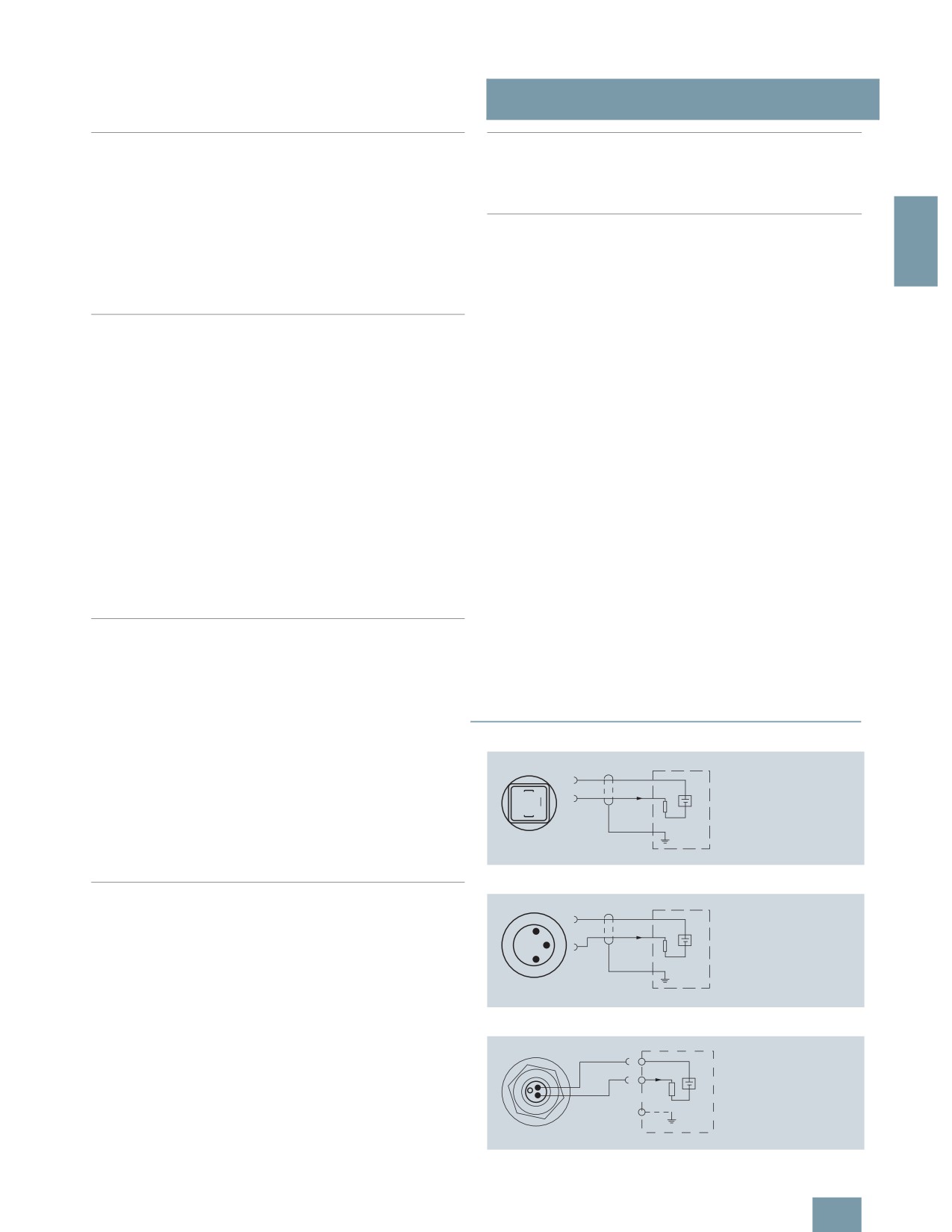
Connection with current output 4 ... 20 mA and plug to EN 175301-803-A
Certificates and approvals
Approval
CE conformity
Connection: 1 (+),
1+
I
3 (-)
3
O
+
2
R
UB
IO Output current
L
1
3-
RL Load
UB Power supply
Connection with current output 4 ... 20 mA and round connector
Connection: 1 (+, brown),
1+
2 (-, green)
I
O
+
2-
UB
IO Output current
RL
UB Power supply
RL Load
Connection with current output 4 ... 20 mA and permanently fixed cable
2/13

SITRANS P measuring instruments for pressure
Transmitters for gage, absolute and differential pressure
SITRANS P250 for differential pressure
Connection: 1 (+UB),
Round connector
1+
+
2 (-),
EN 60130-9
1
UB
3 (+U0)
3
2+
RL
2
UO
UO Output voltage
3-
RL Load
UB Power supply
2
Connection with voltage output 0 ... 5 V DC (0 ... 10 V DC) and plug to EN
175301-803-A
1
Connection: 1 (+UB, brown),
U
+
2 (+U0, green),
3
O
3
UB
3 (-, white)
2
2
R
L
UO Output voltage
1
UB Power supply
RL Load
Connection with voltage output 0 ... 5 V DC (0 ... 10 V DC) and round con-
nector
Connection: 1 (+UB),
1+
UO
+
2 (-),
3+
UB
3 (+U0)
R
L
Uo Output voltage
2-
UB Power supply
RL Load
SITRANS P250 differential pressure transmitter with round connector to
EN 60130-9, dimensions in mm (inch)
Connection with voltage output 0 ... 5 V DC (0 ... 10 V DC) and perma-
nently fixed cable
Cable
■Dimensional drawings
Socket outlet
EN 175301-803-A
Stainless
SITRANS P250 differential pressure transmitter with cable, dimensions in
P2
mm (inch)
P1
M 4
44 (1.7)
20 (0.79)
X
SITRANS P250 differential pressure transmitter with socket outlet to
EN 175301-803-A, dimensions in mm (inch)
2/14

SITRANS P measuring instruments for pressure
Transmitters for gage, absolute and differential pressure
SITRANS P250 for differential pressure
Process connections
Ø
Width across
L
X
flats
[mm]
[inch]
[mm]
[inch]
[mm]
[inch]
Pipe union with screw-in nipple for outer pipe
6
a = 10
24
65
L
(stainless steel 1.4305/AISI 303)
b = 12
8
a = 12
26
67
2
b = 14
a
b
Female thread G1/8
-
a = 14
12
53
L
(stainless steel 1.4305/AISI 303)
G1/8
a
Pipe union with screw-in nipple for outer pipe
6
a = 10
24
65
L
(CuZn nickel-plated)
b = 12
8
a = 12
25
66
b = 14
a
b
Hose connection for hose (CuZn nickel-plated,
4
a = 10
20
61
stainless steel 1.4571/AISI 316TI)
L
6
a = 10
25
66
a
Male thread G1/8
-
a = 10
20
61
L
(CuZn nickel-plated)
b = 12
a
b
Male thread G1/8
-
a = 14
18
59
L
7/16-20 UNF (CuZn nickel-plated)
a
2/15

SITRANS P measuring instruments for pressure
Transmitters for gage, absolute and differential pressure
SITRANS P250 for differential pressure
Order No.
Order code
■Selection and ordering data
SITRANS P 250 pressure transmitter for differential pressure
7MF1
64
1
-
7
7770
-
7
770
7
7
7
Accuracy ≤ 1 %, wetted parts ceramic/stainless steel 1.4301,
scope of delivery: transmitter, mounting bracket and instruction manual, without explosion protection
Measuring range
0 ... 0.1 bar
(0 ... 1.45 psi)
}
3
AA
2
0 ... 0.2 bar
(0 ... 2.90 psi)
}
3
AC
0 ... 0.25 bar
(0 ... 3.63 psi)
}
3
AD
0 ... 0.3 bar
(0 ... 5.35 ps)
}
3
AE
0 ... 0.4 bar
(0 ... 5.80 psi)
}
3
AF
0 ... 0.5 bar
(0 ... 7.25 psi)
}
3
AG
0 ... 0.6 bar
(0 ... 8.70 psi)
}
3
AH
0 ... 1.0 bar
(0 ... 14.5 psi)
}
3
BA
0 ... 1.6 bar
(0 ... 23.2 psi)
}
3
BB
0 ... 2.5 bar
(0 ... 36.3 psi)
}
3
BD
0 ... 4.0 bar
(0 ... 58.0psi)
}
3
BE
0 ... 6.0 bar
(0 ... 87.0 psi)
}
3
BG
0 ... 10.0 bar
(0 ... 145 psi)
}
3
CA
0 ... 16.0 bar
(0 ... 232 psi)
}
3
CB
0 ... 25.0 bar
(0 ... 363 psi)
}
3
CD
Output signal
4 ... 20 mA
}
0
0 ... 5 V DC
1
0 ... 10 V DC
2
Electrical connection
• Plug acc. to EN 175 301-803-A (suitable coupling included in scope of delivery)
}
1
• Round connector acc. to EN 60139-9
2
• Cable 1.5 m with cable gland
3
Process connection
• Without connections, female thread 1/8-27 NPT
}
A
• Hose connection
- CuZn nickel-plated, for hose ∅ 4 mm
B
- CuZn nickel-plated, for hose ∅ 6 mm
C
- PVDF, for hose ∅ 6 mm
D
• Pipe union
- CuZn nickel-plated, for pipe ∅ 6 mm
E
- Stainless steel 1.4304, for pipe ∅ 6 mm
F
- CuZn nickel-plated, for pipe ∅ 8 mm
G
- Stainless steel 1.4304, for pipe ∅ 8 mm
H
• Male thread, 7/16-20 UNF (CuZn nickel-plated)
L
• Adapter
- Inner, G1/8 (stainless steel), for pipe ∅ 6 mm
M
- Outer, with union nut, for pipe ∅ 6 mm
N
sealing material
• Fluoro rubber (Viton/FPM)
}
A
• Ethylene propylene diene monomer rubber (EPDM)
B
• Nitrile butadiene rubber (NBR)
C
• Silicone rubber (MVQ)
D
• Neoprene (CR)
E
Weitere Ausführungen
Kurzangabe
Please add "-Z" to Order No. and specify Order code(s).
Quality inspection certificate (Factory calibration) to IEC 60770-2 supplied
C11
} Available ex stock
2/16

SITRANS P measuring instruments for pressure
Transmitters for gage, absolute and differential pressure
ZD series for gage and absolute pressure
At the rear of the housing is the electrical connection for the volt-
■Overview
age supply using a current loop 4 ... 20 mA. The connection is
made with a plug connector.
At the front of the housing is the 5-digit display behind a glass
cover. Underneath the display are the 3 keys for parameterizing
the pressure transmitter. Above the display are a green and a red
LED for indicating the operating status.
2
The ZD pressure transmitter is available in two versions (see "Di-
mension drawing"):
In the radial version (type A) the display is fitted in parallel with
the process connection. The display can be rotated by up to
±120° relative to the process connection.
In the axial version (type B) the display is at right angles to the
process connection. The display can be rotated by 360° relative
to the process connection.
■Function
-
+*
!
+*
"*
."
()*
SITRANS P pressure transmitters, ZD series, are for measuring
the gage pressure, absolute pressure and level of liquids and
%3
++
,
gases.
/
+,"
They are used to indicate and monitor the pressure measured at
*)(
(
0 ###
1(
$
2
(
the point of installation. ZD pressure transmitters are available in
an axial and a radial version.
%3
"
4
4
1
()*
(
!
&
■ Benefits
*)(
&
++
,
, 1
4
1
• Robust stainless steel housing with 2 connection versions
+,"
5
&
1
(
• Integrated display with status messages
4
4
&
"*
41
!&
5!1
• Thin-film measuring cell with ceramic diaphragm
-
+*
4
1
1 !
!
+*
4
1
1 &
• 2-wire system, 4 ... 20 mA
"
1 1
2
• Parameterizable using keys underneath the housing cover
."
,
4
1
4
!1
• Range adjustment 1:5 (max. 1:10)
SITRANS P pressure transmitters, ZD series, mode of operation
• Measuring accuracy < 0.25% (typical)
Mode of operation
■Application
The ZD pressure transmitter has a thin-film strain gage which is
mounted on a ceramic diaphragm.
The ZD is a configurable pressure transmitter for measuring the
gage and absolute pressure of gases, liquids and vapor.
The measuring cell is temperature-compensated.
It is equipped with a display for indicating the pressure value at
Functions
the point of installation.
The ZD pressure transmitter has a 5-digit display behind a glass
SITRANS P pressure transmitters, ZD series, are used in the fol-
cover. The following data are shown on the display:
lowing industrial areas for example:
• Measured pressure
• Chemical industry
• Technical pressure dimension (default setting: bar)
• Mechanical engineering
• Limit violation in upward or downward direction, indicated by
• Food industry
LED and arrow symbols in the display
• Pharmaceutical industry
The pressure transmitter is set using the 3 input keys behind the
• Shipbuilding
glass cover underneath the display.
• Water supply
The key "M" is used to select the operating mode. Following
modes of operation are available:
■Design
• Measured value
The pressure transmitter is comprised of a thin-film measuring
• Password
cell with a ceramic diaphragm, an electronics board and a digi-
• Dimension
tal indicator.
• Start and end of scale
All parts are accommodated in a stainless steel field housing
• Upper and lower limit value
(∅ 80 mm) with a glass cover and stainless steel process con-
• Zero adjustment
nection.
2/17

SITRANS P measuring instruments for pressure
Transmitters for gage, absolute and differential pressure
ZD series for gage and absolute pressure
• Upper and lower current saturation limit
Rated conditions
• Electrical damping
Ambient conditions
The other two keys are used to set the values in the individual op-
• Ambient temperature
-25 ... +85 °C (-13 ... +185 °F)
erating modes.
• Storage temperature
-40 ... +85 °C (-40 ... +185 °F)
Two LED indicators are fitted above the display to monitor the set
Medium conditions
2
range and the status.
• Process temperature
-30 ... +100 °C (-22 ... +212 °F)
The green LED signals that the measured pressure lies within the
Degree of protection
IP65 to EN 60529
set limits. The red LED lights up when the measured pressure
lies outside the set limits and when there is an error.
Electromagnetic compatibility
• Emitted interference and interfer-
To EN 61326/A1 appendix A
■ Technical specifications
ence immunity
(1998)
SITRANS P pressure transmitters, ZD series
Displays and controls
Mode of operation
Display
LCD, max. 5 digits, digit height
9 mm
Measuring principle
Thin-film strain gage
Decimal point
Freely parameterizable
Input
Limit values
Freely parameterizable
Measured variable
Gage and absolute pressure
Limit violation display
Red LED and message on LCD
Measured range
Resolution
(↑ symbol /↓ symbol in case of
limit violation in upward / down-
0 ... 2 bar (0 ... 29 psi)
0.6 mbar (0.008 psi)
ward direction)
0 ... 10 bar (0 ... 145 psi)
3 mbar (0.044 psi)
Parameterization
With 3 keys
0 ... 50 bar (0 ... 725 psi)
15 mbar (0.218 psi)
Units
mA or % or physical variable
0 ... 200 bar (0 ... 2900 psi)
60 mbar (0.9 psi)
(default setting: bar)
0 ... 400 bar (0 ... 5800 psi)
120 mbar (1.8 psi)
Other dimensions: mbar, kPa,
MPa, mmH20, mH20, psi, inH20,
Measured range
Overload limit
mmHg, kg/cm², torr, atm
0 ... 2 bar (0 ... 29 psi)
5 bar (72.5 psi)
Between 0.1 and 100 s
Damping
(increment: 0.1 s) freely parame-
0 ... 10 bar (0 ... 145 psi)
25 bar (363 psi)
terizable
0 ... 50 bar (0 ... 725 psi)
120 bar (1740 psi)
Design
0 ... 200 bar (0 ... 2900 psi)
500 bar (7250 psi)
Weight
≈0.6 kg (≈1.32 lb)
0 ... 400 bar (0 ... 5800 psi)
600 bar (8700 psi)
Electrical connection
Using 2-pole plug connector with
Range adjustment (turndown)
5:1
M16x1.5-Cable inlet to
EN 175301-803A, plastic
Output
Process connection
• Male thread G½B and female
Output signal
4 ... 20 mA
thread G1/8B
Lower current limit
min. 3.6 mA
• G½B to EN 837-1
Upper current limit
max. 23 mA
• Female thread: ½-14 NPT
Version of housing/process connec-
• Radial (type A), can be swiveled
Output protected against
Reversed polarity, overvoltage
tion
by max. ±120° (α)
and short-circuiting
Max. load
R B = (UH - 12 V) / 0.023 A
• Axial (type B), can be swiveled
by max. ±360°
Voltage measurement
Linear rising
Material
Measuring accuracy
To EN 60770-1
Non-wetted parts materials
Error in measurement (including
< 0.25% of full-scale value (typi-
non-linearity, hysteresis and repeat-
cal), max. 0.5%
• Field housing
Ø 80 mm (3.15 inch), stainless
ability, at 25 °C (77 °F))
steel mat. No. 1.4016
• Cover
Stainless steel, mat. No. 1.4016
Adjustment time
< 100 ms
with glass
Long-term drift
0.25% of full scale value/year
Wetted parts materials
Influence of ambient temperature
< ±0.25%/10 K (< ±0.25%/10 K)
of full-scale value
• Measuring cell
Al2O3
Vibration influence
0.05%/g to 500 Hz in all directions
• Gasket
Viton
(to IEC 68-2-64)
• Process connection
Stainless steel, mat. No.
Power supply effect
< ±0.01%/V of full-scale value
1.4571/316Ti
Power supply
Terminal voltage on pressure trans-
12 ... 30 V DC
mitter (UH)
Certificate and approvals
Classification according to pressure
For gases of fluid group 1 and liq-
equipment directive 97/23/EC
uids of fluid 1; complies with
requirements of article 3, para-
graph 3 (sound engineering prac-
tice)
2/18

SITRANS P measuring instruments for pressure
Transmitters for gage, absolute and differential pressure
ZD series for gage and absolute pressure
■Dimensional drawings
67
$%#
%%
67
$%#
%%
0; $ #::%
07$; $
#<
%
2
, ?@ $;
,
8= >
, ?@ $;
8= >
9 :
-8
8 0= >
-8
- )7
+= 7%:
SITRANS P pressure transmitters, ZD series, dimensional drawing, dimensions in mm (inch)
■Schematics
SITRANS P pressure transmitters, ZD series, connection diagram
2/19

SITRANS P measuring instruments for pressure
Transmitters for gage, absolute and differential pressure
ZD series for gage and absolute pressure
Selection and Ordering data
Order No. Ord. Code
Selection and Ordering data
Order Code
SITRANS P pressure transmitters, ZD
7MF 1 5
80
-
Further designs
series for gage and absolute pressure
Please add "Z" to Order No. and specify Order
Conformity error 0.25%, range adjustment
77770
7
7
7
code(s) and plain text.
1 : 5 (max. 1 : 10), housing and process
C1 1
Quality inspection certificate (Factory cali-
connection made of stainless steel,
2
bration) to IEC 60770-2 supplied
membrane made of ceramic, 2-wire system,
output 4 ... 20 mA
Factory certificate
C1 4
to EN 10204-2.2 supplied
Input variable
Gage pressure
}
1
Oxygen application, oil and grease-free
E10
cleaned
Absolute pressure
}
2
F)
(only in conjunction with the sealing material
Viton between sensor and enclosure and only
Measured range
Span
in conjunction with measuring ranges >= 1
0 ... 2 bar
0 ... 0.4 / 2 bar
} D
bar g and 1 bar abs)
(0 ... 29 psi)
(0 ... 5.8 / 29 psi)
Sealing material FEP between sensor and
E20
0 ... 10 bar
0 ... 2 / 10 bar
} E
housing, instead of Viton
(0 ... 145 psi)
(0 ... 5.8 / 145 psi)
max. operating pressure 15 bar (218 psi),
0 ... 50 bar
0 ... 10 / 50 bar
} F
max. measuring temperature -10 ... +50 °C
(0 ... 725 psi)
(0 ... 145 / 725 psi)
Additional data
0 ... 200 bar
0 ... 40 / 200 bar
} G
Please add "Z" to Order No. and specify Order
(0 ... 2900 psi)
(0 ... 580 / 2900 psi)
code(s) and plain text.
0 ... 400 bar
0 ... 80 / 400 bar
} H
Measuring range to be set,
Y01
(0 ... 5800 psi)
(0 ... 1160 / 5800 psi)
specify in plain text:
Other version (on request)
Z
J
1
Y
Y01: ... up to ... mbar, bar, kPa, MPa, psi
add Order Code and plain text:
Process connection:
TAG number made of stainless steel
Y15
Process connection
Accessories
Order No.
G½B male thread and G1/8B female thread
} A
Quality inspection certificate (Factory
7MF1564-8CC11
G½B to EN 837-1
F)
B
calibration) to IEC 60770-2 supplied later,
Female thread ½-14 NPT
F)
C
specify factory of transmitter.
G 1“ male thread
F)
M
} Available ex stock
Design
F) Subject to export regulations AL: 9I999, ECCN: N.
Process connection vertically downwards,
}
1
thread in connector M16x1.5
Process connection horizontally to rear,
2
thread in connector M16x1.5
Process connection vertically downwards,
}
3
thread in connector ½"-14 NPT
Process connection horizontally to rear,
4
thread in connector ½"-14 NPT
2/20
SITRANS P measuring instruments for pressure
Transmitters for food, pharmaceuticals and biotechnology
SITRANS P Compact
for gage and absolute pressure
■Overview
■Application
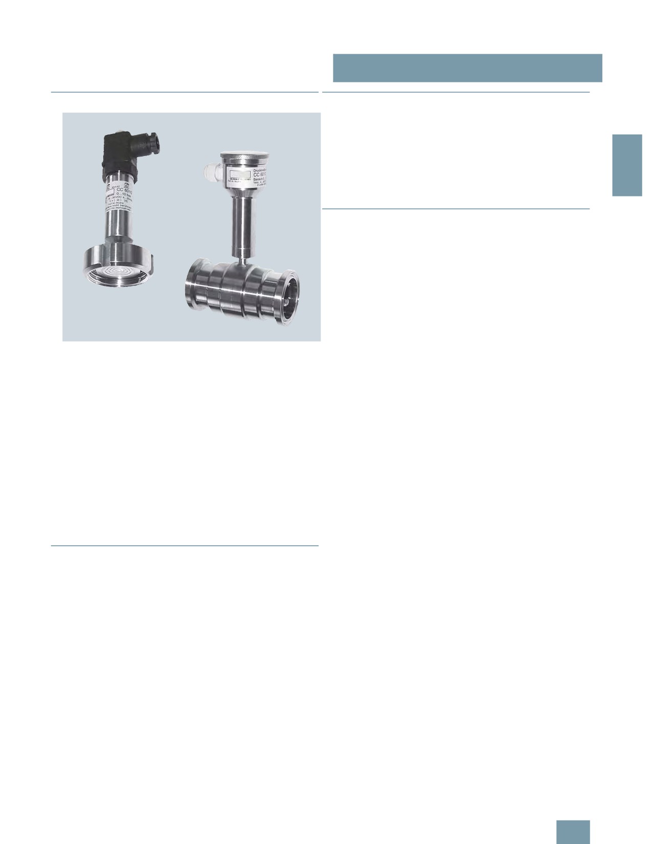
The SITRANS P Compact pressure transmitter is designed for
the special requirements of the food, pharmaceutical and bio-
technology industries.
The use of high-grade materials guarantees compliance with hy-
2
giene regulations.
The SITRANS P Compact pressure transmitter is available in
many versions. Exact adaptation of the pressure transmitter to
conditions at the place of use is thus possible
■Design
The electronics is potted to protect it against moisture, corrosive
atmospheres and vibration.
Notes on operating the pressure transmitter
Compensation of internal atmospheric pressure
Compensation of the internal atmospheric pressure of the
SITRANS P Compact pressure transmitters is performed as fol-
lows:
• in the plug versions by means of the screwed gland (IP65)
• in the field housings by means of an integral sintered filter
(IP65) or a vented cable (IP67)
The SITRANS P Compact pressure transmitter is designed for
• in versions with cable outlet by means of a vented cable (IP67)
the special requirements of the food, pharmaceutical and bio-
technology industries.
In the absolute pressure range there is no need for compensa-
tion with respect to atmospheric pressure.
The use of high-grade materials guarantees compliance with hy-
giene regulations.
Note: These degrees of protection are only achieved under the
following conditions:
Particular value has been placed on a high surface quality. It is
therefore possible, for example, to guarantee roughness values
• if the pressure transmitter is installed correctly
down to Ra = 0.4 μm (1.57 ⋅ 10-5 inch) in the wetted area
• if the screwed glands are securely tightened
(welded seam area Ra < 0.8 μm (3.15 ⋅ 10-5 inch)). The system
• if the cable diameters agree with the nominal diameters of the
can be electropolished in addition.
gaskets in the housing
A further important feature is the hygiene-based design of the
Note: The integral EMC measures are only effective if the earth
process connection by means of various aseptic connections.
connection is made correctly.
The completely welded stainless steel housing can be designed
CE marking
up to degree of protection IP67.
The CE marking of the pressure transmitter certifies compliance
Using appropriate thermal decouplers, the SITRANS P Compact
with the guidelines of the European Council (9/336/EC), the EMC
pressure transmitter can be used for process temperatures up to
law (13.11.1992), as well as the applicable generic standards.
200 °C (392 °F).
Interference-free operation in systems and plants is achieved
only if the specifications for shielding, earthing, cable routing
■ Benefits
and electrical isolation are observed during installation and as-
• Measuring ranges from 0 to 160 mbar (0 to 2.32 psi) to 0 to
sembly.
40 bar (0 to 580 psi)
Hazardous areas
• Linearity error including hysteresis < +0.2% of full-scale value
Note: Electrical equipment in hazardous areas must only be in-
• Piezo-resistive measurement system, vacuum-proof and over-
stalled and operated by trained personnel.
load-proof
• Hygiene-based design according to EHEDG, FDA and GMP
Modifications to units and connections result in cancellation of
recommendations
the explosion protection and guarantee.
• Material and surface quality according to hygiene require-
With intrinsically-safe circuits, make sure that equipotential
ments
bonding exists throughout the complete cabling inside and out-
side of the hazardous area. The limits specified in the ATEX ap-
• Wetted parts made of stainless steel; completely welded
proval must be observed.
• Signal output 4 to 20 mA (0 to 20 mA as option)
• Stainless steel housing with degree of protection IP65 (IP67 as
option)
• Process temperature up to 200 °C (392 °F)
• Explosion protection II 2G EEx [ib] IIC T6 to ATEX
• Easy and safe to clean
2/21
SITRANS P measuring instruments for pressure
Transmitters for food, pharmaceuticals and biotechnology
SITRANS P Compact
for gage and absolute pressure
Rated conditions
■Function
Installation conditions
The process pressure acts on a piezo-resistive semiconductor
measuring bridge through a remote seal and a transmission liq-
• Mounting position
Any, vertical as standard
uid. The pressure transmitter converts the pressure values into a
Ambient conditions
load-independent current.
• Ambient temperature
-10 ... +70 °C (14 ... 158 °F)
2
A compensation network makes the output signal largely inde-
• Storage temperature
-10 ... +90 °C (14 ... 194 °F)
pendent of the ambient temperature. As a result of a specially
adapted remote seal connection with minimized volume, the in-
• Process temperature
Max. 200 °C (392 °F), depends
on design
fluence of the process temperature on the output signal is
greatly reduced compared to a conventional screw connection.
• Degree of protection (to EN 60529)
IP65, optional IP67
The pressure transmitters can be powered with a non-regulated
• Electromagnetic compatibility
DC voltage of 10 to 30 V. Output signals common to measuring
- Emitted interference
To EN 50081 Part 1, issue 1993
technology are available.
(residential and industrial areas).
The unit has no own emissions.
■ Technical specifications
- Interference immunity to
EN 50082 Part 2, issue March
1995 (industrial areas)
Pressure transmitters for food, pharmaceuticals and biotechnology
Design
Mode of operation
Weight (without remote seal)
Measuring principle
Piezo-resistive
• Field housing
≈ 460 g (≈ 1.01 lb)
Input
• Housing with plug
≈ 200 g (≈ 0.44 lb)
Measured variable
Gage or absolute pressure
Housing
Measured range
0 ... 160 mbar (0 ... 2.32 psi)
• Designs
• Field housing IP65 or IP67, with
0 ... 40 bar (0 ... 580 psi)
screwed gland
Output
• Angled plug DIN 43650, IP65
• Cable connection, IP67
Output signal
• Round plug connector M12,
• Two-wire system
4 ... 20 mA
IP65
• Three-wire system
0 ... 20 mA
• Material
Stainless steel, mat.
Measuring accuracy
To EN 60770-1
No. 1.4404/1.4305
Linearity error including hysteresis
≤ 0.2% of full-scale value
Material of union nut
Polyamide (with electrical con-
(reference point adjustment)
nection using plug or cable)
Electronics unit potted with sili-
Adjustment accuracy
≤ ± 0.2% of full-scale value
cone
Adjustment time
< 20 ms
Internal ventilation for measuring
Influence of ambient temperature
ranges < 16 bar (< 232 psi),
through housing thread or con-
On th enclosure
nection cable depending on
design
• Zero
< 0.2%/10 K of full-scale value
Process connection
• Measured span
< 0.2%/10 K of full-scale value
• Versions
See Ordering data
On the process connection (remote
Zero error (depends on design)
seal)
• Material of coupling
Stainless steel, mat.
No. 1.4404/316L
• Flange remote seal
Power supply
- DN 25 / 1"
4.8 mbar/10 K (0.070 psi/10 K)
Terminal voltage on transmitter
10 ... 30 V DC
- DN 32 / 1¼”
2.3 mbar/10 K (0.033 psi/10 K)
Rated voltage
24 V DC
- DN 40 / 1½”
1.6 mbar/10 K (0.023 psi/10 K)
Certificate and approvals
- DN 50 / 2"
0.6 mbar/10 K (0.009 psi/10 K)
Classification according to pressure
For gases of fluid group 1 and liq-
• Clamp-on seal
equipment directive
uids of fluid group 1; complies
- DN 25 / 1"
9.5 mbar/10 K (0.138 psi/10 K)
(DRGL 97/23/EC)
with the requirements of article 3,
paragraph 1 (appendix 1);
- DN 32 / 1¼”
4.1 mbar/10 K (0.060 psi/10 K)
assigned to category III, confor-
- DN 40 / 1½”
3.9 mbar/10 K (0.057 psi/10 K)
mity evaluation module H by the
TÜV Nord
- DN 50 / 2"
3.9 mbar/10 K (0.057 psi/10 K)
Explosion protection
The zero error specified for the process connection should be consid-
ered as a guideline for a standard design. We will produce a detailed
• Intrinsic safety "i"
TÜV 03 ATEX 2099 X
system calculation on request. Systems with reduced remote seal errors
- Identification
Ex II 2G EEx ib IIC T6
are available on request.
2/22

SITRANS P measuring instruments for pressure
Transmitters for food, pharmaceuticals and biotechnology
SITRANS P Compact
for gage and absolute pressure
Selection and Ordering data
Order No.
Ord. code
Selection and Ordering data
Order No.
Ord. code
SITRANS P Compact pressure trans-
7
MF8010 -
SITRANS P Compact pressure trans-
7MF8010 -
mitters for pressure and absolute
mitters for pressure and absolute
pressure with diaphragm flush at front
pressure with diaphragm flush at front
2-wire system
1
7777-7777
7
7
7
2-wire system
17777-7777
7
7
7
Process temperature up to 140 °C
Process temperature up to 140 °C
(284 °F)
(284 °F)
2
Accuracy: 0.2% of full-scale value
Accuracy: 0.2% of full-scale value
Output 4 ... 20 mA
Output 4 ... 20 mA
Diaphragm seal
Diaphragm seal
with quick-release clamp
with aseptic connection
Milk pipe union to DIN 11851 with
Aseptic screwed gland to DIN 11864-1,
slotted union nut
form A,
• DN 25
AD
with slotted union nut
• DN 32
AE
• 1 inch
PM
• DN 40
AF
• 1½ inch
PN
• DN 50
AG
• 2 inch
PP
• DN 65
AH
• 2½ inch
PQ
Milk pipe union to DIN 11851 with
Aseptic screwed gland to
threaded socket
DIN 11864-1, form A
with threaded socket
• DN 25
BD
• 1 inch
QM
• DN 32
BE
• 1½ inch
QN
• DN 40
BF
• 2 inch
QP
• DN 50
BG
• 2½ inch
QQ
• DN 65
BH
Aseptic screwed NEUMO
Clamp connection to DIN 32676
with slotted union nut1)
• DN 25
CD
• DN 25
RD
• DN 40
CF
• DN 32
RE
• DN 50
CG
• DN 40
RF
Clamp connection to ISO 2852
• DN 50
RG
• 1 inch
DM
Aseptic screwed NEUMO
• 1½ inch
DN
with threaded socket1)
• 2 inch
DP
• DN 25
SD
• 2½ inch
DQ
• DN 32
SE
IDF standard with slotted union nut
• DN 40
SF
• 1 inch
EM
• DN 50
SG
• 1½ inch
EN
Aseptic screwed NEUMO
• 2 inch
EP
with clamp connection, form R1)
IDF standard with threaded socket
• DN 25
TD
• 1 inch
FM
• DN 32
TE
• 1½ inch
FN
• DN 40
TF
• 2 inch
FP
• DN 50
TG
SMS standard with slotted union nut
Aseptic screwed NEUMO
• 1 inch
GM
with clamp connection, form V1)
• 1½ inch
GN
• DN 25
UD
• 2 inch
GP
• DN 32
UE
SMS standard with threaded socket
• DN 40
UF
• 1 inch
HM
• DN 50
UG
• 1½ inch
HN
Special version
ZA
J
1
Y
• 2 inch
HP
(add Order code and plain text)
DRD flange, without welding-type flange
Filling liquid
• DN 50, PN 40
JH
Vegetable oil
1
Varivent connection (Tuchenhagen)
medicinal white oil
2
• D = 50, for Varivent housing DN 25 and
KF
1 inch
Food oil, FDA-listed
3
• D = 68, for Varivent housing
KL
Special version
9
L
1
Y
DN 40 ... DN 125 and 1½ ... 6 inch
(add Order code and plain text)
Special version
ZA
J
1
Y
Output signal
(add Order code and plain text)
4 ... 20 mA
1
Filling liquid
Special version
9
M
1
Y
Vegetable oil
1
(add Order code and plain text)
medicinal white oil
2
1) Please specify as well:
Food oil, FDA-listed
3
Connections for pipes: R01, R02 or R03,
see table "Further designs" on next page
Special version
9
L
1
Y
(add Order code and plain text)
Output signal
4 ... 20 mA
1
Special version
9
M
1
Y
(add Order code and plain text)
2/23

SITRANS P measuring instruments for pressure
Transmitters for food, pharmaceuticals and biotechnology
SITRANS P Compact
for gage and absolute pressure
Selection and Ordering data
Order No.
Ord. code
Selection and Ordering data
Order No.
Ord. code
SITRANS P Compact pressure trans-
7
MF8010 -
SITRANS P Compact pressure trans-
7MF8010 -
mitters for pressure and absolute
mitters for pressure and absolute
pressure with diaphragm flush at front
pressure with diaphragm flush at front
2-wire system
1
7777-
7777
7
7
7
2-wire system
17777-7777
7
7
7
Process temperature up to 140 °C
Process temperature up to 140 °C
2
(284 °F)
(284 °F)
Accuracy: 0.2% of full-scale value
Accuracy: 0.2% of full-scale value
Output 4 ... 20 mA
Output 4 ... 20 mA
Housing design (stainless steel mat.
Measured range
Overload pres-
No. 1.4404/316L) / electr. connection
sure
Housing with angled plug to DIN 43650,
1
(continued)
IP65
-1 ... 9 bar g
30 bar g
GA
Housing with round plug M12, IP65,
2
(-14.5 ... 130.5 psi g) (435 psi g)
union nut made of polyamide
-1 ... 15 bar g
50 bar g
GB
(-14.5 ... 217.6 psi g) (725 psi g)
Housing with round plug M12, IP65,
3
union nut made of stainless steel
0 ... 1 bar a
10 bar a
F)
HA
(0 ... 14.5 psi a)
(145 psi a)
Stainless steel field housing (small) with
4
cable gland, IP65
0 ... 1.6 bar a
10 bar a
F)
HB
(0 ... 23.2 psi a)
(145 psi a)
Stainless steel field housing (small) with
5
0 ... 2.5 bar a
16 bar a
F)
HC
cable gland, IP67
(0 ... 36.3 psi a)
(232 psi a)
Internal ventilation for measuring ranges
0 ... 4 bar a
16 bar a
F)
HD
< 10 bar (< 145 psi)
(0 ... 58 psi a)
(232 psi a)
Measured range
Overload pressure
0 ... 6 bar a
30 bar a
F)
HE
0 ... 160 mbar g
2 bar g
BB
(0 ... 87 psi a)
(435 psi a)
(0 ... 2.32 psi g)
(29 psi g)
0 ... 10 bar a
30 bar a
F)
JA
0 ... 250 mbar g
2 bar g
BC
(0 ... 145 psi a)
(435 psi a)
(0 ... 3.63 psi g)
(29 psi g)
0 ... 400 mbar g
6 bar g
BD
Special version
F)
ZA
P
1
Y
(0 ... 5.8 psi g)
(87 psi g)
(add Order code and plain text)
0 ... 600 mbar g
6 bar g
BE
Explosion protection
(0 ... 8.7 psi g)
(87 psi g)
without
1
0 ... 1 bar g
10 bar g
CA
with, to ATEX 100a, II 2 G, EEx ib IIC T6
2
(0 ... 14.5 psi g)
(145 psi g)
Further designs
Order code
0 ... 1.6 bar g
10 bar g
CB
(0 ... 23.2 psi g)
(145 psi g)
Please add "-Z" to Order No. and specify
0 ... 2.5 bar g
16 bar g
CC
Order code
(0 ... 36.3 psi g)
(232 psi g)
Hygiene version
P01
0 ... 4 bar g
16 bar g
CD
Roughness of process connection:
(0 ... 58 psi g)
(232 psi g)
Foil Ra < 0.8 μm (3.15·10-8 inch);
0 ... 6 bar g
30 bar g
CE
Welded seams Ra < 1.5 μm
(0 ... 87 psi g)
(435 psi g)
(5.9·10-8 inch)
0 ... 10 bar g
30 bar g
DA
Integral cooling element
K01
(0 ... 145 psi g)
(435 psi g)
Process temperature max. 200 °C
0 ... 16 bar g
50 bar g
DB
(392 °F) instead of 140 °C (284 °F)
(0 ... 232 psi g)
(725 psi g)
Connections for pipe
0 ... 25 bar g
50 bar g
DC
(0 ... 363 psi g)
(725 psi g)
Pipes to DIN 11850
R01
0 ... 40 bar g
70 bar g
DD
ISO pipes to DIN 2463
R02
(0 ... 580 psi g)
(1015 psi g)
Pipes to O. D. Tubing "BS 4825 Part 1"
R03
-160 ... 0 mbar g
2 bar g
EB
Certificates
(-2.32 ... 0 psi g)
(29 psi g)
Quality inspection certificate (Factory
C11
-250 ... 0 bar g
2 bar g
EC
calibration) to IEC 60770-2
(-3.73 ... 0 psi g)
(29 psi g)
C12
Acceptance test certificate to
-400 ... 0 bar g
6 bar g
ED
EN 10204-3.1
(-5.8 ... 0 psi g)
(87 psi g)
Use of FDA-listed remote seal filling liq-
C17
-600 ... 0 bar g
6 bar g
EE
uids certified by factory certificate to
(-8.7 ... 0 psi g)
(87 psi g)
EN 10204-2.2
-1 ... 0 bar g
10 bar g
FA
Roughness depth measurement Ra
C18
(-14.5 ... 0 psi g)
(145 psi g)
certified by factory certificate to
-1 ... 0.6 bar g
10 bar g
FB
EN 10204-3.1
(-14.5 ... 8.7 psi g)
(145 psi g)
-1 ... 1.5 bar g
16 bar g
FC
Certification to EHEDG for clamp-on
C19
(-14.5 ... 21.8 psi g) (232 psi g)
seals with aseptic screwed gland
-1 ... 3 bar g
16 bar g
FD
to DIN 11864
(-14.5 ... 43.5 psi g) (232 psi g)
F) Subject to export regulations AL: 9I999, ECCN: N.
-1 ... 5 bar g
30 bar g
FE
(-14.5 ... 72.5 psi g) (435 psi g)
2/24

SITRANS P measuring instruments for pressure
Transmitters for food, pharmaceuticals and biotechnology
SITRANS P Compact
for gage and absolute pressure
Selection and Ordering data
Order No.
Ord. code
Selection and Ordering data
Order No.
Ord. code
SITRANS P Compact pressure trans-
7MF8010 -
SITRANS P Compact pressure trans-
7MF8010 -
mitters for pressure and absolute
mitters for pressure and absolute
pressure with clamp-on remote seal
pressure with clamp-on remote seal
2-wire system
27777-
7777
7
7
7
2-wire system
27777-7777
7
7
7
Process temperature up to 140 °C
Process temperature up to 140 °C
(284 °F)
(284 °F)
2
Accuracy: 0.2% of full-scale value
Accuracy: 0.2% of full-scale value
Output 4 ... 20 mA
Output 4 ... 20 mA
Clamp-on remote seal (screwed gland
Clamp-on seal
at both ends)
with aseptic connection
with quick-release clamps
Aseptic screwed gland to
Milk pipe union to DIN 11851 with
DIN 11864-1, form A
threaded socket
with threaded socket
• DN 25
AD
• 1 inch
QM
• DN 32
AE
• 1½ inch
QN
• DN 40
AF
• 2 inch
QP
• DN 50
AG
Aseptic screwed NEUMO
• DN 65
AH
with threaded socket1)
Clamp connection to DIN 32676
• DN 25
SD
• DN 25
CD
• DN 32
SE
• DN 32
CE
• DN 40
SF
• DN 40
CF
• DN 50
SG
• DN 50
CG
• DN 65
SH
• DN 65
CH
Aseptic screwed NEUMO
with clamp connection, form R1)
Clamp connection to ISO 28521)
• DN 25
TD
• 1 inch
DM
• DN 32
TE
• 1½ inch
DN
• DN 40
TF
• 2 inch
DP
• DN 50
TG
• 2½ inch
DQ
Aseptic screwed gland SÜDMO
Special version
ZA
J
1
Y
with threaded socket W 501
(add Order code and plain text)
• 1 inch
VM
Filling liquid
• 1½ inch
VN
Vegetable oil
1
• 2 inch
VP
Medicinal white oil
2
Aseptic screwed gland SÜDMO
with clamp connection W 601
Food oil, FDA-listed
3
• 1 inch
WM
Special version
9
L
1
Y
• 1½ inch
WN
(add Order code and plain text)
• 2 inch
WP
Output signal
Special version
ZA
J
1
Y
4 ... 20 mA
1
(add Order code and plain text)
Special version
9
M
1
Y
Filling liquid
(add Order code and plain text)
Vegetable oil
1
1) Please note the internal diameter of the pipe. Please specify pipe classes
medicinal white oil
2
(see "Further designs")
Food oil, FDA-listed
3
Special version
9
L
1
Y
(add Order code and plain text)
Output signal
4 ... 20 mA
1
Special version
9
M
1
Y
(add Order code and plain text)
1) Please specify as well:
Connections for pipes: R01, R02 or R03,
see table "Further designs" on next page
2/25

SITRANS P measuring instruments for pressure
Transmitters for food, pharmaceuticals and biotechnology
SITRANS P Compact
for gage and absolute pressure
Selection and Ordering data
Order No.
Ord. code
Selection and Ordering data
Order No.
Ord. code
SITRANS P Compact pressure trans-
7
MF8010 -
SITRANS P Compact pressure trans-
7MF8010 -
mitters for pressure and absolute
mitters for pressure and absolute
pressure with clamp-on remote seal
pressure with clamp-on remote seal
2-wire system
2
7777-
7777
7
7
7
2-wire system
27777-7777
7
7
7
Process temperature up to 140 °C
Process temperature up to 140 °C
2
(284 °F)
(284 °F)
Accuracy: 0.2% of full-scale value
Accuracy: 0.2% of full-scale value
Output 4 ... 20 mA
Output 4 ... 20 mA
Housing design (stainless steel mat.
Measured range Overload pressure
No. 1.4404/316L) / electr. connection
(continued)
Housing with angled plug to DIN 43650,
1
-1 ... 9 bar g
30 bar g
GA
IP65, union nut made of polyamide
(-14.5 ... 130.5 psi g)(435 psi g)
Housing with round plug M12, IP65,
2
-1 ... 15 bar g
50 bar g
GB
union nut made of polyamide
(-14.5 ... 217.6 psi g)(725 psi g)
Housing with round plug M12, IP65,
3
union nut made of stainless steel
0 ... 1 bar a
10 bar a
F)
HA
(0 ... 14.5 psi a)
(145 psi a)
Stainless steel field housing (small) with
4
0 ... 1.6 bar a
10 bar a
F)
HB
cable gland, IP65
(0 ... 23.2 psi a)
(145 psi a)
Stainless steel field housing (small) with
5
0 ... 2.5 bar a
16 bar a
F)
HC
cable gland, IP67
(0 ... 36.3 psi a)
(232 psi a)
Internal ventilation for measuring ranges
0 ... 4 bar a
16 bar a
F)
HD
< 10 bar (< 145 psi)
(0 ... 58 psi a)
(232 psi a)
Measured range
Overload pressure
0 ... 6 bar a
30 bar a
F)
HE
0 ... 160 mbar g
2 bar g
BB
(0 ... 87 psi a)
(435 psi a)
(0 ... 2.32 psi g)
(29 psi g)
0 ... 10 bar a
30 bar a
F)
JA
0 ... 250 mbar g
2 bar g
BC
(0 ... 145 psi a)
(435 psi a)
(0 ... 3.63 psi g)
(29 psi g)
Special version
F)
ZA
P
1
Y
0 ... 400 mbar g
6 bar g
BD
(add Order code and plain text)
(0 ... 5.8 psi g)
(87 psi g)
0 ... 600 mbar g
6 bar g
BE
Explosion protection
(0 ... 8.7 psi g)
(87 psi g)
without
1
0 ... 1 bar g
10 bar g
CA
with, to ATEX 100a, II 2 G, EEx ib IIC T6
2
(0 ... 14.5 psi g)
(145 psi g)
Further designs
Order code
0 ... 1.6 bar g
10 bar g
CB
Please add "-Z" to Order No. and specify
(0 ... 23.2 psi g)
(145 psi g)
Order code
0 ... 2.5 bar g
16 bar g
CC
(0 ... 36.3 psi g)
(232 psi g)
Hygiene version
P01
0 ... 4 bar g
16 bar g
CD
Roughness of process connection:
(0 ... 58 psi g)
(232 psi g)
Foil Ra < 0.8 μm (3.15·10-8 inch);
0 ... 6 bar g
30 bar g
CE
Welded seams Ra < 1.5 μm
(0 ... 87 psi g)
(435 psi g)
(5.9·10-8 inch)
0 ... 10 bar g
30 bar g
DA
Integral cooling element
K01
(0 ... 145 psi g)
(435 psi g)
Process temperature max. 200 °C
0 ... 16 bar g
50 bar g
DB
(392 °F) instead of 140 °C (284 °F)
(0 ... 232 psi g)
(725 psi g)
Connections for pipe
0 ... 25 bar g
50 bar g
DC
Pipes to DIN 11850
R01
(0 ... 363 psi g)
(725 psi g)
ISO pipes to ISO 2463
R02
0 ... 40 bar g
70 bar g
DD
Pipes to O. D. Tubing "BS 4825 Part 1"
R03
(0 ... 580 psi g)
(1015 psi g)
Certificates
-160 ... 0 mbar g
2 bar g
EB
(-2.32 ... 0 psi g)
(29 psi g)
Quality inspection certificate (Factory
C11
calibration) to IEC 60770-2
-250 ... 0 bar g
2 bar g
EC
(-3.73 ... 0 psi g)
(29 psi g)
Acceptance test certificate to
C12
-400 ... 0 bar g
6 bar g
ED
EN 10204-3.1
(-5.8 ... 0 psi g)
(87 psi g)
Use of FDA-listed remote seal filling liq-
C17
-600 ... 0 bar g
6 bar g
EE
uids certified by factory certificate
(-8.7 ... 0 psi g)
(87 psi g)
to EN 10204-2.2
-1 ... 0 bar g
10 bar g
FA
Roughness depth measurement Ra
C18
(-14.5 ... 0 psi g)
(145 psi g)
certified by factory certificate
-1 ... 0.6 bar g
10 bar g
FB
to EN 10204-3.1
(-14.5 ... 8.7 psi g)
(145 psi g)
Certification to EHEDG for clamp-on
C19
-1 ... 1.5 bar g
16 bar g
FC
seals with aseptic screwed gland
(-14.5 ... 21.8 psi g) (232 psi g)
to DIN 11864
-1 ... 3 bar g
16 bar g
FD
(-14.5 ... 43.5 psi g) (232 psi g)
F) Subject to export regulations AL: 9I999, ECCN: N.
-1 ... 5 bar g
30 bar g
FE
(-14.5 ... 72.5 psi g) (435 psi g)
2/26
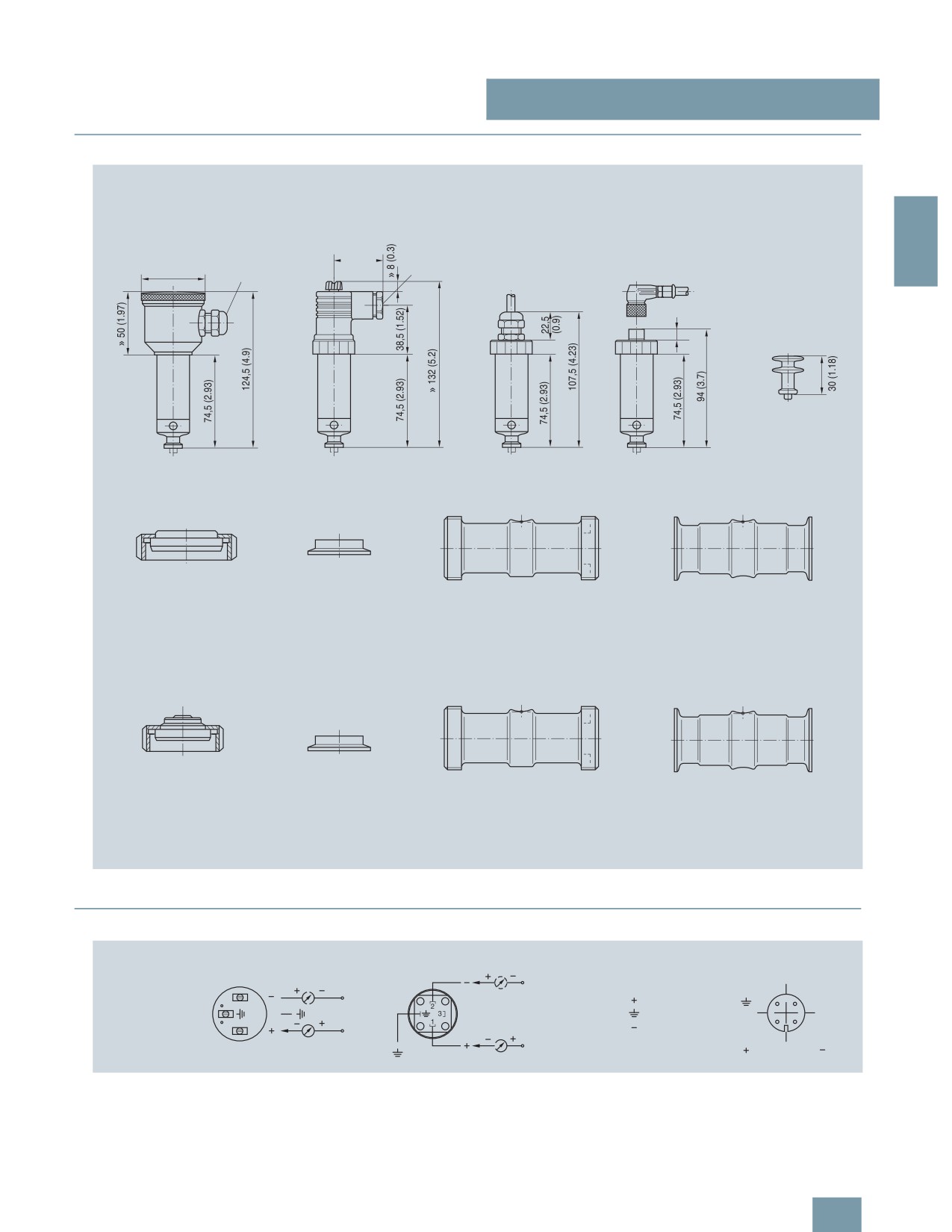
SITRANS P measuring instruments for pressure
Transmitters for food, pharmaceuticals and biotechnology
SITRANS P Compact
for gage and absolute pressure
■Dimensional drawings
B
!5
(
!
" F
!
5
* = 0% ?;
4
?:
,
*
4
?;
4
?;
$ F &
%
*
4
?;
2
?:
&
%< $ #;%%
B
F
!
1#
E;
B
F
!
1#
0 ###
$
#
7 ###
#%<%
$!
1#
#<:%
0#; ###
$
#
7 ###
#%<%
<$
#%;%
>5
1
!
4
1
D" $%< DB%
B
!
!
!
" 1
!
!
1
*=%
?:?
$4
!%
*=%
?:?
*=
7;
7;
! 5
!
*= ; ###
*= ; ### ?;
*= ; ### ?;
*=
7;
7;%
A ###
8A
*= ; ### ?;
A ###
8A
(
!
!
" 1
!
!$
%
1
! 5
!
=
1
$ C!1
$-
5
! 5
!
=
1
$ C!1
$-
5
=
1
$ C!1
$-
5
*= ; ### ;
*=
7?0
*= ; ### ?;
*=
7?0
A ### A
=
1
$ C!1
$-
5
A ### A
*= ; ### ?;
*= ; ### ?;
A ### A
A ### A
SITRANS P, dimensions in mm (inch)
■Schematics
'
(
*
+
G
)+
,
G
+
-
)G
+
(
)G
SITRANS P Compact, connection diagram
2/27
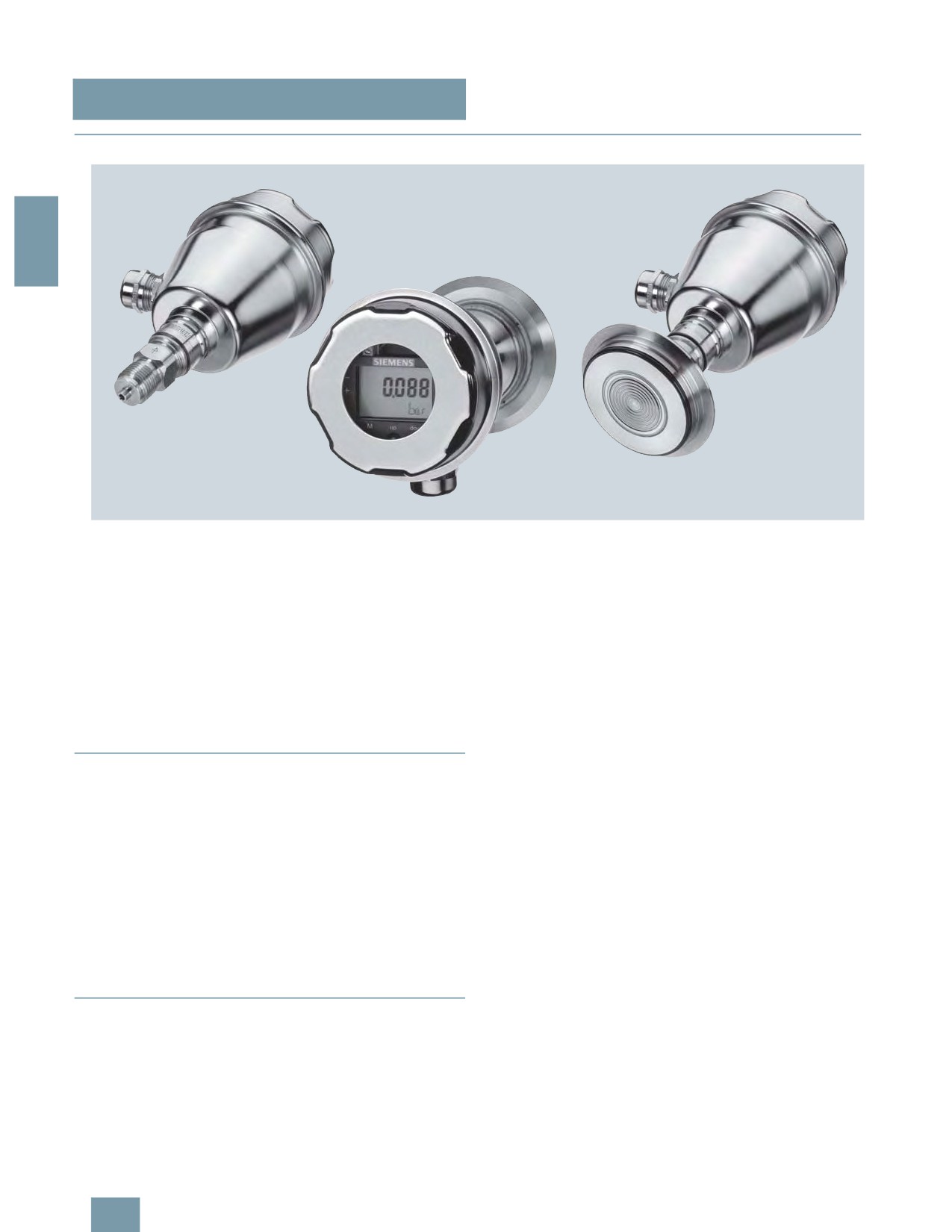
SITRANS P measuring instruments for pressure
Transmitters for food, pharmaceuticals and biotechnology
SITRANS P300 for gage and absolute pressure
■Overview
2
The SITRANS P300 is a digital pressure transmitter for gage and
It can be used for the following measurement types:
absolute pressure. All conventional thread versions are available
• Gage pressure
as process connections. In addition, various hygiene-based
• Absolute pressure
connections and flange connections with front-flush diaphragms
meet the requirements of a dead space free process connec-
With appropriate parameter settings, it can also be used for the
tion.
following additional measurement types:
The output signal is a load-independent direct current from 4 to
• Level
20 mA or a PROFIBUS PA signal, which is linearly proportional to
• Volume
the input pressure. Communication is over HART protocol or
• Mass
over PROFIBUS PA interface. Convenient buttons for easy local
operation of the basic settings of the pressure transmitter.
The "intrinsically-safe" EEx version of the transmitter can be in-
stalled in hazardous areas (zone 1). The transmitters are pro-
The SITRANS P300 has a single-chamber stainless steel casing.
vided with an EC type examination certificate and comply with
The pressure transmitter is approved with "intrinsically safe" type
the respective harmonized European standards of ATEX.
of protection It can be used in zone 1 or zone 0.
Gage pressure
■ Benefits
This variant measures aggressive, non-aggressive and hazard-
• High quality and long life
ous gases, vapors and liquids.
• High reliability even under extreme chemical and mechanical
The smallest measuring span is 10 mbar g, the largest 400 bar g.
loads
Level
• Extensive diagnosis and simulation functions
• Minimum conformity error
With appropriate parameter settings, the gage pressure variant
measures the level of aggressive, non-aggressive and hazard-
• Small long-term drift
ous liquids.
• Wetted parts made of high-grade materials (such as stainless
For measuring the level in an open container you require one de-
steel, Hastelloy)
vice; for measuring the level in a closed container, you require
• Measuring range 8 mbar to 400 bar
two devices and a process control system.
• High measuring accuracy
Absolute pressure
• Parameterization over control keys and HART communication
or PROFIBUS PA communication
This variant measures the absolute pressure of aggressive, non-
aggressive and hazardous gases, vapors and liquids.
■Application
The smallest measuring span is 8 mbar a, the largest 30 bar a.
The pressure transmitter is available in versions for gage pres-
sure and for absolute pressure. The output signal is always a
load-independent direct current from 4 to 20 mA or a
PROFIBUS PA signal, which is linearly proportional to the input
pressure. The pressure transmitter measures aggressive, non-
aggressive and hazardous gases, as well as vapors and liquids.
2/28
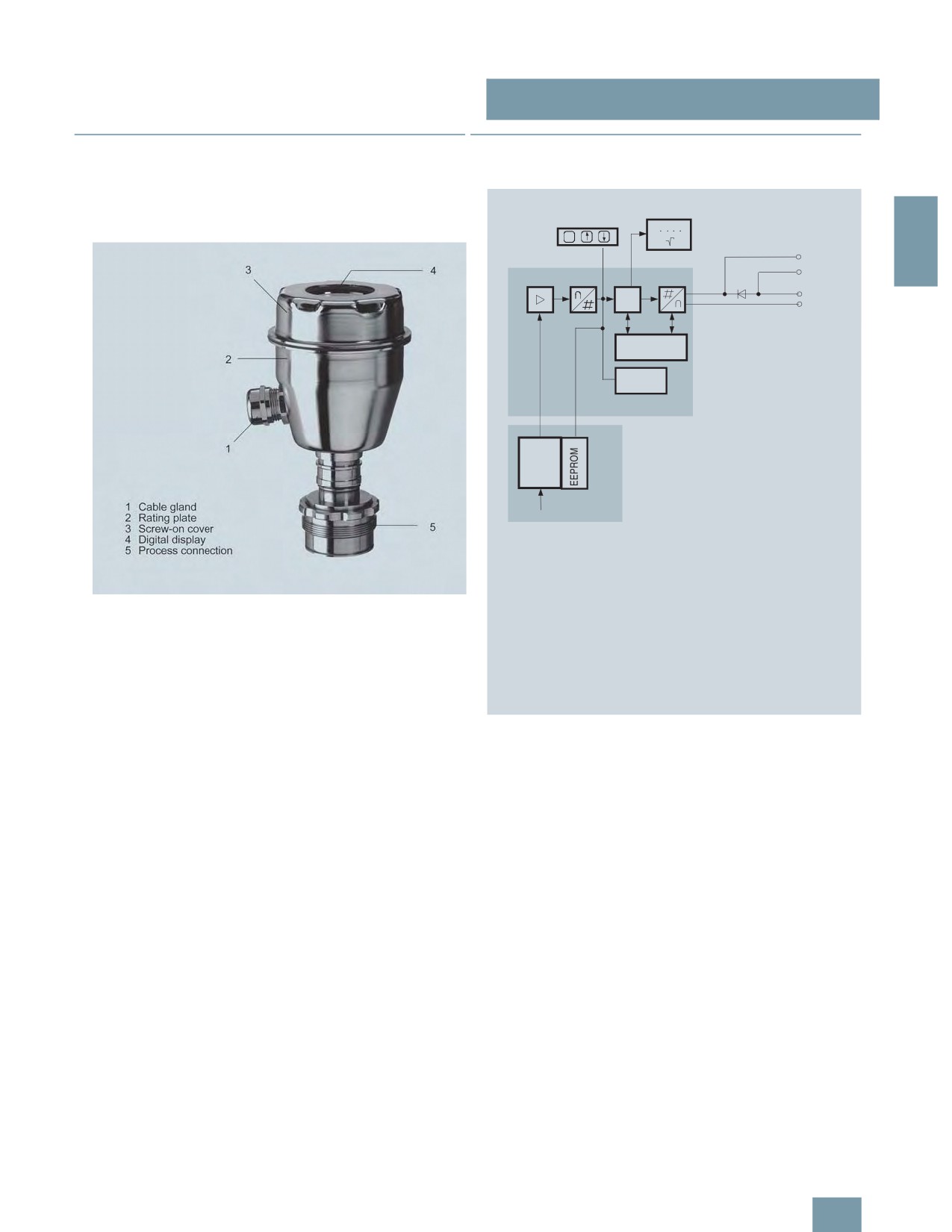
SITRANS P measuring instruments for pressure
Transmitters for food, pharmaceuticals and biotechnology
SITRANS P300 for gage and absolute pressure
■Design
■Function
The device comprises:
Operation of the electronics with HART communication
• Electronics
• Housing
• Measuring cell
2
,
"
($
2
2( >
4
++
,
+
,
,
1
1 4
%
(
!
&
0
,
;
&
?
&
11
5
5
1
!
Perspective view of the SITRANS P300
:
2( >
4
7
>5
3
$
%
The housing has a screw-on cover (3), with or without an inspec-
<
!
tion window depending on the version. The electrical terminal
* !
!
4
@
11
housing, the buttons for operation of the device and, depending
(
2
on the version, the digital display are located under this cover.
& F
The connections for the auxiliary power UH and the shield are in
the terminal housing. The cable gland is mounted on the side of
the housing. The measuring cell with the process connection (5)
is located on the underside of the housing. Depending on the
Function diagram of electronics
version of the device, the measuring cell with the process con-
nection may differ from the one shown in the diagram.
The input pressure is converted into an electrical signal by the
sensor (1). This signal is amplified by the measuring amplifier (2)
and digitalized in an analog to digital converter (3). The digital
signal is analyzed in a microcontroller (4) and corrected with re-
gard to linearity and thermal characteristics. In a digital to ana-
log converter (5) it is then converted into the output current of 4
to 20 mA. A diode circuit provides reverse voltage protection.
You can make an uninterrupted current measurement with a low-
ohm ammeter at the connection (10). The data specific to the
measuring cell, the electronic data and parameter settings are
stored in two non-volatile memories (6). The first memory is
linked with the measuring cell, the second with the electronics.
The buttons (8) can be used to call up individual functions, so-
called modes. If you have a device with a digital display (9), you
can use this to track mode settings and other messages. The ba-
sic mode settings can be changed with a computer via the HART
modem (7).
2/29

SITRANS P measuring instruments for pressure
Transmitters for food, pharmaceuticals and biotechnology
SITRANS P300 for gage and absolute pressure
Operation of the electronics with PROFIBUS PA communica-
Mode of operation of the FOUNDATION Fieldbus
tion
electronics
,
,
2
(
BB
"
"
4
4
!
!
++
,
++
,
"
"
+
+
,
,
,
,
7
>5
3
,
7
>5
3
1
1 4
$
%
1
1 4
$
%
%
(
!
&
<
!
%
(
!
&
<
*
!
0
,
0
,
;
+
* ) (
3
;
+
?
&
11
1
?
&
11
& F
5
5
1
5
5
1
!
& F
!
:
B
(
4
:
BB
4
Function diagram of electronics
Function diagram of electronics
The bridge output voltage created by the sensor (1, Figure
The input pressure is converted into an electrical signal by the
"Function diagram of electronics") is amplified by the instrument
sensor (1). This signal is amplified by the measuring amplifier (2)
amplifier (2) and digitized in the analog-to-digital converter (3).
and digitalized in an analog to digital converter (3). The digital
The digital information is evaluated in the microcontroller, its lin-
signal is analyzed in a microcontroller (4) and corrected with re-
earity and temperature response corrected, and provided on the
gard to linearity and thermal characteristics. It is then made
FOUNDATION Fieldbus through an electrically isolated
available at the PROFIBUS PA over an electrically isolated
FOUNDATION Fieldbus Interface (7).
PROFIBUS PA interface (7). The data specific to the measuring
cell, the electronic data and parameter settings are stored in two
The data specific to the measuring cell, the electronics data, and
non-volatile memories (6). The first memory is linked with the
the parameter data are stored in the two non-volatile memories
measuring cell, the second with the electronics.
(6). The one memory is coupled to the measuring cell, the other
to the electronics. As the result of this modular design, the elec-
The buttons (8) can be used to call up individual functions, so-
tronics and the measuring cell can be replaced separately from
called modes. If you have a device with a digital display (9), you
each other.
can use this to track mode settings and other messages. The ba-
sic mode settings can be changed with a computer over the bus
Using the three input keys (8) you can parameterize the pressure
master (12).
transmitter directly at the point of measurement. The input keys
can also be used to control the view of the results, the error mes-
sages and the operating modes on the digital display (9).
The results with status values and diagnostic values are trans-
ferred by cyclic data transmission on the FOUNDATION
Fieldbus. Parameterization data and error messages are trans-
ferred by acyclic data transmission. Special software such as
National Instruments Configurator is required for this.
Mode of operation of the measuring cells
The process connections available include the following:
• G½
• ½-14 NPT
• Front-flush diaphragm:
- Flanges to EN
- Flanges to ASME
- NuG and pharmaceutical connections
2/30
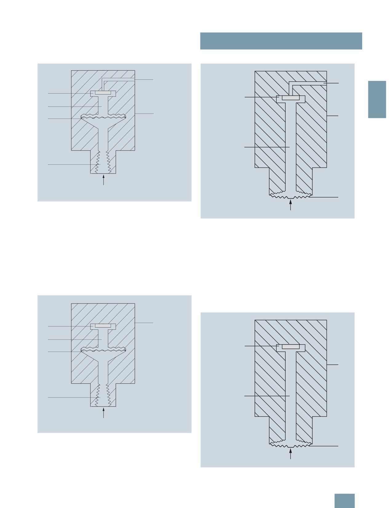
SITRANS P measuring instruments for pressure
Transmitters for food, pharmaceuticals and biotechnology
SITRANS P300 for gage and absolute pressure
Measuring cell for gage pressure
Measuring cell for gage pressure, front-flush diaphragm
1
1
6
2
5
5
2
2
4
4
1 Reference pressure
3
2 Measuring cell
3 Process connection
4 Seal diaphragm
1 Reference pressure
5 Filling liquid
2 Measuring cell
6 Relative pressure sensor
3 Seal diaphragm
p
e
pe Pressure as input variable
4 Filling liquid
5 Relative pressure sensor
3
pe Pressure as input variable
Measuring cell for gage pressure, function chart
SH
The input pressure (pe) is transferred to the gage pressure sen-
sor (6) via the seal diaphragm (4) and the filling liquid (5), dis-
Measuring cell for gage pressure, front-flush diaphragm, function chart
placing its measuring diaphragm. The displacement changes
the resistance value of the four piezo resistors in the measuring
The input pressure (pe) is transferred to the gage pressure sen-
diaphragm in a bridge circuit. The change in the resistance
sor (6) via the seal diaphragm (4) and the filling liquid (5), dis-
causes a bridge output voltage proportional to the input pres-
placing its measuring diaphragm. The displacement changes
sure.
the resistance value of the four piezo resistors in the measuring
diaphragm in a bridge circuit. The change in the resistance
The transmitters with spans ≤ 63 bar measure the input pressure
causes a bridge output voltage proportional to the input pres-
against atmosphere, those with spans ≥ 160 bar against
sure.
vacuum.
The transmitters with spans ≤ 63 bar measure the input pressure
against atmosphere, those with spans ≥ 160 bar against
Measuring cell for absolute pressure
vacuum.
Measuring cell for absolute pressure, front-flush diaphragm
1
5
4
4
3
1
2
1 Measuring cell
3
2 Process connection
3 Seal diaphragm
4 Filling liquid
5 Absolute pressure sensor
pe
pe Pressure as input variable
1 Measuring cell
2 Seal diaphragm
Measuring cell for absolute pressure, function chart
3 Filling liquid
4 Absolute pressure sensor
2
The input pressure (pe) is transferred to the absolute pressure
pe Pressure as input variable
sensor (5) via the seal diaphragm (3) and the filling liquid (4),
displacing its measuring diaphragm. The displacement
SH
changes the resistance value of the four piezo resistors in the
measuring diaphragm in a bridge circuit. The change in the re-
Measuring cell for absolute pressure, front-flush diaphragm, function
sistance causes a bridge output voltage proportional to the input
chart
pressure.
2/31

SITRANS P measuring instruments for pressure
Transmitters for food, pharmaceuticals and biotechnology
SITRANS P300 for gage and absolute pressure
The input pressure (pe) is transferred to the absolute pressure
Adjustable parameters on SITRANS P300 with HART communi-
sensor (5) via the seal diaphragm (3) and the filling liquid (4),
cation
displacing its measuring diaphragm. The displacement
Parameters
Input keys
HART com-
changes the resistance value of the four piezo resistors in the
munication
measuring diaphragm in a bridge circuit. The change in the re-
sistance causes a bridge output voltage proportional to the input
Start of scale
x
x
pressure.
Full-scale value
x
x
2
Parameterization of SITRANS P300
Electrical damping
x
x
Depending on the version, there are a range of options for pa-
Start-of-scale value without application
x
x
of a pressure ("Blind setting")
rameterizing the pressure transmitter and for setting or scanning
the parameters.
Full-scale value without application of a
x
x
pressure ("Blind setting")
Parameterization using the input keys (local operation)
Zero adjustment
x
x
With the input keys you can easily set the most important param-
Current transmitter
x
x
eters without any additional equipment.
Fault current
x
x
Parameterization using HART communication
1)
Disabling of keys, write protection
x
x
Parameterization using HART communication is performed with
a HART communicator or a PC.
Type of dimension and actual dimension x
x
Input of characteristic
x
Freely-programmable LCD
x
Diagnostics functions
x
> (=
%
###
1) Cancel apart from write protection
1
Diagnostic functions for SITRANS P300 with HART communica-
2( >
tion
11
• Zero correction display
• Event counter
Communication between a HART communicator and a pressure transmit-
• Limit transmitter
ter
• Saturation alarm
When parameterizing with the HART communicator, the connec-
• Slave pointer
tion is made directly to the 2-wire system.
• Simulation functions
• Maintenance timer
Available physical units of display for SITRANS P300 with HART
communication
> (=
%
### ;
1
Physical variable
Physical dimensions
"
Pressure (setting can also be made
Pa, MPa, kPa, bar, mbar, torr, atm,
2( >
in the factory)
psi, g/cm2, kg/cm2, inH2O, inH2O
1 ! 1
(4 °C), mmH2O, ftH2O (20 °C),
inHg, mmHg
%
Level (height data)
m, cm, mm, ft, in
Volume
m3, dm3, hl, yd3, ft3, in3, US gal-
lon, lmp. gallon, bushel, barrel,
HART communication between a PC communicator and a pressure
barrel liquid
transmitter
Mass
g, kg, t, lb, Ston, Lton, oz
When parameterizing with a PC, the connection is made through
a HART modem.
Temperature
K, °C, °F, °R
Miscellaneous
%, mA
The signals needed for communication in conformity with the
HART 5.x or 6.x protocols are superimposed on the output cur-
rent using the Frequency Shift Keying (FSK) method.
2/32

SITRANS P measuring instruments for pressure
Transmitters for food, pharmaceuticals and biotechnology
SITRANS P300 for gage and absolute pressure
Parameterization through PROFIBUS PA interface
Hygiene version
Fully digital communication through PROFIBUS PA, profile 3.0, is
In the case of the SITRANS P300 with 7MF812.-... front-flush di-
particularly user-friendly. The PROFIBUS puts the DS III PA is in
aphragm, selected connections comply with the requirements of
connection with a process control system, e.g. SIMATIC PSC 7.
the EHEDG or 3A. You will find further details in the order form.
Communication is possible even in a potentially explosive envi-
Please note in particular that the seal materials used must com-
ronment.
ply with the requirements of 3A. Similarly, the filling liquids used
must be FDA-compliant.
2
For parameterization through PROFIBUS you need suitable soft-
ware, e.g. SIMATIC PDM (Process Device Manager).
Parameterization through FOUNDATION Fieldbus Interface
Fully digital communication through FOUNDATION Fieldbus is
particularly user-friendly. Through the FOUNDATION Fieldbus
the P300 FF is connected to a process control system. Commu-
nication is possible even in a potentially explosive environment.
For parameterization through the FOUNDATION Fieldbus you
need suitable software, e.g. National Instruments Configurator.
Adjustable parameters for P300 PA and FF
Parameters
Input keys
PROFIBUS PA and
(DS III HART) FOUNDATION
Fieldbus interface
Electrical damping
x
x
Zero adjustment (correction of
x
x
position)
Key and/or function disabling x
x
Source of measured-value dis-
x
x
play
Physical dimension of display x
x
Position of decimal point
x
x
Bus address
x
x
Adjustment of characteristic
x
x
Input of characteristic
x
Freely-programmable LCD
x
Diagnostics functions
x
Diagnostic functions for P300 PA and FF
• Event counter
• Slave pointer
• Maintenance timer
• Simulation functions
• Display of zero correction
• Limit transmitter
• Saturation alarm
Physical dimensions available for the display
Physical variable
Physical dimensions
Pressure (setting can also MPa, kPa, Pa, bar, mbar, torr, atm, psi,
be made in the factory)
g/cm2, kg/cm2, mmH2O, mmH2O (4 °C),
inH2O, inH20 (4 °C), ftH2O (20 °C), mmHg,
inHg
Level (height data)
m, cm, mm, ft, in, yd
Volume
m3, dm3, hl, yd3, ft3, in3, US gallon, lmp.
gallon, bushel, barrel, barrel liquid
Volume flow
m3/s, m3/min, m3/h, m3/d, l/s, l/min, l/h, l/
d, Ml/d, ft3/s, ft3/min, ft3/h, ft3/d, US gal-
lon/s, US gallon/min, US gallon/h, US gal-
lon/d, bbl/s, bbl/min, bbl/h, bbl/d
Mass flow
g/s, g/min, g/h, g/d, kg/s, kg/min, kg/h,
kg/d, t/s, t/min, t/h, /t/d, lb/s, lb/min, lb/h,
lb/d, STon/s, STon/min, STon/h, STon/d,
LTon/s, LTon/min, LTon/h, LTon/d
Total mass flow
t, kg, g, lb, oz, LTon, STon
Temperature
K, °C, °F, °R
Miscellaneous
%
2/33

SITRANS P measuring instruments for pressure
Transmitters for food, pharmaceuticals and biotechnology
SITRANS P300 for gage and absolute pressure
■ Technical specifications
F
SITRANS P300 for gage pressure and absolute pressure
HART
PROFIBUS PA and FOUNDATION Fieldbus
Gage pressure input
2
Measured variable
Gage pressure
Spans (infinitely adjustable) or
Span
Max. perm. test pres-
Nominal measuring
Max. perm. test pres-
nominal measuring range and
sure
range
sure
max. pemissible test pressure
0.01 ... 1 bar g
6 bar g
1 bar g
6 bar g
(0.15 ... 14.5 psi g)
(87 psi g)
(14.5 psi g)
(87 psi g)
0.04 ... 4 bar g
10 bar g
4 bar g
10 bar g
(0.58 ... 58 psi g)
(145 psi g)
(58 psi g)
(145 psi g)
0.16 ... 16 bar g
32 bar g
16 bar g
32 bar g
(2.3 ... 232 psi g)
(464 psi g)
(232 psi g)
(464 psi g)
0.6 ... 63 bar g
100 bar g
63 bar g
100 bar g
(9.1 ... 914 psi g)
(1450 psi g)
(914 psi g)
(1450 psi g)
1.6 ... 160 bar g
250 bar g
160 bar g
250 bar g
(23.2 ... 2321 psi g)
(3626 psi g)
(2321 psi g)
(3626 psi g)
4.0 ... 400 bar g
600 bar g
400 bar g
600 bar g
(58 ... 5802 psi g)
(8700 psi g)
(5802 psi g)
(8700 psi g)
Depending on the process connection, the span
Depending on the process connection, the nomi-
may differ from these values
nal measuring range may differ from these values
Lower measuring limit
• Measuring cell with silicone oil
30 mbar a (0.44 psi a)
Upper measuring limit
• Measuring cell with silicone oil
100% of max. span
100% of the max. nominal measuring range
Absolute pressure input
Measured variable
Absolute pressure
Spans (infinitely adjustable) or
Span
Max. perm. test pres-
Nominal measuring
Max. perm. test pres-
nominal measuring range and
sure
range
sure
max. pemissible test pressure
8 ... 250 mbar a
6 bar a
250 mbar a
6 bar a
(0.12 ... 3.6 psi a)
(87 psi a)
(3.6 psi a)
(87 psi a)
0.043 ... 1.30 bar a
10 bar a
1.30 bar a
10 bar a
(0.62 ... 19 psi a)
(145 psi a)
(19 psi a)
(145 psi a)
0.16 ... 5 bar a
30 bar a
5 bar a
30 bar a
(2.3 ... 73 psi a)
(435 psi a)
(73 psi a)
(435 psi a)
1 ... 30 bar a
100 bar a
30 bar a
100 bar a
(14.5 ... 435 psi a)
(1450 psi a)
(435 psi a)
(1450 psi a)
Lower measuring limit
• Measuring cell with silicone oil
0 mbar a (0 psi a)
Upper measuring limit
• Measuring cell with silicone oil
100% of max. span
100% of the max. nominal measuring range
Input of gage pressure, with front-flush diaphragm
Measured variable
Gage pressure, front-flush
Spans (infinitely adjustable) or
Span
Max. perm. test pres-
Nominal measuring
Max. perm. test pres-
nominal measuring range and
sure
range
sure
max. pemissible test pressure
0.01 ... 1 bar g
6 bar g
1 bar g
6 bar g
(0.145 ... 14.5 psi g)
(87 psi g)
(14.5 psi g)
(87 psi g)
0.04 ... 4 bar g
10 bar g
4 bar g
10 bar g
(0.58 ... 58 psi g)
(145 psi g)
(58 psi g)
(145 psi g)
0.16 ... 16 bar g
32 bar g
16 bar g
32 bar g
(2.32 ... 232 psi g)
(464 psi g)
(232 psi g)
(464 psi g)
0.6 ... 63 bar g
100 bar g
63 bar g
100 bar g
(9.14 ... 914 psi g)
(1450 psi g)
(914 psi g)
(1450 psi g)
Lower measuring limit
-100 mbar g (-1.45 psi g)
Upper measuring limit
• Measuring cell with silicone oil
100% of max. span
100% of the max. nominal measuring range
2/34

SITRANS P measuring instruments for pressure
Transmitters for food, pharmaceuticals and biotechnology
SITRANS P300 for gage and absolute pressure
SITRANS P300 for gage pressure and absolute pressure
HART
PROFIBUS PA and FOUNDATION Fieldbus
Input of absolute pressure, with front-flush diaphragm
Measured variable
Absolute pressure (front-flush)
Spans (infinitely adjustable) or
Span
Max. perm. test pres-
Nominal measuring
Max. perm. test pres-
nominal measuring range and
sure
range
sure
2
max. pemissible test pressure
43 ... 1300 mbar a
10 bar a
1300 mbar a
10 bar a
(0.62 ... 18.9 psi a)
(145 psi a)
(18.9 psi a)
(145 psi a)
0.16 ... 5 bar a
30 bar a
5 bar a
30 bar a
(2.32 ... 72.5 psi a)
(435 psi a)
(72,5 psi a)
(435 psi a)
1 ... 30 bar a
100 bar a
30 bar a
100 bar a
(14.5 ... 435 psi a)
(1450 psi a)
(435 psi a)
(1450 psi a)
Depending on the process connection, the span
Depending on the process connection, the nomi-
may differ from these values
nal measuring range may differ from these values
Lower measuring limit
0 bar a (0 psi a)
Upper measuring limit
• Measuring cell with silicone oil
100% der max. Messspanne
100% des max. Nennmessbereichs
Output
Output signal
4 ... 20 mA
Digital PROFIBUS PA signal
Physical bus
-
IEC 61158-2
With polarity reversal protection
No
Yes
Electrical damping T63 (step width 0.1 s)
Set to 0.1 s (0 ... 100 s)
Accuracy
To EN 60770-1
Reference conditions
Increasing characteristic, start-of-scale value 0 bar, stainless steel seal diaphragm, measuring cell
(All error data refer always refer to the set
with silicone oil, room temperature 25 °C (77 °F), span ratio (r = max. span / set span)
span)
Measurement deviation with cut-off point set-
ting, including hysteresis and repeatability.
Gage pressure
Absolute
(Absolute
Gage pressure
Absolute
(Absolute
pressure
pressure,
pressure
pressure,
front-
front-
flushed)
flushed)
Linear characteristic curve
≤ 0,075%
≤ 0,1%
≤ 0,2%
• r ≤ 10
≤ (0.0029 ⋅ r + 0.071)%
≤ 0,1%
≤ 0,2%
• 10 < r ≤ 30
≤ (0.0045 ⋅ r + 0.071)%
≤ 0,2%
≤ 0,4%
• 30 < r ≤ 100
≤ (0.005 ⋅ r + 0.05)%
-
-
Settling time T63 without electrical damping
Approx. 0.2 s
Long-term drift at ± 30 °C (± 54 °F)
≤ (0.25 ⋅ r)%/5 years
≤ (0.1 ⋅ r)%/year
≤ 0.25%/5 years
≤ 0.1%/year
Influence of ambient temperature
• at -10 ... +60 °C (14 ... 140 °F)
≤ (0.1 ⋅ r +0.2)%
≤ (0.2 ⋅ r
≤ 0,3%
≤ 0,5%
+0.3)%
• at -40 ... -10 °C and +60 ... +85 °C
≤ (0.1 ⋅ r + 0.15)% / 10 K
≤ (0.2 ⋅ r +
≤ 0.25%/10 K
≤ 0.5%/
(-40 ... 14 °F and 140 ... 185 °F)
0.3)%/10 K
10 K
Influence of the medium temperature (only
with front-flush diaphragm)
• Temperature difference between medium
3 mbar/10 K (0.04 psi/10 K)
temperature and ambient temperature
2/35
SITRANS P measuring instruments for pressure
Transmitters for food, pharmaceuticals and biotechnology
SITRANS P300 for gage and absolute pressure
SITRANS P300 for gage pressure and absolute pressure
HART
PROFIBUS PA and FOUNDATION Fieldbus
Rated operating conditions
Installation conditions
Ambient temperature
Observe the temperature class in areas subject to explosion hazard.
2
• Measuring cell with silicone oil
-40 ... +85 °C (-40 ... +185 °F)
• Measuring cell with Neobee oil (with front-
-10 ... +85 °C (14 ... +185 °F)
flush diaphragm)
• Measuring cell with inert liquid (not with
-20 ... +85 °C (-4 ... +185 °F)
front-flush diaphragm)
• Digital display
-30 ... +85 °C (-22 ... +185 °F)
• Storage temperature
-50 ... +85 °C (-58 ... +185 °F)
(with Neobee: -20 ... +85 °C (-4 ... +185 °F)
Climatic class
Condensation
Permissible
Degree of protection to EN 60529
IP65, IP68, NEMA X, enclosure cleaning, resistant to lyes, steam to 150° C (302 °F)
Electromagnetic compatibility
• Emitted interference and interference immunity
To EN 61326 and NAMUR NE 21
Medium conditions
Process temperature
• Measuring cell with silicone oil
-40 ... +100 °C (-40 ... +212 °F)
• Measuring cell with silicone oil (with front-
-40 ... +150 °C (-40 ... +302 °F)
flush diaphragm)
• Measuring cell with Neobee oil (with front-
-40 ... +150 °C (-40 ... +302 °F)
flush diaphragm)
• Measuring cell with silicone oil, with temper-
-40 ... +200 °C (-40 ... +392 °F)
ature isolator (only with front-flush dia-
phragm)
• Measuring cell with inert liquid
-20 ... +100 °C (-4 ... +212 °F)
• Measuring cell with high temperature oil
-10 ... +250 °C (14 ... +482 °F)
Design (standard version)
Weight (without options)
Approx. 800 g (1.8 lb)
Housing material
Stainless steel, mat. No. 1.4301/304
Material of parts in contact with the medium
• Connection shank
Stainless steel, mat. No. 1.4404/316L or Hastelloy C276, mat. No. 2.4819
• Oval flange
Stainless steel, mat. No. 1.4404/316L
• Seal diaphragm
Stainless steel, mat. No. 1.4404/316L or Hastelloy C276, mat. No. 2.4819
• Measuring cell filling
• Silicone oil
• Inert filling liquid
Process connection
• G½B to DIN EN 837-1
• Female thread ½-14 NPT
• Oval flange PN 160 (MWP 2320 psi) with fastening thread:
-
7/16-20 UNF to IEC 61518
- M10 as per DIN 19213
Design (version with front-flush dia-
phragm)
Weight (without options)
Approx. 1 ... 13 kg (2.2 ... 29 lb)
Housing material
Stainless steel, mat. No. 1.4301/304
Material of parts in contact with the medium
• Process connection
Stainless steel, mat. No. 1.4404/316L
• Seal diaphragm
Stainless steel, mat. No. 1.4404/316L
• Measuring cell filling
• Silicone oil
• Inert filling liquid
• FDA compliant fill fluid (Neobee oil)
Process connection
• Flanges as per EN and ASME
• F&B and pharmaceutical flanges
2/36

SITRANS P measuring instruments for pressure
Transmitters for food, pharmaceuticals and biotechnology
SITRANS P300 for gage and absolute pressure
SITRANS P300 for gage pressure and absolute pressure
HART
PROFIBUS PA and FOUNDATION Fieldbus
Power supply UH
Terminal voltage on transmitter
10.5 ... 42 V DC
Supplied through bus
for intrinsically safe operation: 10.5 ... 30 V DC
Separate power supply
-
Not necessary
2
Bus voltage
• Without EEx
-
9 ... 32 V
• For intrinsically-safe operation
-
9 ... 24 V
Current consumption
• Max. basic current
-
12.5 mA
• Startup current ≤ basic current
-
Yes
• Max. fault current in the event of a fault
-
15.5 mA
Fault disconnection electronics (FDE)
-
Available
Certificate and approvals
Classification according to pressure equip-
For gases of fluid group 1 and liquids of fluid group 1; complies with requirements of Article 3, para-
ment directive (DRGL 97/23/EC)
graph 3 (sound engineering practice)
Water, waste water
Available soon
Explosion protection
Intrinsic safety "i"
PTB 05 ATEX 2048
Identification
Ex II 1/2 G EEx ia/ib IIB/IIC T4, T5, T6
Permissible ambient temperature
• Temperature class T4
-40 ... +85 °C (-40 ... +185 °F)
• Temperature class T5
-40 ... +70 °C (-40 ... +158 °F)
• Temperature class T6
-40 ... +60 °C (-40 ... +140 °F)
Connection
To certified intrinsically-safe circuits with maxi-
To certified intrinsically-safe circuits with maxi-
mum values:
mum values:
Ui = 30 V, Ii = 100 mA,
FISCO supply unit:
Pi = 750 mW, Ri = 300 Ω
Ui = 17.5 V, Ii = 380 mA, Pi = 5.32 W
Linear barrier:
Ui = 24 V, Ii = 250 mA, Pi = 1.2 W
Effective inner capacitance:
Ci = 6 nF
Ci = 1.1 nF
Effective inner inductance:
Li = 0.4 mH
Li ≤ 7 μH
Explosion protection to FM for USA and
Canada (cFMUS)
• Identification (DIP) or (IS); (NI)
Certificate of Compliance 3025099
CL I, DIV 1, GP ABCD T4 ... T6; CL II, DIV 1, GP EFG; CL III; CL I, ZN 0/1 AEx ia IIC T4 ... T6;
CL I, DIV 2, GP ABCD T4 ... T6; CL II, DIV 2, GP FG; CL III
• Identification (DIP) or (IS)
Certificate of Compliance 3025099C
CL I, DIV 1, GP ABCD T4 ... T6; CL II, DIV 1, GP EFG; CL III; Ex ia IIC 4 ... T6;
CL I, DIV 2, GP ABCD T4 ... T6; CL II, DIV 2, GP FG; CL III
2/37

SITRANS P measuring instruments for pressure
Transmitters for food, pharmaceuticals and biotechnology
SITRANS P300 for gage and absolute pressure
HART communication
Communication FOUNDATION Fieldbus
HART communication
230 ... 1100 Ω
Function blocks
3 function blocks analog input,
1 function block PID
Protocol
HART Version 5.x
• Analog input
Software for computer
SIMATIC PDM
- Adaptation to customer-specif-
Yes, linearly rising or falling char-
2
ic process variables
acteristic
PROFIBUS PA communication
- Electrical damping T63 , adjust-
0 ... 100 s
Simultaneous communication with
4
able
master class 2 (max.)
- Simulation function
Output/input (can be locked within
The address can be set using
Configuration tool or local opera-
the device with a bridge)
tion (standard setting address
126)
- Failure mode
Can be parameterized (last good
value, substitute value, incorrect
Cyclic data usage
value)
• Output byte
5 (one measuring value) or
- Limit monitoring
Yes, one upper and lower warning
10 (two measuring values)
limit and one alarm limit respec-
• Input byte
0, 1, or 2 (register operating mode
tively
and reset function for metering)
- Square-rooted characteristic
Yes
Internal preprocessing
for flow measurement
Device profile
PROFIBUS PA Profile for Process
• PID
Standard FF function block
Control Devices Version 3.0,
• Physical block
1 Resource block
Class B
Transducer blocks
1 transducer block Pressure with
Function blocks
2
calibration, 1 transducer block
• Analog input
LCD
- Adaptation to customer-specif-
Yes, linearly rising or falling char-
• Pressure transducer block
ic process variables
acteristic
-
Can be calibrated by applying
Yes
- Electrical damping T63 , adjust-
0 ... 100 s
two pressures
able
-
Monitoring of sensor limits
Yes
- Simulation function
Input /Output
-
Simulation function: Measured
Constant value or over parameter-
- Failure mode
Can be parameterized (last good
pressure value, sensor temper-
izable ramp function
value, substitute value, incorrect
ature and electronics tempera-
value)
ture
- Limit monitoring
Yes, one upper and lower warning
limit and one alarm limit respec-
tively
• Register (totalizer)
Can be reset, preset, optional
direction of counting, simulation
function of register output
- Failure mode
Can be parameterized (summation
with last good value, continuous
summation, summation with incor-
rect value)
- Limit monitoring
One upper and lower warning limit
and one alarm limit respectively
• Physical block
1
Transducer blocks
2
• Pressure transducer block
- Can be calibrated by applying
Yes
two pressures
- Monitoring of sensor limits
Yes
- Specification of a container
Max. 30 nodes
characteristic with
- Square-rooted characteristic
Yes
for flow measurement
- Gradual volume suppression
Parameterizable
and implementation point of
square-root extraction
- Simulation function for mea-
Constant value or over parameter-
sured pressure value and sen-
izable ramp function
sor temperature
2/38

SITRANS P measuring instruments for pressure
Transmitters for food, pharmaceuticals and biotechnology
SITRANS P300 for gage and absolute pressure
Selection and Ordering data
Order No.
Selection and Ordering data
Order No.
SITRANS P300 pressure transmitters for gage
SITRANS P300 pressure transmitters for gage
and absolute pressure, single-chamber measur-
and absolute pressure, single-chamber measur-
ing housing, rating plate inscription in English
ing housing, rating plate inscription in English
4 ... 20 mA/HART
7MF8023 -
4 ... 20 mA/HART
7MF8023 -
PROFIBUS PA
7MF8024 -
PROFIBUS PA
7MF8024 -
2
FOUNDATION Fieldbus (FF)
7MF8025 -
FOUNDATION Fieldbus (FF)
7MF8025 -
77777-
7777
77777-7777
Measuring cell filling Measuring cell cleaning
Display
Silicone oil
Standard
1
• Without display, with keys, closed lid5)
1
Inert liquid
Cleanliness level 2 to
3
• With display and keys, closed lid
2
DIN 25410
• With display and keys, lid with macrolon washer
4
(setting on HART devices: mA,
max. span
on PROFIBUS PA and FOUNDATION Fieldbus
0.01 ... 1 bar g
(0.145 ... 14.5 psi g)
B
devices: pressure units)
0.04 ... 4 bar g
(0.58 ... 58 psi g)
C
• With display (setting acc. to specifications, Order
5
0.16 ...16 bar g
(2.32 ... 232 psi g)
D
code "Y21" or "Y22" required), lid with macrolon
0.63 ... 63 bar g
(9.14 ... 914 psi g)
E
washer
1.6 ... 160 bar g
(23.2 ... 2320 psi g)
F
• With display and keys, lid with glass pane
6
4 ... 400 bar g
(58 ... 5800 psi g)
G
(setting on HART devices: mA, on PROFIBUS and
FOUNDATION Fieldbus devices: pressure units)
2.5 ... 25 mbar a
(0.036 ... 3.63 psi a)
F)
Q
13 ... 1300 mbar a
(0.19 ... 18.9 psi a)
F)
S
• With display (setting acc. to specifications, Order
7
0.05 ... 5 bar a
(0.7 ... 72.5 psi a)
F)
T
code "Y21" or "Y22" required), lid with glass pane
0.3 ... 30 bar a
(4.35 ... 435 psi a)
F)
U
Power supply units see "SITRANS I power supply units and isol. amplifiers".
Wetted parts materials
Factory-mounting of shut-off valves and valve manifolds see page
Seal diaphragm
Measuring cell
2/142.
Stainless steel
Stainless steel
A
Included in delivery of the device:
Hastelloy
Stainless steel
F)
B
• Brief instructions (Leporello)
• CD-ROM with detailed documentation
Hastelloy
Hastelloy
F)
C
Version for diaphragm seal 1) 2)
Y
1) When the manufacture’s certificate M (calibration certificate) has to be
ordered for transmitters with diaphragm seals, it is recommended only to
Process connection
order this certificate exclusively with the diaphragm seals. The measuring
• G½B to EN 837-1
0
accuracy of the total combination is certified here.
• ½-14 NPT
1
2) Whe the acceptance test certificate 3.1 for transmitters with direct-con-
nected diaphragm seals is ordered, this certificate must also be ordered
• Oval flange made of stainless steel
with the corresponding seals.
- Mounting thread 7/16-20 UNF to EN 61518
2
3) Can only be ordered in conjunction with electrical connection Option A.
- Mounting thread M10 to DIN 19213
3
4) Can only be ordered in conjunction with electrical connection Option B, C,
- Mounting thread M12 to DIN 19213
4
F or G.
5) Only together with HART electronics.
• Male thread M20 x 1,5
5
6) Without cable gland.
• Male thread ½ -14 NPT
6
F)
Subject to export regulations AL: 9I999, ECCN: N.
Non-wetted parts materials
• St. steel, deep-drawn and electrolytically polished
4
Version
• Standard version
1
Explosion protection
• Without
A
• With ATEX, Type of protection:
- "Intrinsic safety (EEx ia)"
B
• Zone 20/21/223)
C
• Ex nA/nL (zone 2)4)
E
• With FM „Intrinsic safe“ (cFMUS)
M
Electrical connection / cable entry
• Screwed gland M20x1.5 (Polyamide) 5)
A
• Screwed gland M20x1.5 (metal)
B
• Screwed gland M20x1.5 (stainless steel)
C
• M12 connector (metal, without cable socket)
F
• M12 connector (stainless steel, without cable socket)
G
• ½-14 NPT thread, metal 6)
H
• ½-14 NPT thread, stainless steel6)
J
2/39