Siemens SITRANS P. Operating Instructions (2019) - page 5
Functional Safety
10.1 Safety concept
See also
10.1.3
Safety function
The safety function of the device is the pressure measurement or the measurement of certain
process values which can be calculated from the pressure value.
The 4 to 20 mA analog output can be used as part of a safety instrumented function (SIF).
Ensure that you have only connected one device per channel and that the current output is
activated.
Besides the application-specific measuring errors under default reference conditions, an
additional safety accuracy of ± 2% of the maximum measuring range must be added:
Total tolerance (safety function) = ± [application-specific measurement error + 2 % safety
accuracy].
Example
A silo is to be securely monitored to check that the level does not exceed 10 meters.
Application-specific measurement error: 0.1%
Safety accuracy: 2.0%
Total tolerance: 2.1%
2.1% of 10 meters is 21 centimeters. When process monitoring is set to 9.79 meters, safe
shutdown is guaranteed even in the event of a random individual error within the safety
accuracy.
Note
Use of remote seals
If remote seals are used, the application-specific measurement error is the product of the
pressure transmitter and remote seal measurement errors.
Safety allowance
The diagnostics function reacts within 2 seconds after detection of an error.
Note
For use outside the standard reference conditions, contact Siemens to define an additional
safety accuracy.
See also
Remote seals and primary element for devices with functional safety (Page 41)
SITRANS P320/P420 with 4 to 20 mA/HART
160

Functional Safety
10.1 Safety concept
Safety-instrumented system in single-channel operation (SIL 2)
Transmitter
Automation system
Final controlling
P$
P$
Figure 10-1
Safety-instrumented system in single-channel operation
The combination of pressure transmitter, automation system and final controlling element
forms a safety-instrumented system that performs fail-safe behavior. The focus of this
description is on the pressure transmitter. For information on requirements for the automation
system or final controlling element, please refer to the corresponding standards.
The pressure transmitter generates a process-related measured value that is transferred to the
automation system. The automation system monitors this measured value. If the measured
value violates the high or low limit, the automation system generates a shutdown signal for the
connected final controlling element, which switches the corresponding valve to the specified
safety position.
Only one SITRANS P device is required for single-channel operation for SIL 2.
Safety-instrumented system in multi-channel operation (SIL 3)
Transmitter
Automation system
Final controlling elements
P$
P$
Figure 10-2
Safety-instrumented system in multi-channel operation
The combination of transmitter, automation system and final controlling element forms a safety-
instrumented system that performs a safety function. The emphasis of this description is on the
transmitter. For information on requirements for the automation system or final controlling
element, please refer to the corresponding standards.
The transmitter generates process-related measured values that are transferred to the
automation system. The automation system monitors these measured values. In the event of
a fault, the automation system generates shutdown signals for connected final controlling
elements that set the associated valve to the defined safety position. Faults are:
● Violations of the preset high or low limits
● Deviations between the two measured values
The automation system program must monitor the measured values of both SITRANS
P devices. As soon as the measured values differ by e.g. 2% or more, the system must be
brought into the safe state and the fault must be located.
SITRANS P320/P420 with 4 to 20 mA/HART
161

Functional Safety
10.1 Safety concept
Two SITRANS P devices are required for multi-channel operation for SIL 3. Operation with one
device is not permitted.
Note
Switching-off of system at high monitoring accuracy
The two transmitters are connected to the process at different positions. Actual differences in
pressure ≥ the total tolerance (safety function) can occur when the process is started up or if
there are other pressure variations. A difference in pressure ≥ the total tolerance (safety
function) will shut down the system.
● Match the monitoring accuracy of the automation system to the process.
● Mount the two transmitters exposed to equal conditions.
10.1.3.1
Device states
The following table provides a definition of the states of the device:
Device state
Description
Error class
Normal mode (4-20 mA)
The safe current output outputs
-
the measured value within the
defined safety accuracy.
Detected failure (safe state)
The safe current output is
(λDD) Rate of dangerous detec-
ted errors
≤ 3.6 mA or > 21.5 mA (specified
as failure signal).
Dangerous state
A dangerous state exists when a
(λDU) Rate of dangerous undetec-
current output is in the range
ted errors
4-20 mA and deviates from the
correct process value by more
than the specified safety accura-
cy (Page 160) for more than 2
seconds.
10.1.3.2
Safety characteristic values
You can find the safety characteristic values in the SIL Declaration of Conformity.
Note
Useful lifetime
Constant failure rates are assumed for the calculation of PFD/SFF. This assumption is valid for
environmental conditions that are typical for an industrial environment, corresponding to IEC
60654-1 class C (weatherproof locations) with an average long-term temperature of 40°C. After
14 years, however, the failure rates may increase.
SITRANS P320/P420 with 4 to 20 mA/HART
162

Functional Safety
10.1 Safety concept
10.1.4
Operating modes of the device
The device can be operated as follows:
● "Functional Safety disabled" is used for operation in non-safety-related applications.
● "Functional Safety enabled" is used for operation in safety-related applications.
See also
Enabling Functional Safety (Page 166)
10.1.5
Device mode
When Functional Safety is disabled, the following device modes are displayed via the display
or remote operation:
Device mode
Display
Description
Current output val-
Safe current output
ue
Functional Safety
STD
Used for operation
Operating signal
No
disabled
in non-safety-rela-
(4 to 20 mA)
ted applications.
The safety-related
parameters of the
device are set.
FUNCT
The safety-relevant
parameters and the
safety function are
validated.
Out of service, non-
O/S
The device is out of
Failure signal
No
safe mode
service (e.g. a firm-
(≤ 3.6 mA or >
ware update is run-
21.5 mA)
ning)
SITRANS P320/P420 with 4 to 20 mA/HART
163

Functional Safety
10.1 Safety concept
When Functional Safety is enabled, the following device modes are displayed via the display
or remote operation:
Device mode
Display
Description
Current output val-
Safe current output
ue
Functional Safety
SAFE
Ensures safe meas-
Operating signal
Yes
enabled
urement output at
(4 to 20 mA)
the current output.
Safety-related error
ERROR
The system has de-
Failure signal
Yes
tected a safety-criti-
(≤ 3.6 mA or >
cal error in "Func-
21.5 mA)
tional Safety ena-
bled" device mode.
The errors are lis-
ted in the error list
of the device. Once
the errors have
been eliminated,
the device can only
be put back into
safe operation by
performing the
safety validation.
See also
Active device mode [28] (Page 140)
Safety-related parameters (Page 165)
Enabling Functional Safety (Page 166)
10.1.5.1
Validation
In "Functional Safety disabled" device mode, you have the option of making the following
validations before you enable Functional Safety:
● Validation of safety-related parameters.
This validation ensures that all safety-related parameters are correctly transferred to the
device.
● Validation of the safety function (function test).
See also
Enabling Functional Safety (Page 166)
SITRANS P320/P420 with 4 to 20 mA/HART
164

Functional Safety
10.1 Safety concept
10.1.5.2
Safety-related parameters
The following parameters are the safety-related parameters of the device:
Parameter ID
Parameter name on
Meaning
the display
S1
PV SELECT
Pressure is the primary variable. The parameter cannot be
changed.
S2
DAMPING
Damping value [04] (Page 110)
S3
UPPER RANGE
Set upper range value parameter [03] (Page 108)
S4
LOWER RANGE
Set lower range value parameter [02] (Page 108)
S5
APPLICATION
Application [05] (Page 110)
S6
OVERLD BEHAV
Overload behavior [36] (Page 145)
S7
SATURAT HIGH
Upper saturation limit (Page 126)
To set these parameters, change the device mode to "Functional Safety disabled".
10.1.5.3
Device mode "Functional Safety enabled"
In "Functional Safety enabled" device mode, an internal diagnostics process of the device
performs the following safety-related checks:
● Sensor breakage monitoring
● Continuous testing of execution and logic behavior of CPU, analog-to-digital converter and
memory
● Temperature monitoring
● Pressure monitoring, depending on the setting of the Overload behavior [36] (Page 145)
parameter.
● Integrity of safety-related parameters
● Plausibility check of current output
When a safety-related critical error is detected in the device, the current output signal
corresponds to the fault current (≤ 3.55 mA) and is independent of the settings of the following
parameters:
Select fault current [10] (Page 124),
Lower fault current [11] (Page 124),
Upper fault current [12] (Page 125),
Lower saturation limit [13] (Page 125),
Note
As long as the device is in the "Functional Safety enabled" device mode, all parameters are
protected against changes.
● To change the parameters, disable Functional Safety.
SITRANS P320/P420 with 4 to 20 mA/HART
165

Functional Safety
10.2 Enabling Functional Safety
Note
Before you enable Functional Safety, follow these steps:
● Setting safety-relevant parameters
● Setting the zero point (Page 119)
● Sensor calibration (Page 151)
● Digital-to-analog converter trim (DAC trim) (Page 152)
The items listed above are tested with the function test (Page 164) of the Functional Safety.
10.2
Enabling Functional Safety
You enable or disable Functional Safety with the "Functional Safety" wizard.
The wizard is available via the device with a display and via remote operation.
For a device without display, enable Functional Safety via remote operation.
You have the following options for enabling Functional Safety:
1. Enable Functional Safety after validation of safety-related parameters and safety function
(recommended).
2. Enabling Functional Safety after validation of safety-related parameters and without
validation of safety function (recommended).
3. Enable Functional Safety without validation.
See also
Validation (Page 164)
Acknowledging safety-related errors (Page 174)
SITRANS P320/P420 with 4 to 20 mA/HART
166

Functional Safety
10.2 Enabling Functional Safety
10.2.1
Enabling Functional Safety over device with display
Requirement
● You have checked the settings of the safety-related parameters.
Safety-related parameters (Page 165)
Note
The main line of the display has a measured value display with a maximum of five digits.
● To completely display the measured values for upper range value [S3] and lower range
value [S4] by means of the maximum five digits available, set the pressure units
(Page 107) correspondingly.
● You have selected one of the following characteristic curves using the "Application"
parameter [05]:
- Linear, proportional to pressure (PRESS).
- Linear, proportional to level (LEVEL).
- Proportional to flow rate, two-step linear up to the application point (VSLN2 or MSLN2).
● You have enabled the "User PIN" parameter [27].
The user PIN you use is not the preset user PIN (2457).
Procedure
1. Navigate to the parameter view.
Navigating in the views (Page 76)
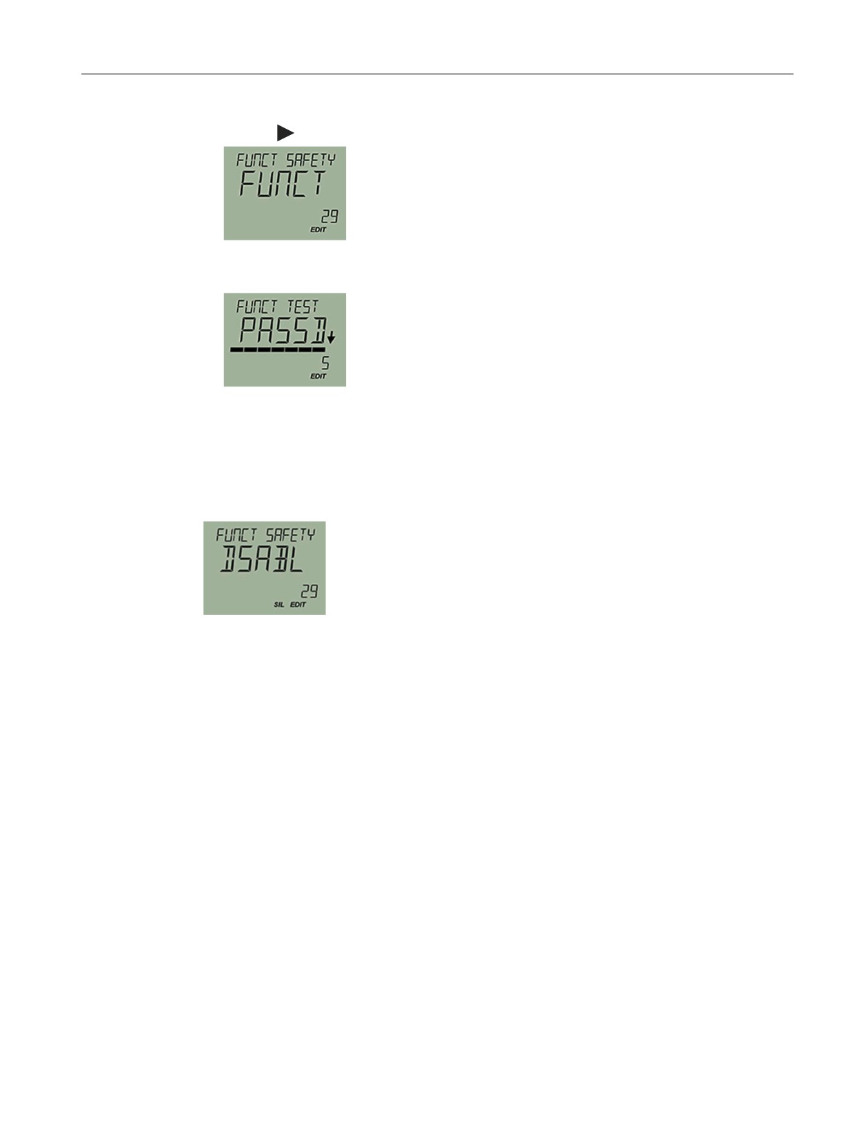
2. Select the parameter "Functional Safety" [29].
3. To start the wizard, enter the user PIN if needed.
4. Use the
button to confirm.
The display test runs automatically.
5. Check that the numbers, texts and symbols are displayed correctly.
6. Once the display test is complete, start the validation of the safety-related parameters and
the safety function.
When you select "ENABL", you enable Functional Safety directly without validation of the
safety-related parameters and the safety function.
SITRANS P320/P420 with 4 to 20 mA/HART
167

Functional Safety
10.2 Enabling Functional Safety
Validating safety-related parameters
1. Select "VALID".
2. Use the
button to confirm.
3. Navigate to the safety-related parameters with the
button.
To correct the safety-related parameters, exit the wizard with the
button. Use the
button to confirm.
Note
Write protection via user PIN is automatically enabled 10 minutes after the last button
operation. The wizard therefore aborts and the validation of the safety-related parameters
is lost.
● To start the wizard again, enter the user PIN.
4. To complete validation of the safety-related parameters, confirm with YES.
5. To validate the safety function, start the function test with "START".
When you select "SKIP", you skip the function test and enable Functional Safety directly
without validation of the safety function.
Validate safety function
1. Check the correct execution of the safety function in which the device is used.
2. In the parameter view, select the "Functional Safety" parameter [29].
3. To continue with the wizard, enter the user PIN if needed.
4. Select "START".
SITRANS P320/P420 with 4 to 20 mA/HART
168
Functional Safety
10.2 Enabling Functional Safety
5. Use the
button to confirm.
6. When you have successfully validated the safety function, restart the wizard and select
"PASSD".
The message "SAFETY MODE ON" (Functional Safety enabled) appears.
Result
The device is in the "Functional Safety enabled" device mode.
Figure 10-3
Parameter view
● The "SIL" symbol is displayed.
● The "DSABL" command appears (Disable Functional Safety).
● All parameters are protected against changes.
● When a safety-related error is detected on the device, the device changes to "Safety critical
error" device mode (Page 174).
See also
Troubleshooting (Page 197)
Diagnostic messages (Page 192)
SITRANS P320/P420 with 4 to 20 mA/HART
169

Functional Safety
10.2 Enabling Functional Safety
10.2.2
Enabling Functional Safety over remote operation
Requirement
● You have documented the device identification:
- During installation, you have read and documented the product name and the serial
number on the nameplate of the device.
- You have defined and documented a long tag (Page 146).
● You have checked the settings of the safety-related parameters.
Safety-related parameters (Page 165)
● You have selected one of the following characteristic curves using the "Application"
parameter [05]:
- Linear, proportional to pressure
- Linear, proportional to level
- Volume flow: two step linear, square root.
- Mass flow: two step linear, square root.
● You have enabled the "User PIN" parameter [27].
The user PIN you use is not the preset user PIN (2457).
Procedure
1. Select the menu command "Functional Safety".
2. Enter the user PIN.
SITRANS P320/P420 with 4 to 20 mA/HART
170
Functional Safety
10.2 Enabling Functional Safety
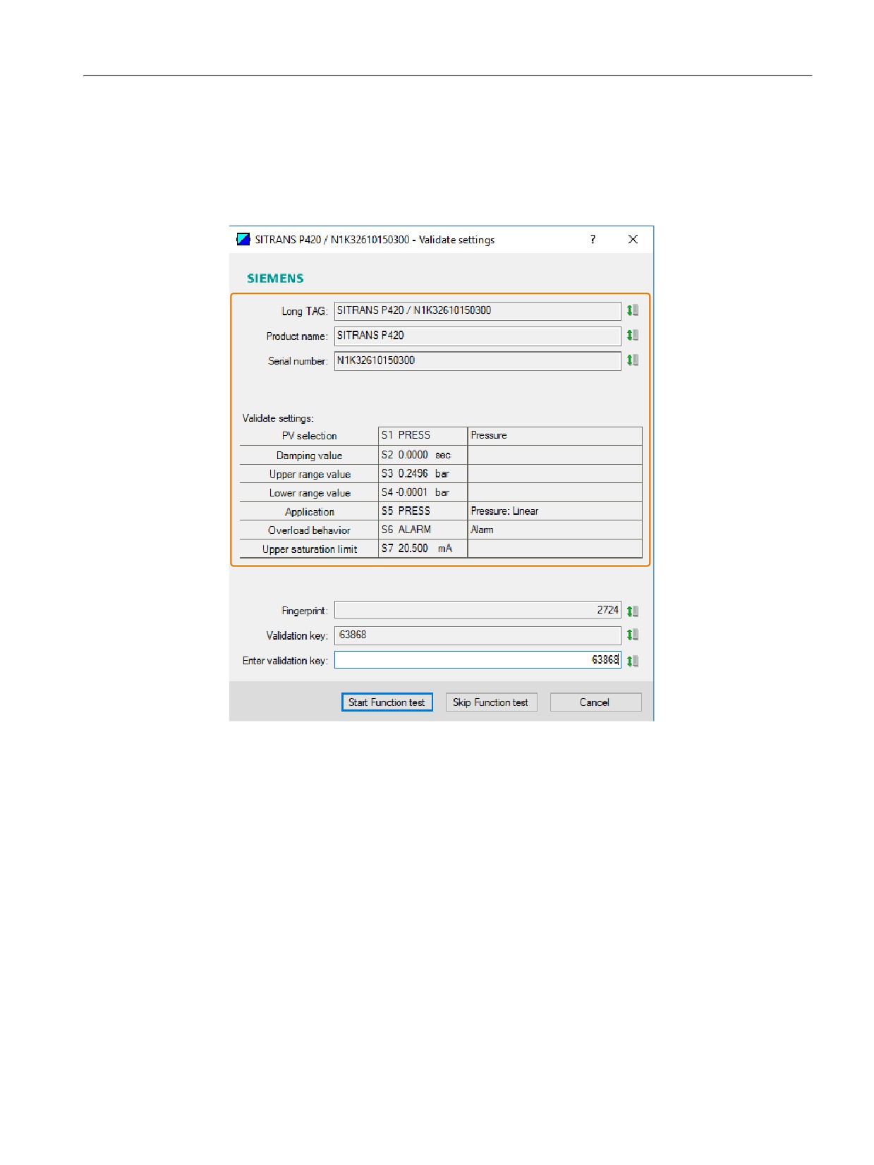
3. Validate the following settings:
- Identification data of your device: Long tag, product name, serial number.
- Settings of the safety-related parameters
To change the settings, exit the wizard with "Cancel".
4. Write down the fingerprint.
Whenever you start the validation, the device generates a fingerprint. By comparing the
fingerprint, you determine whether or not the device and the safety-related parameters have
changed erroneously during activation of the functional safety.
SITRANS P320/P420 with 4 to 20 mA/HART
171

Functional Safety
10.2 Enabling Functional Safety
5. To confirm the validation, enter the validation key.
6. To validate the safety function, start the function test.
The device changes to the "Safety validation" device mode.
7. Confirm with "OK".
Validate safety function
1. Check the correct execution of the safety function in which the device is used.
2. Select the "Functional Safety" wizard.
SITRANS P320/P420 with 4 to 20 mA/HART
172

Functional Safety
10.2 Enabling Functional Safety
3. Enter the user PIN.
4. Validate the identification data of your device.
5. Check that the displayed fingerprint matches the fingerprint you have written down.
6. Confirm the successful function test.
Result
The device is in the "Functional Safety enabled" device mode.
● All parameters are protected against changes.
● When a safety-related error is detected on the device, the device changes to "Safety critical
error" device mode (Page 174).
Note
The system shows unexpected data or behaves differently than described in this procedure.
● Repeat the entire procedure.
See also
Diagnostic messages (Page 192)
SITRANS P320/P420 with 4 to 20 mA/HART
173
Functional Safety
10.3 Acknowledging safety-related errors
10.3
Acknowledging safety-related errors
10.3.1
"Safety critical error" device mode
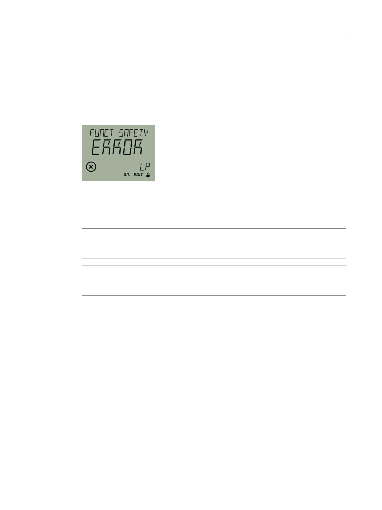
When a safety-related error is detected on the device, the current output signal corresponds to
the fault current and the diagnostic message is displayed.
Figure 10-4
Example: Diagnostic message for overview
Acknowledge the safety-related error with the "Functional Safety" parameter [29] via local
operation or via the menu command "Functional Safety" through remote operation. (Page 175)
The device then restarts and returns to the "Functional Safety disabled" device mode.
Note
The system shows unexpected data or behaves differently than described in this procedure.
● Repeat the entire procedure.
Note
Damaged device
● Replace the device.
See also
Select fault current [10] (Page 124)
SITRANS P320/P420 with 4 to 20 mA/HART
174

Functional Safety
10.3 Acknowledging safety-related errors
10.3.2
Acknowledging safety-related errors via remote operation
Procedure
1. Select the menu command "Functional Safety".
2. Enter the user PIN.
3. Validate the identification data of your device: Long tag, product name and serial number.
SITRANS P320/P420 with 4 to 20 mA/HART
175
Functional Safety
10.4 Disabling Functional Safety over device with display
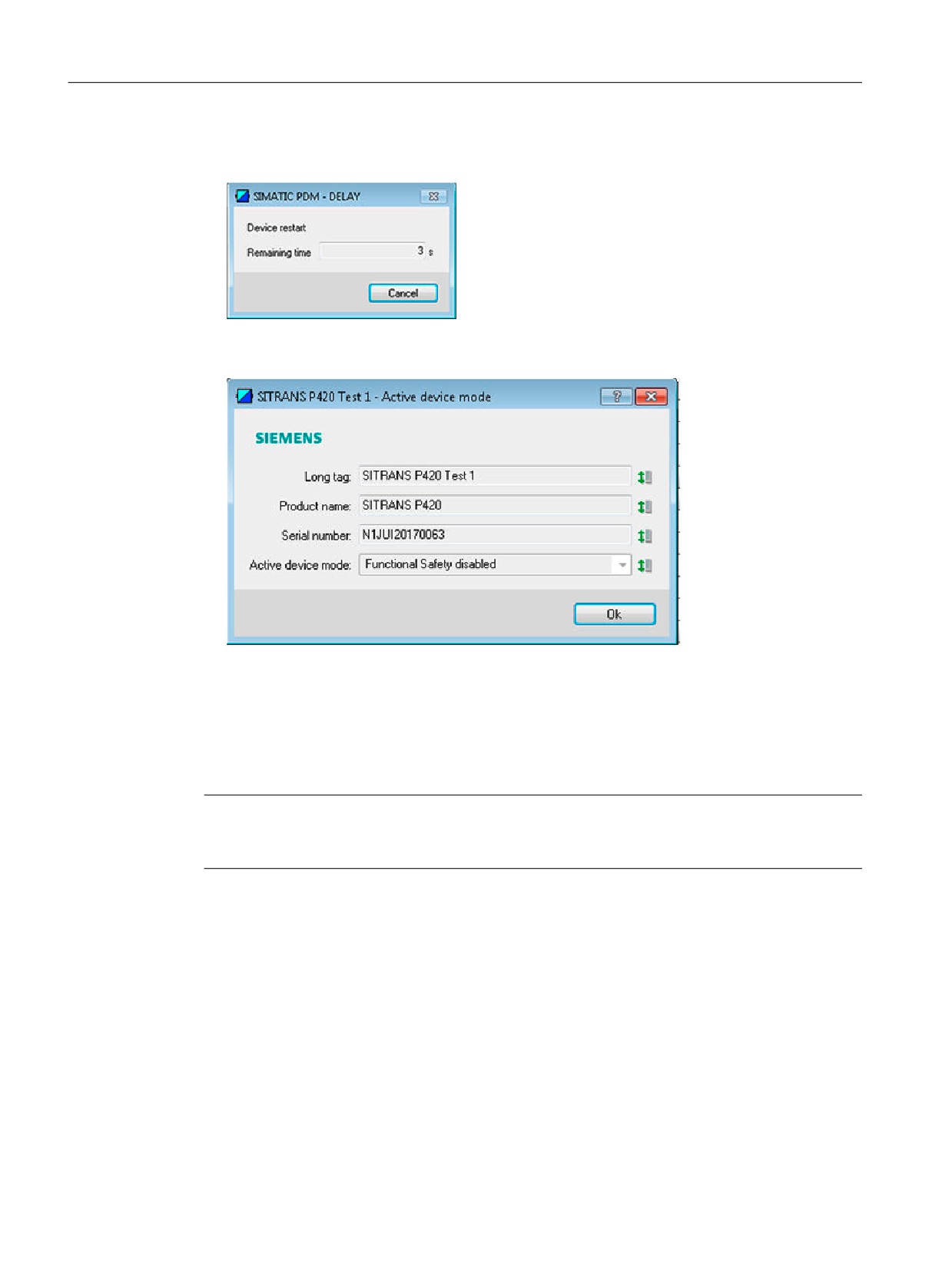
4. To acknowledge the safety-related error, click on "Acknowledge".
The device restarts automatically.
5. Validate the identification data of your device again: Long tag, product name and serial
number.
Result
● The safety-related error is acknowledged.
● The device returns to the "Functional Safety disabled" device mode.
Note
The system shows unexpected data or behaves differently than described in this procedure.
● Repeat the entire procedure.
10.4
Disabling Functional Safety over device with display
Requirement
The device is in the "Functional Safety enabled" device mode.
SITRANS P320/P420 with 4 to 20 mA/HART
176

Functional Safety
10.5 Disabling Functional Safety over remote operation
Procedure
1. Navigate to the parameter view.
Navigating in the views (Page 76)
2. Select the parameter "Functional Safety" [29].
3. Enter the user PIN.
The wizard starts.
4. Select YES immediately and confirm wit the
button.
Result
The device switches to "Functional Safety disabled" device mode.
● The "SIL" symbol is displayed.
● The "ENABL" command appears (Enable Functional Safety mode).
Note
If Functional Safety remains enabled, repeat the procedure described above without any
interruptions.
10.5
Disabling Functional Safety over remote operation
Requirement
The device is in the "Functional Safety enabled" device mode.
Procedure
1. Select the menu command "Functional Safety".
2. Enter the user PIN.
3. Validate the identification data of your device: Long tag, product name and serial number.
4. Confirm with "Ok" that you want to disable Functional Safety.
5. Validate the identification data of your device again: Long tag, product name and serial
number.
6. Confirm with "OK".
SITRANS P320/P420 with 4 to 20 mA/HART
177

Functional Safety
10.6 Proof test
Result
The device is in the "Functional Safety disabled" device mode.
Note
The system shows unexpected data or behaves differently than described in this procedure.
● Repeat the entire procedure.
10.6
Proof test
Proof tests can detect errors in the device that are not detected by the integrated diagnostics
of the device.
Proof tests performed at regular intervals uncover undetected errors that can otherwise cause
safety-related functions to function not as intended.
The interval between two proof tests is dependent on the safety-related system, based on the
combined calculations of failure rates for the system.
10.6.1
Intervals and rules for proof test
To ensure reliable operation of the safety function, perform the following proof tests at the
following intervals:
All devices
Read the information on maintenance intervals and checking the seals and cable glands in the
section Maintenance and repair work (Page 182).
Absolute pressure devices
Set the zero point every 5 years for the following variants:
Measuring cell
Absolute pressure from the rela-
Absolute pressure from the dif-
tive pressure/Absolute pressure
ferential pressure series
with front-flush diaphragm
250 mbar a/25 kPa a/100 H2O
7MF0.2. - .F ... -
7MF0.3. - .G ... -
1300 mbar a/130 kPa a/525 H2O
7MF0.2. - .L ... -
7MF0.3. - .L ... -
5000 mbar a/500 kPa a/72.5 psi a
7MF0.2. - .P ... -
7MF0.3. - .P ... -
30 bar a/3 MPa a/435 psi a
7MF0.2. - .R ... -
7MF0.3. - .R ... -
SITRANS P320/P420 with 4 to 20 mA/HART
178
Functional Safety
10.7 Repair and service
You can find information on how to set the zero point for absolute pressure in section Adjusting
zero point (absolute pressure) (Page 121)
Note
To set the zero point, first disable Functional Safety.
10.6.2
Documenting a proof test
Documentation of the results of the proof test must be part of the safety management system
of the installation. Errors that are of critical importance for Functional Safety must be reported
to Siemens Technical Support.
10.7
Repair and service
NOTICE
Repair and service
Repair and service work may only be performed by personnel authorized by Siemens.
SITRANS P320/P420 with 4 to 20 mA/HART
179
Functional Safety
10.7 Repair and service
SITRANS P320/P420 with 4 to 20 mA/HART
180

Service and maintenance
11
11.1
Basic safety instructions
The device is maintenance-free. However, a periodic inspection according to pertinent
directives and regulations must be carried out.
An inspection can include, for example, check of:
● Ambient conditions
● Seal integrity of the process connections, cable entries, and cover
● Reliability of power supply, lightning protection, and grounds
WARNING
Dust layers above 5 mm
Risk of explosion in hazardous areas. Device may overheat due to dust build up.
● Remove dust layers in excess of 5 mm.
WARNING
Use of a computer in a hazardous area
If the interface to the computer is used in the hazardous area, there is a risk of explosion.
● Ensure that the atmosphere is explosion-free (hot work permit).
CAUTION
Releasing button lock
Improper modification of parameters could influence process safety.
● Make sure that only authorized personnel may cancel the button locking of devices for
safety-related applications.
NOTICE
Penetration of moisture into the device
Device damage.
● Make sure when carrying out cleaning and maintenance work that no moisture penetrates
the inside of the device.
SITRANS P320/P420 with 4 to 20 mA/HART
181

Service and maintenance
11.3 Maintenance and repair work
11.2
Cleaning
11.2.1
Cleaning the enclosure
Cleaning the enclosure
● Clean the outside of the enclosure with the inscriptions and the display window using a cloth
moistened with water or a mild detergent.
● Do not use any aggressive cleansing agents or solvents, e.g. acetone. Plastic parts or the
painted surface could be damaged. The inscriptions could become unreadable.
NOTICE
Improper cleaning of diaphragm
Device damage. The diaphragm can be damaged.
● Do not use sharp or hard objects to clean the diaphragm.
11.2.2
Servicing the remote seal measuring system
The remote seal measuring system usually does not need servicing.
If the mediums are contaminated, viscous or crystallized, it could be necessary to clean the
diaphragm from time to time. Use only a suitable solvent to remove the deposits from the
diaphragm. Do not use corrosive cleaning agents. Prevent the diaphragm from getting
damaged due to sharp-edged tools.
11.3
Maintenance and repair work
WARNING
Impermissible repair of explosion protected devices
Risk of explosion in hazardous areas
● Repair must be carried out by Siemens authorized personnel only.
SITRANS P320/P420 with 4 to 20 mA/HART
182

Service and maintenance
11.3 Maintenance and repair work
WARNING
No maintenance interval has been defined
Device failure, device damage, and risk of injury.
● Define a maintenance interval for recurring tests depending on the use of the device and
your own experience.
● The maintenance interval will vary from site to site depending on corrosion resistance.
WARNING
Maintenance during continued operation in a hazardous area
There is a risk of explosion when carrying out repairs and maintenance on the device in a
hazardous area.
● Isolate the device from power.
- or -
● Ensure that the atmosphere is explosion-free (hot work permit).
WARNING
Impermissible accessories and spare parts
Risk of explosion in areas subject to explosion hazard.
● Only use original accessories or original spare parts.
● Observe all relevant installation and safety instructions described in the instructions for the
device or enclosed with the accessory or spare part.
WARNING
Hot, toxic or corrosive process media
Risk of injury during maintenance work.
When working on the process connection, hot, toxic or corrosive process media could be
released.
● As long as the device is under pressure, do not loosen process connections and do not
remove any parts that are pressurized.
● Before opening or removing the device ensure that process media cannot be released.
SITRANS P320/P420 with 4 to 20 mA/HART
183

Service and maintenance
11.3 Maintenance and repair work
WARNING
Improper connection after maintenance
Risk of explosion in areas subject to explosion hazard.
● Connect the device correctly after maintenance.
● Close the device after maintenance work.
Refer to Technical data (Page 199).
CAUTION
Hot surfaces
Risk of burns during maintenance work on parts having surface temperatures exceeding
70 °C (158 °F).
● Take corresponding protective measures, for example by wearing protective gloves.
● After carrying out maintenance, remount touch protection measures.
11.3.1
Checking the seals
Inspect the seals at regular intervals
Note
Incorrect seal changes
Incorrect measured values will be displayed. Changing the seals in a process flange of a
differential pressure measuring cell can alter the lower range value.
● Changing seals in devices with differential pressure measuring cells may only be carried out
by personnel authorized by Siemens.
Note
Using the wrong seals
Using the wrong seals with flush-mounted process connections can cause measuring errors
and/or damage the diaphragm.
● Always use seals which comply with the process connection standards or are
recommended by Siemens.
1. Clean the enclosure and seals.
2. Check the enclosure and the seals for cracks and damage.
3. If necessary, lubricate the seals or replace them.
SITRANS P320/P420 with 4 to 20 mA/HART
184
Service and maintenance
11.3 Maintenance and repair work
11.3.2
Check cable glands
● Check the tightness of the cable glands at regular intervals.
● Tighten the cable glands if necessary.
11.3.3
Replacing spare parts
11.3.3.1
Replacing electrical connections and cable entries
Procedure
1. Read the operating data and the approval information on the nameplates of your device.
2. Order a suitable electrical connection or cable entry for your device (cable gland, sealing
plug or device plug).
To do this, use the article number "7MF7906-..".
Notes for cable glands and device plugs
● When you order a cable gland or a device plug as spare part, consider the following criteria:
- Thread
- Material
- Approval
- IP degree of protection
- Permissible ambient temperature
● The permissible ambient temperature for devices with dust explosion protection deviates
from the permissible ambient temperature of the cable gland and the device plug.
You should therefore not use any cable glands or device plugs from third-party
manufacturers for devices with dust explosion protection.
11.3.3.2
Replacing the display
Removing the display
1. De-energize the device.
2. Use a 3 mm Allen key to loosen the front safety catch.
3. Unscrew the front cover.
SITRANS P320/P420 with 4 to 20 mA/HART
185

Service and maintenance
11.3 Maintenance and repair work
4. Remove the display from the holder.
5. Disconnect the cable of the display from the 4-pole connector ①.
1
Installing the display
1. Connect the cable of the display with the 4-pole connector ① by observing the poling:
1
2. Fasten the display in the holder.
SITRANS P320/P420 with 4 to 20 mA/HART
186
Service and maintenance
11.3 Maintenance and repair work
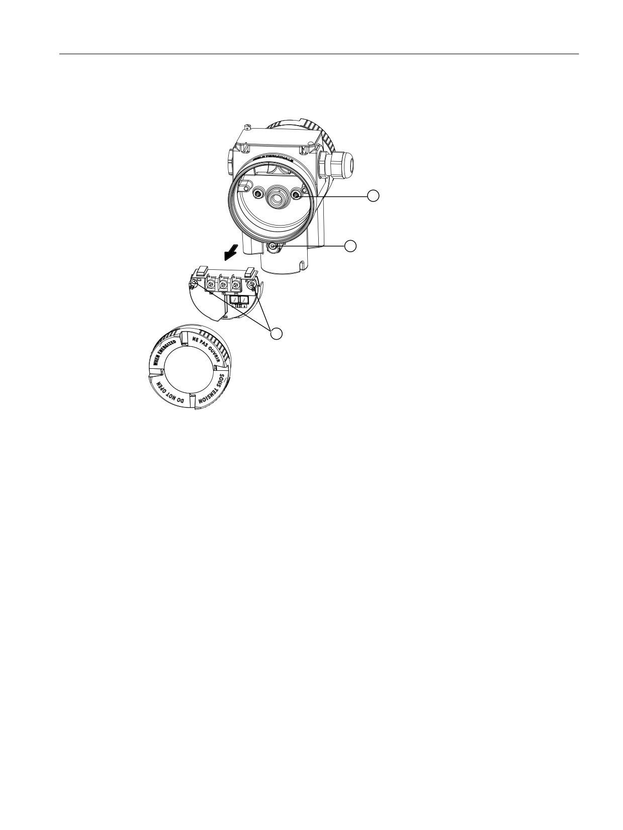
11.3.3.3
Replacing the termination board
Removing the termination board
1. De-energize the device.
2. Use a 3 mm Allen key to loosen the front safety catch ②.
3. Open the cover of the electronic connection compartment.
4. Disconnect the cables from the termination board.
5. On the left and right side, remove the recessed-head screws ① that hold the termination
board to the enclosure.
6. Remove the termination board.
Installing the termination board
1. Insert the new termination board so that its contact pins ③ fit on the rear of the termination
board.
2. Work in the reverse order to that described in "Removing the termination board".
SITRANS P320/P420 with 4 to 20 mA/HART
187
Service and maintenance
11.5 Disposal
11.4
Return procedure
Enclose the bill of lading, return document and decontamination certificate in a clear plastic
pouch and attach it firmly to the outside of the packaging.
Required forms
● Delivery note
with the following information:
- Product (item description)
- Number of returned devices/replacement parts
- Reason for returning the item(s)
With this declaration you warrant "that the device/replacement part has been carefully
cleaned and is free of residues. The device/replacement part does not pose a hazard for
humans and the environment."
If the returned device/replacement part has come into contact with poisonous, corrosive,
flammable or water-contaminating substances, you must thoroughly clean and
decontaminate the device/replacement part before returning it in order to ensure that all
hollow areas are free from hazardous substances. Check the item after it has been cleaned.
Any devices/replacement parts returned without a decontamination declaration will be
cleaned at your expense before further processing.
11.5
Disposal
Devices described in this manual should be recycled. They may not be
disposed of in the municipal waste disposal services according to the Di-
rective 2012/19/EC on waste electronic and electrical equipment (WEEE).
Devices can be returned to the supplier within the EC, or to a locally ap-
proved disposal service for eco-friendly recycling. Observe the specific
regulations valid in your country.
Further information about devices containing batteries can be found at:
Information on battery/product return (WEEE) (https://
support.industry.siemens.com/cs/document/109479891/)
Note
Special disposal required
The device includes components that require special disposal.
● Dispose of the device properly and environmentally through a local waste disposal
contractor.
SITRANS P320/P420 with 4 to 20 mA/HART
188

Diagnostics and troubleshooting
12
12.1
Device status symbols
Device status is shown using symbols on the local display. Additionally, the symbol and
respective text message for each device status can be seen in remote engineering, asset
management or process control systems.
Locally, in measurement view, alarms are shown as a symbol in the lower line of the display.
If several diagnostic states are active at the same time, the symbol for the most critical state is
shown.
Device status characteristics
The following table provides possible cause of device status and actions for the user or service.
The symbols used on the local display are based on NAMUR status signals, whereas symbols
used in SIMATIC PDM are based on Siemens standard alarm classes.
Note
Device status priority conflict - Namur vs Siemens standard
When more than one diagnostic event is active simultaneously, a conflict in priorities may arise.
In this case, the Namur symbol on the local display will differ from that shown in SIMATIC PDM.
● For example: if both diagnostic states "Maintenance demanded" and "Configuration error"
are active,
- Local display (using Namur symbols) will show "Configuration error" as higher priority.
- SIMATIC PDM (using Siemens standard symbols) will show "Maintenance demanded"
as higher priority.
Be aware of the priority for each device status, depending on the interface used.
Note
Namur device status priorities
This device uses Namur device status priorities based on HCF specification.
The sequence of symbols in the table corresponds to the priority of the device status, beginning
with the most critical.
SITRANS P320/P420 with 4 to 20 mA/HART
189

Diagnostics and troubleshooting
12.1 Device status symbols
Device status symbols
Display
NAMUR
SIMATIC PDM/PLC
– NAMUR NE 107
- HCF
Symbol
Device status
Priority *
Symbol
Device status
Priority *
Failure
1
Maintenance alarm
1
Cause: Output signal invalid due to fault in the field device or in the peripherals.
Measure: Maintenance is required immediately.
Maintenance
4
Maintenance demanded
2
required
Cause:Output signal is still valid, but wear reserve is almost exhausted and/or a function will be limited soon.
Measure:Maintenance is strongly recommended as soon as possible.
Maintenance
4
Maintenance required
3
required
Cause: The output signal is still valid. No functional restrictions have been determined but the wear reservice will most likely
be exhausted in the next few weeks.
Measure: Maintenance of device should be planned.
Function test
2
Manual operation
4
Cause: Output signal temporarily invalid (e.g. frozen) due to work being performed on the device.
Measure: Manual mode over HMI or disable the engineering system.
Function test
2
Simulation mode
5
Cause: The output signal does temporarily not reflect the process because the output is based on a simulation value.
Measure: Simulation mode over HMI or disable the engineering system or restart device.
Failure
1
Out of service
6
Cause: The output signal does not represent the process value. The device mode is set to "Out of service".
Measure: Disable "Out of service" and enable normal operation.
Failure
1
Configuration error
7
(red)
Cause: Output signal invalid due to parameter setting, connection error or configuration error in the HW.
Measure: Check hardware configuration of the device over HMI or engineering system.
SITRANS P320/P420 with 4 to 20 mA/HART
190

Diagnostics and troubleshooting
12.1 Device status symbols
Display
NAMUR
SIMATIC PDM/PLC
– NAMUR NE 107
- HCF
Symbol
Device status
Priority *
Symbol
Device status
Priority *
Out of specifica-
3
Process value alarm
8
tion
Cause: Deviations from permissible ambient or process conditions detected by the device (by means of self-monitoring or
based on warnings/errors in the device) indicate that the measured value is unreliable or that deviations from the set value in
the actuators are most likely greater than anticipated under normal operating conditions.
Process or ambient conditions can damage the device or result in unreliable results.
Measure: Check ambient temperature or process conditions. If possible, install device at different location.
Function test
2
Configuration warning
9
(yellow)
Cause: Safety validation is not complete.
Measure: Acknowledge safety event in the Functional Safety menu and repeat safety commissioning.
Out of specifica-
3
Process value warning
10
tion
Cause: Deviations from permissible ambient or process conditions detected by the device (by means of self-monitoring or
based on warnings/errors in the device) indicate that the measured value is unreliable or that deviations from the set value in
the actuators are most likely greater than anticipated under normal operating conditions.
Process or ambient conditions can damage the device or result in unreliable results.
Measure: Check ambient temperature or process conditions. If possible, install device at different location.
No symbol is
Process value tolerance
11
displayed
Cause: At least one process value violates one of the process tolerance limits set in the device parameters.
Measure: Check the parameter settings for limits for this application.
No symbol is
No symbol is
Configuration changed
12
displayed
displayed
Cause:The device configuration has changed due to a work process.
Measure: Reset configuration bit memory to delete the diagnostic message.
No symbol is
Good - OK
No symbol is
No assignment
13
displayed
displayed
Cause: Device state ok. No errors from active diagnostics.
Measure: No action required.
* The smallest number indicates the highest level of error severity.
** In SIMATIC PDM, the Siemens standard symbol as well as the corresponding NA\ symbol is
displayed (by the device display).
SITRANS P320/P420 with 4 to 20 mA/HART
191

Diagnostics and troubleshooting
12.2 Diagnostic messages
12.2
Diagnostic messages
The following table shows the IDs of diagnostic messages and possible causes and
instructions for corrective actions.
ID
Symbols
Message
Cause/Remedy
A0
Event counter 1
The number of overruns of the process value (set in parameters
"Upper limit" and "Monitored value") has reached the threshold.
Number overruns above
threshold
Reset and acknowledge event counter.
Maintenance alarm
Check process conditions.
Check limit monitoring and event counter settings.
A1
Event counter 1
The number of underruns of the process value (set in parameters
"Lower limit" and "Monitored value") has reached the threshold.
Number underruns above
threshold
Reset and acknowledge event counter.
Process value alarm
Check process conditions.
Check limit monitoring and event counter settings.
A2
Event counter 1
The number of underruns of the process value (set in parameters
"Lower limit" and "Monitored value") has reached the threshold.
Number underruns above
threshold
Reset and acknowledge event counter.
Maintenance required
Check process conditions.
Check limit monitoring and event counter settings.
A3
Event counter 1
The number of underruns of the process value (set in parameters
"Lower limit" and "Monitored value") has reached the threshold.
Number underruns above
threshold
Reset and acknowledge event counter.
Maintenance alarm
Check process conditions.
Check limit monitoring and event counter settings.
A4
Event counter 2
The number of overruns of the process value (set in parameters
"Upper limit" and "Monitored value") has reached the threshold.
Number overruns above
threshold
Reset and acknowledge event counter.
Process value alarm
Check process conditions.
Check limit monitoring and event counter settings.
A6
Event counter 2
The number of overruns of the process value (set in parameters
"Upper limit" and "Monitored value") has reached the threshold.
Number overruns above
threshold
Reset and acknowledge event counter.
Maintenance required
Check process conditions.
Check limit monitoring and event counter settings.
A7
Event counter 2
The number of overruns of the process value (set in parameters
"Upper limit" and "Monitored value") has reached the threshold.
Number overruns above
threshold
Reset and acknowledge event counter.
Maintenance alarm
Check process conditions.
Check limit monitoring and event counter settings.
A8
Event counter 2
The number of underruns of the process value (set in parameters
"Lower limit" and "Monitored value") has reached the threshold.
Number underruns above
threshold
Reset and acknowledge event counter.
Process value alarm
Check process conditions.
Check limit monitoring and event counter settings.
SITRANS P320/P420 with 4 to 20 mA/HART
192

Diagnostics and troubleshooting
12.2 Diagnostic messages
ID
Symbols
Message
Cause/Remedy
A9
Event counter 2
The number of underruns of the process value (set in parameters
"Lower limit" and "Monitored value") has reached the threshold.
Number underruns above
threshold
Reset and acknowledge event counter.
Maintenance required
Check process conditions.
Check limit monitoring and event counter settings.
AA
Device lifetime: Maintenance
Forthcoming end of configured device's lifetime.
demanded
Maintenance is strongly recommended as soon as possible.
Ab
Device lifetime: Maintenance
Forthcoming end of configured device's lifetime.
required
Maintenance of device should be planned.
AC
Sensor lifetime: Maintenance
Forthcoming end of configured sensor's lifetime.
demanded
Maintenance is strongly recommended as soon as possible.
Ad
Sensor lifetime: Maintenance
Forthcoming end of configured sensor's lifetime.
required
Maintenance of device should be planned.
AE
Service: Maintenance deman-
Forthcoming end of the configured service interval.
ded
Maintenance is strongly recommended as soon as possible.
AF
Service: Maintenance required
Forthcoming end of the configured service interval.
Maintenance of device should be planned.
AG
Calibration: Maintenance de-
Forthcoming end of the calibration interval.
manded
Maintenance is strongly recommended as soon as possible.
AH
Calibration: Maintenance re-
Forthcoming end of the calibration interval.
quired
Maintenance of device should be planned.
SITRANS P320/P420 with 4 to 20 mA/HART
193

Diagnostics and troubleshooting
12.2 Diagnostic messages
ID
Symbols
Message
Cause/Remedy
AJ
Limit monitoring 1
Monitored value is above limit (set in parameter "Upper limit").
Above limit
Process value alarm
AL
Limit monitoring 1
Monitored value is below limit (set in parameter "Lower limit").
Below limit
Process value alarm
An
Limit monitoring 2
Monitored value is above limit (set in parameter "Upper limit").
Above limit
Process value alarm
Ao
Limit monitoring 2
Monitored value is below limit (set in parameter "Lower limit").
Below limit
Process value alarm
AU
Event counter 1
The number of overruns of the process value (set in parameters
"Upper limit" and "Monitored value") has reached the threshold.
Number overruns above
threshold
Reset and acknowledge event counter.
Process value alarm
Check process conditions.
Check limit monitoring and event counter settings.
AY
Event counter 1
The number of overruns of the process value (set in parameters
"Upper limit" and "Monitored value") has reached the threshold.
Number overruns above
threshold
Reset and acknowledge event counter.
Maintenance required
Check process conditions.
Check limit monitoring and event counter settings.
bE
Out of service
The output signal does not represent the process value. The device
mode is set to "Out of service".
Maintenance alarm
Repair required. Contact Technical Support.
bL
Device restart due to unexpec-
Watchdog function has detected an internal device error.
ted program error
Restart the device.
Maintenance alarm
If the problem persists, contact Technical Support.
bn
Alarm sensor limit exceeded
Process value has reached the sensor limit.
Process value alarm
Review process conditions versus product specifications.
SITRANS P320/P420 with 4 to 20 mA/HART
194

Diagnostics and troubleshooting
12.2 Diagnostic messages
ID
Symbols
Message
Cause/Remedy
bS
Event counter 2
The number of underruns of the process value (set in parameters
"Lower limit" and "Monitored value") has reached the threshold.
Number underruns above
threshold
Reset and acknowledge event counter.
Maintenance alarm
Check process conditions.
Check limit monitoring and event counter settings.
CA
Simulation mode
The device is in simulation mode and one or more of its device vari-
ables are not representative of the process.
Disable the simulation to return to normal operation.
Cb
Diagnostics simulated
The device is in simulation mode.
Simulation mode
Disable the simulation to return to normal operation.
Co
Loop current fixed
The loop current is being held at a fixed value and is not responding
to process variations.
Manual operation
Enter the loop current output value for simulation.
Disable the simulation to return to normal operation.
CP
Loop current in saturation
The loop current has reached its upper (or lower) saturation limit and
cannot increase (or decrease) any further.
Process value warning
Adjust loop current scaling.
CU
PV status: uncertain
The value is outside of the physical sensor range. Accuracy may
decrease.
Process value alarm
Check for changes in process conditions or obstructions in vessel.
CY
PV status: bad
The measured value is 10% higher than the physical sensor range.
Maintenance alarm
Review process conditions versus product specifications.
Use a device that fulfills your process conditions.
Fb
Supply voltage below limit.
The supply voltage is too low.
Maintenance demanded
Make sure input voltage is within product specification.
FC
Supply voltage above limit
The supply voltage is too high.
Maintenance alarm
Make sure input voltage is within product specification.
SITRANS P320/P420 with 4 to 20 mA/HART
195

Diagnostics and troubleshooting
12.2 Diagnostic messages
ID
Symbols
Message
Cause/Remedy
FE
Loop current read back error
The loop current does not correspond to the expected value.
Maintenance demanded
Check DAC trim settings.
Restore to factory DAC calibration.
If the problem persists, contact Technical Support.
FJ
Process conditions outside the
Uncertain values due to process conditions.
specification
Check installation for abnormal operating conditions.
Process value warning
Fn
Connection error to sensor
Potential product damage.
electronics.
Restart the device.
Maintenance alarm
If error continues, sensor electronics may have a defect.
Repair required. Contact Technical Support.
Fo
Sensor break
Potential product damage.
Maintenance alarm
Sensor has malfunctioned.
A replacement of sensor is recommended.
Contact Technical Support.
Fr
Internal power supply is out of
A replacement of the device is recommended.
allowable range.
Contact Technical Support.
Process value warning
FS
Electronics defect
Defect of device electronics.
Maintenance alarm
A replacement of the device is recommended.
Contact Technical Support.
SA
Non-volatile memory check fail-
Device electronics error.
ure
Restart the device.
Maintenance alarm
If error continues, device electronics may have a defect.
Repair is required. Contact Technical Support.
Sb
Volatile memory check failure
Device electronics error.
Maintenance alarm
Restart the device.
If error continues, device electronics may have a defect.
Repair is required. Contact Technical Support.
SC
Invalid device configuration
One or more of parameters are set to invalid values.
Configuration error
Review configuration values and adjust as necessary.
(red)
SITRANS P320/P420 with 4 to 20 mA/HART
196

Diagnostics and troubleshooting
12.3 Troubleshooting
ID
Symbols
Message
Cause/Remedy
St
Safety validation mode
Device is in safety validation mode.
Configuration warning
Complete the functional test and confirm that it was successful in the
Functional Safety wizard.
(yellow)
SU
Safety critical device error
Acknowledge the error in menu "Functional Safety". If the device
does not display an error, repeat the safety start up.
Maintenance alarm
Acknowledging safety-related errors (Page 174)
If the problem persists, contact Technical Support.
12.3
Troubleshooting
Symptom
Cause of error
Remedy
Display empty,
No or incorrect supply voltage
Check the voltage at the terminals, the connections and
no transmission
the wiring.
pulses
Display shows
Value too large to appear on the display
Adjust the unit so that a lower value can be displayed,
"#####" instead
e.g. by selecting bars instead of millibars.
of the current
Pressure units [01] (Page 106)
measured value
Below you can find explanations on how to correct problems when enabling Functional Safety.
Information mes-
Cause of error
Remedy
sage on the dis-
play
INVALID CFG
Write protection via user PIN disabled.
Activate write protection via the user PIN.
ACCES
Enable user PIN (Page 139)
INVALID CFG
Wrong characteristic curves selected.
Select one of the following characteristic curves:
TRNFK
● Linear, proportional to pressure (PRESS).
● Linear, proportional to level (LEVEL).
● Proportional to flow rate, two-step linear up to the
application point (VSLN2 or MSLN2).
INVALID CFG
Loop current fixed. Loop test or multidrop
To return to normal operation, disable the loop test or
mode are enabled.
multidrop mode.
LOOPT
Loop test [31] (Page 141)
INVALID CFG
Device in simulation mode: Pressure meas-
Disable simulation to return to normal operation.
ured value is simulated.
SIMUL
Simulate constant pressure values (Page 147)
INVALID CFG
Device in simulation mode: Diagnostics are si-
Disable simulation to return to normal operation.
mulated.
STSIM
Simulate diagnostics (Page 148)
INVALID CFG
Factory settings for Functional Safety are faul-
Replace the device.
ty.
PARAM
SITRANS P320/P420 with 4 to 20 mA/HART
197
Diagnostics and troubleshooting
12.3 Troubleshooting
SITRANS P320/P420 with 4 to 20 mA/HART
198

Technical data
13
13.1
Input
13.1.1
Gauge pressure
Gauge pressure input
Measured variable
Gauge pressure
Measuring span (continuous-
Measuring span1)
Maximum permissible
Maximum test
ly adjustable) or measuring
operating pressure MAWP
pressure
range, max. operating pres-
(PS)
sure (in accordance with
8.3 … 250 mbar
4 bar
6 bar
2014/68/EU Pressure Equip-
0.83 ... 25 kPa
0.4 MPa
0.6 MPa
ment Directive) and max. test
pressure (in accordance with
0.12 … 3.6 psi
58 psi
87 psi
DIN 16086) (for oxygen
0.01 … 1 bar
6 bar
9 bar
measurement, max. 100 bar
1 ... 100 kPa
0.6 MPa
0.9 MPa
and 60 °C ambient tempera-
ture/process temperature)
0.15 … 14.5 psi
87 psi
130 psi
0.04 … 4 bar
20 bar
30 bar
4 ... 400 kPa
2 MPa
3 MPa
0.58 … 58 psi
290 psi
435 psi
0.16 … 16 bar
45 bar
70 bar
0.016 ... 1.6 MPa
4.5 MPa
7 MPa
2.3 … 232 psi
652 psi
1015 psi
0.63 … 63 bar
80 bar
120 bar
0.063 ... 6.3 MPa
8 MPa
12 MPa
9.1 … 914 psi
1160 psi
1740 psi
1.6 … 160 bar
240 bar
360 bar
0.16 ... 16 MPa
24 MPa
36 MPa
23 … 2321 psi
3480 psi
5221 psi
4 … 400 bar
400 bar
600 bar
0.4 ... 40 MPa
40 MPa
60 MPa
58 … 5802 psi
5802 psi
8702 psi
7 … 700 bar
800 bar
800 bar
0.7 ... 70 MPa
80 MPa
80 MPa
102 ... 10153 psi
11603 psi
11603 psi
Gauge pressure measuring limits
Low measuring limit2)
● Measuring cell with silicone oil filling
30 mbar a/3 kPa a/0.44 psi a
SITRANS P320/P420 with 4 to 20 mA/HART
199