Siemens SITRANS P. Operating Instructions (2019) - page 4

Parameter assignment
9.2 Parameter assignment over device with display
The following options are available to correct zero-point errors:
Device without display
Device with display
Remote operation
Press the
button and hold for
"Zero point adjustment" parame-
Device > Zero point adjustment
3 seconds.
ter
For special applications (e.g. level measurement for a closed vessel), you have the option of
shifting the zero point to a desired pressure value using the "Zero point adjustment" parameter.
You proceed differently depending on the device version.
9.2.6.1
Adjusting zero point (gauge pressure)
Requirement
The pressure measurement is stable.
Procedure
1. Vent the pressure connection of the device.
2. Navigate to the parameter view.
Navigating in the views (Page 76)
3. Select the "Zero point adjustment" parameter [07].
4. Press the
button.
The value "0" appears on the display and the "EDIT" symbol flashes.
5. Set the zero point to 0 or to the desired value.
6. Confirm the value by pressing the
button.
7. Change to the measurement view with the button.
Note
Depending on the damping setting, a settling time elapses until the pressure measurement 0
appears in the measurement view.
● For this reason, vent the pressure connection of the device up to the end of the operation.
Result
● The device displays the pressure measurement 0 in the set unit.
● The effective measuring range is reduced by the amount of the upstream pressure.
Example: With an upstream pressure of 100 mbar, the effective measuring range of a 1-bar
pressure transmitter is reduced to a point between 0 and 0.9 bar.
SITRANS P320/P420 with 4 to 20 mA/HART
120

Parameter assignment
9.2 Parameter assignment over device with display
9.2.6.2
Adjusting the zero point (differential pressure)
Requirement
The pressure measurement is stable.
Procedure
1. Make sure there is identical pressure in the two process connections.
2. Navigate to the parameter view.
Navigating in the views (Page 76)
3. In the parameter view, select the "Zero point adjustment" parameter [07].
4. Press the
button.
5. Set the zero point to 0 or to the desired value.
6. Confirm the value by pressing the
button.
7. Change to the measurement view with the button.
Note
Depending on the damping setting, a settling time elapses until the pressure measurement 0
is displayed.
● Make sure there is identical pressure in the two process connections until the end of the
operation.
Result
● The device displays pressure measurement 0 in the set unit.
● The effective measuring range is reduced by the amount of the upstream pressure.
Example: At a pre-load pressure of 25 mbar, the upper measuring range limit of a 250 mbar
pressure transmitter is reduced to 225 mbar.
9.2.6.3
Adjusting zero point (absolute pressure)
Requirement
You have created a reference pressure that is within the measurement limits.
Procedure
1. Navigate to the parameter view.
Navigating in the views (Page 76)
2. Select the "Zero point adjustment" parameter [07].
SITRANS P320/P420 with 4 to 20 mA/HART
121

Parameter assignment
9.2 Parameter assignment over device with display
3. Press the
button.
The value "0" appears on the display and the "EDIT" symbol flashes.
4. Enter the known reference pressure using the
or
buttons.
5. Confirm the value by pressing the
button.
6. Change to the measurement view with the button.
Result
The device displays pressure measurement 0 in the set unit.
Depending on the set damping, the settling time is extended until the pressure measurement
0 is displayed.
Note
For devices for absolute pressure, the lower range value is at vacuum (0 bar a).
The zero point adjustment for devices for absolute pressure that do not measure absolute
pressure (0 bar a) leads to incorrect settings.
9.2.7
Apply lower range value [08]/Apply upper range value [09]
9.2.7.1
Apply lower range value parameter [08]
Sets the lower range value to the current reference pressure.
Setting range:
Within the measuring limits
Factory setting:
See nameplate (depending on measuring cell)
9.2.7.2
Apply upper range value parameter [09]
Sets the upper range value to the current reference pressure.
Setting range:
Within the measuring limits
Factory setting:
See nameplate (depending on measuring cell)
9.2.7.3
Apply lower range value/upper range value (with pressure present)
Introduction
The lower range value (4 mA) corresponds to 0% of the measuring range. The upper range
value (20 mA) corresponds to 100% of the measuring range.
SITRANS P320/P420 with 4 to 20 mA/HART
122

Parameter assignment
9.2 Parameter assignment over device with display
With pressure present, you have the following options for assigning the desired pressure
measurements to the lower range value and the upper range value:
Device without display
Device with display
Remote operation
Apply lower range value
Hold down the
"Apply lower range val-
"Device > Apply values"
button
for 3 seconds.
ue" parameter [08]
menu
Apply upper range value
Hold down the
"Apply upper range val-
"Device > Apply values"
button
for 3 seconds.
ue" parameter [09]
menu
The minimum permissible measuring span of the measuring cell must not be fallen below. You
can find the minimum permissible measuring span of your measuring cell in the section
Technical data (Page 199)
Example: Measuring cell 0 to 16 bar
1. The measuring range is from 0 to 16 bar.
S >EDU@
, >P$@
2. You set the lower range value from 0 bar to 1 bar.
In order for the measuring span to stay constant, the upper range value is automatically
shifted from 16 bar to 17 bar.
S >EDU@
, >P$@
3. You set the upper range value from 17 bar to 15 bar.
S >EDU@
, >P$@
The measuring span is 14 bar.
Requirement
● A pressure is applied, e.g. the device is already mounted.
● The pressure is within the measuring limits.
Procedure
1. Navigate into the parameter view.
Navigating in the views (Page 76)
2. Select the "Apply lower range value" parameter [08].
SITRANS P320/P420 with 4 to 20 mA/HART
123

Parameter assignment
9.2 Parameter assignment over device with display
3. Press the
button.
The existing pressure is displayed.
4. Use the
button to confirm.
The wizard starts.
The wizard ends with the "COMPL" message.
5. Navigate to the "Apply upper range value" parameter [09].
The existing pressure is displayed.
6. Press the
button.
The wizard starts.
The wizard ends with the "COMPL" message.
Note
The wizard ends with the "FAILD" message in the following cases:
● The pressure exceeds or falls below the measuring limits.
● The measuring span is below the minimum permissible span.
9.2.8
Select fault current [10]
Selects whether the lower or upper fault current is output when a fault occurs (e.g. hardware/
firmware error, sensor break).
Setting range:
UPPER
Upper fault current
LOWER
Lower fault current
Factory setting:
LOWER , or as specified in order
Devices with functional safety
When a safety-related error is detected in the device in "Functional Safety enabled" device
mode, the current output signal corresponds to the lower fault current ≤ 3.55 mA.
9.2.9
Lower fault current [11]
Adjusts the magnitude of the lower fault current ②.
Setting range:
Between 3.55 mA and lower saturation limit ③
Factory setting:
3.55 mA, or as specified in order
SITRANS P320/P420 with 4 to 20 mA/HART
124

Parameter assignment
9.2 Parameter assignment over device with display
3.55 mA
3.8 mA
4 mA
20 mA
20.5 mA
22.8 mA
① Normal operation
② Lower fault current (factory setting)
③ Lower saturation limit (factory setting)
④ Upper saturation limit (factory setting)
⑤ Upper fault current (factory setting)
9.2.10
Upper fault current [12]
Adjusts the magnitude of the upper fault current ⑤.
Setting range:
Between upper saturation limit ④ und 22.8 mA
Factory setting:
22.8 mA, or as specified in order
3.55 mA
3.8 mA
4 mA
20 mA
20.5 mA
22.8 mA
① Normal operation
② Lower fault current (factory setting)
③ Lower saturation limit (factory setting)
④ Upper saturation limit (factory setting)
⑤ Upper fault current (factory setting)
9.2.11
Lower saturation limit [13]
Sets the lower threshold for the lower saturation limit③.
The loop current cannot drop below the set threshold.
Setting range:
Between lower fault current② and 4 mA
Factory setting:
3.8 mA, or as specified in order
SITRANS P320/P420 with 4 to 20 mA/HART
125

Parameter assignment
9.2 Parameter assignment over device with display
3.55 mA
3.8 mA
4 mA
20 mA
20.5 mA
22.8 mA
① Normal operation
② Lower fault current (factory setting)
③ Lower saturation limit (factory setting)
④ Upper saturation limit (factory setting)
⑤ Upper fault current (factory setting)
9.2.12
Upper saturation limit [14]
Sets the threshold for the upper saturation limit④.
Setting range:
Between 20 mA and the upper fault current
Factory setting:
20.5 mA, or as specified in order
3.55 mA
3.8 mA
4 mA
20 mA
20.5 mA
22.8 mA
① Normal operation
② Lower fault current (factory setting)
③ Lower saturation limit (factory setting)
④ Upper saturation limit (factory setting)
⑤ Upper fault current (factory setting)
SITRANS P320/P420 with 4 to 20 mA/HART
126

Parameter assignment
9.2 Parameter assignment over device with display
WARNING
Undetected failure in devices with functional safety
Note the following:
● For the maximum current output signal to be output, set the measuring range within the
maximum permissible measuring span. You can find the maximum permissible measuring
span of your measuring cell in the section Technical data (Page 199).
● Note that a saturation limit > 21.5 mA increases the risk of undetected failures. (Page 162)
● When you configure your process control system, the analog input must distinguish
between the measured value at saturation (current is ≤ 21.5 mA) and high fault current
(current is ≥ 22.0 mA).
9.2.13
SV selection [15]
Sets a measured value as a secondary variable (SV).
Setting range:
TEMP
Sensor temperature
ETEMP
Electronics temperature
LEVEL
Level
VOL
Volume
VFLOW
Volume flow
USER
Custom
MFLOW
Mass flow
Factory setting:
As specified in order
9.2.14
Units [16]
Introduction
Depending on the application of the device that you have selected using the "Application"
parameter, you have the option of selecting a unit:
● Level
● Volume
● Volume flow
● Mass flow
The selected unit is displayed in the measurement view.
Use the remote operation to set the associated unit for the "Customized characteristic curve"
application.
SITRANS P320/P420 with 4 to 20 mA/HART
127

Parameter assignment
9.2 Parameter assignment over device with display
See also
Application [05] (Page 110)
9.2.14.1
Level units [16]
Selects the unit for the "Level" measurement.
This parameter is only visible when you have selected the "Level" characteristic curve using the
"Application" parameter.
Setting range:
m
cm
mm
in
ft
Factory setting:
m
9.2.14.2
Volume units [16]
Selects the unit for the "Volume" measurement.
This parameter is only visible when you have selected a volume characteristic curve using the
"Application" parameter.
Certain units are displayed differently on the display and over remote operation. (Page 107)
Setting range:
Display (header line)
Display (enumeration)
Remote operation
Gal
Ga
gal
Gal [UK]
IGa
gal (UK)
l
l
l
hl
hl
hl
m3
m3
m3
in3
in3
in3
Ft3
Ft3
ft3
bu
bu
bu
Yd3
Yd3
yd3
bbl
bbl
bbl
bbl [US]
Ubb
bbl (US)
Nl
Nl
Nl
Nm3
Nm3
Nm3
SCF
SCF
SCF
Factory setting:
m3
9.2.14.3
Volume flow units [16]
Selects the unit for the "Volume flow" measurement.
SITRANS P320/P420 with 4 to 20 mA/HART
128

Parameter assignment
9.2 Parameter assignment over device with display
This parameter is only visible when you have selected a volume flow characteristic curve using
the "Application" parameter.
Certain units are displayed differently on the display and over remote operation. (Page 107)
Setting range:
Display (header line)
Display (enumeration)
Remote operation
m3/sec
m3/S
m³/s
m3/min
m3/m
m³/min
m3/h
m3/h
m³/h
m3/d
m3/d
m³/d
l/Sec
l/S
l/s
l/min
l/m
l/min
l/h
l/h
l/h
Ml/d
Ml/d
Ml/d
FT3/Sec
Ft3/S
ft³/s
Ft3/min
Ft3/m
ft³/min
Ft3/h
Ft3/h
ft³/h
Ft3/d
Ft3/d
ft³/d
SCF/min
SCF/m
SCF/min
SCF/h
SCF/h
SCF/h
Nl/h
Nl/h
Nl/h
Nm3/h
Nm3/h
Nm³/h
Gal[UK]/Sec
IGa/S
gal (UK)/s
Gal[UK]/min
IGa/m
gal (UK)/min
Gal [UK]/h
IGal/h
gal (UK)/h
Gal[UK]/d
IGa/d
gal (UK)/d
Gal/Sec
Ga/S
gal/s
Gal/min
Ga/m
gal/min
Gal/h
Ga/h
gal/h
Gal/d
Ga/d
gal/d
Mgal/d
MGI/d
Mgal/d
bbl/d
bbl/d
bbl/d
bbl/h
bbl/h
bbl/h
bbl/min
bbl/m
bbl/min
bbl/Sec
bbl/S
bbl/s
Factory setting:
m³/s
9.2.14.4
Mass flow units [16]
Selects the unit for the mass flow measurement.
This parameter is only visible when you have selected a mass flow characteristic curve using
the "Application" parameter.
SITRANS P320/P420 with 4 to 20 mA/HART
129

Parameter assignment
9.2 Parameter assignment over device with display
Certain units are displayed differently on the display and over remote operation. (Page 107)
Setting range:
Display (header line)
Display (enumeration)
Remote operation
KG/Sec
KG/S
kg/s
Gr/Sec
G/S
g/s
Gr/min
G/m
g/min
Gr/h
G/h
g/h
KG/min
KG/m
kg/min
KG/h
KG/h
kg/h
KG/d
KG/d
kg/d
t/min
t/m
t/min
t/h
t/h
t/h
t/d
t/d
t/d
lb/Sec
lb/S
lb/s
lb/min
lb/m
lb/min
lb/h
lb/h
lb/h
lb/d
lb/d
lb/d
ton/min
sto/m
ton/min
ton/h
sto/h
ton/h
ton/d
sto/d
ton/d
ton(UK)/h
Lto/h
ton (UK)/h
ton(UK)/d
Lto/d
ton (UK)/d
Factory setting:
kg/s
9.2.15
Temperature units [17]
Selects the temperature unit for the "Sensor temperature" and "Electronics temperature"
measurements that are displayed in the measurement view.
Setting range:
K
°C
°F
°R
Factory setting:
°C
9.2.16
Lower scaling point [18]
Sets the lower range value for the scaling.
Depending on the application of the device, you set the lower scaling point as follows:
SITRANS P320/P420 with 4 to 20 mA/HART
130

Parameter assignment
9.2 Parameter assignment over device with display
Level
Setting range:
Freely selectable numeric value
Factory setting:
0 m
Volume
Setting range:
Freely selectable numeric value
Factory setting:
0 m3
Volume flow
Setting range:
Freely selectable numeric value
Factory setting:
0 m3/s
Setting range:
Freely selectable numeric value
Factory setting:
0
Mass flow
Setting range:
Freely selectable numeric value
Factory setting:
0 kg/s
Setting range:
Freely selectable numeric value
Factory setting:
0
Custom units
Setting range:
Freely selectable numeric value
Factory setting:
USER DEFINED (custom), or as specified in order
Note
Bidirectional volume and mass flow measurement
Select a lower scaling value that is symmetrical to the upper scaling value. Example:
● Upper scaling value: 1000 m3/s
● Lower scaling value: -1000 m3/s
9.2.16.1
Set lower scaling point
1. Navigate to the parameter view.
Navigating in the views (Page 76)
2. Select the "Lower scaling point" parameter [18].
3. Use the
button to confirm.
4. Set the lower scaling point.
SITRANS P320/P420 with 4 to 20 mA/HART
131

Parameter assignment
9.2 Parameter assignment over device with display
9.2.17
Upper scaling point [19]
Sets the upper range value for the scaling.
Depending on the application of the device, you set the upper scaling point as follows:
Level
Setting range:
Freely selectable numeric value
Factory setting:
100 m
Volume
Setting range:
Freely selectable numeric value
Factory setting:
1000 m3
Volume flow
Setting range:
Freely selectable numeric value
Factory setting:
1000 m3/s
Mass flow
Setting range:
Freely selectable numeric value
Factory setting:
1000 kg/s
Custom units
Setting range:
Freely selectable numeric value
Factory setting:
USER DEFINED (custom), or as specified in order
9.2.17.1
Set upper scaling point
1. Navigate to the parameter view.
Navigating in the views (Page 76)
2. Select the "Upper scaling point" parameter [19].
3. Use the
button to confirm.
4. Set the upper scaling point.
9.2.18
Low flow cut-off [20]
Sets the flow value for the low flow cut-off. The flow value is suppressed up to certain
percentage of the output value.
SITRANS P320/P420 with 4 to 20 mA/HART
132
Parameter assignment
9.2 Parameter assignment over device with display
The parameter is visible when you have selected the "Hold at 0, square root" (VSOFF or
MSOFF) characteristic curve using the "Application" parameter.
Setting range:
0% - 100%
Factory setting:
10%
See also
Volume and mass flow measurements (Page 115)
9.2.19
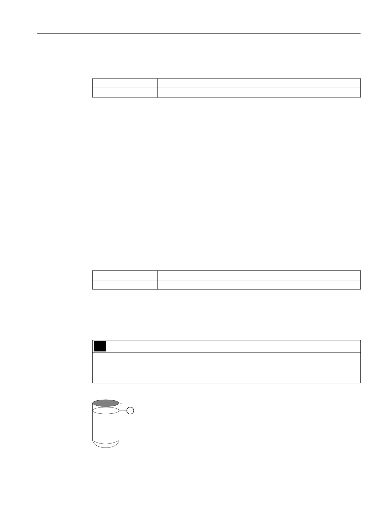
Vessel dimension A [21]
Sets the height of the vessel bottom for the following vessel shapes:
● Conical bottom vessel (CONIC)
● Parabolic bottom vessel (PARAB)
● Half sphere bottom vessel (HALF)
● Flat sloped bottom vessel (FLAT)
For a lying parabolic ends vessel (PARAE) the set value corresponds to the height of the end
piece.
You can find a figure with the different vessel shapes under "Volume measurement
(Page 118)".
Setting range:
0 to 100%
Factory setting:
0%
For the calculated volume to correspond to the actual vessel volume, set the parameters
Vessel dimension A and Vessel dimension L as follows:
● Vessel dimension L + 2 • Vessel dimension A = 100%.
Example: Vessel dimension L is 80% and vessel dimension A is 10%.
WARNING
Overfilling the vessel
To avoid overfilling the vessel, set a limit alarm: The limit must be below the maximum
measuring range ① and have a sufficient minimum distance to the top edge of the vessel.
SITRANS P320/P420 with 4 to 20 mA/HART
133

Parameter assignment
9.2 Parameter assignment over device with display
See also
Configuring limit monitoring (Page 154)
9.2.20
Vessel dimension L [22]
Sets the length of the bottom vessel for a lying parabolic ends vessel (PARAE).
You can find a figure with the different vessel shapes under "Volume measurement
(Page 118)".
Setting range:
0 to 100%
Factory setting:
0%
For the calculated volume to correspond to the actual vessel volume, set the parameters
Vessel dimension A and Vessel dimension L as follows:
● Vessel dimension L + 2 • Vessel dimension A = 100%.
Example: Vessel dimension L is 80% and vessel dimension A is 10%.
9.2.21
Button lock [23]
Enables the button lock. You can continue to operate the device using remote operation.
Setting range:
ON
Button lock enabled
OFF
Button lock disabled
Factory setting:
OFF
9.2.21.1
Enabling button lock
Procedure
1. Navigate into the parameter view.
Navigating in the views (Page 76)
2. In the parameter view, select the "Button lock" parameter.
3. Press the
button.
The "EDIT" symbol flashes.
SITRANS P320/P420 with 4 to 20 mA/HART
134

Parameter assignment
9.2 Parameter assignment over device with display
4. Select ON with the
or
button.
5. Use the
button to confirm.
Result
● The display automatically returns to the measurement view.
● The display automatically changes between the measured values every 12 seconds.
● The symbol for button lock "LL" and the measured value ID are displayed alternately.
Note
For a device without display, you activate the button lock using remote operation.
9.2.21.2
Disabling button lock
Procedure
To disable the button lock, press and hold the
button for 5 seconds.
Result
● The symbol for Button lock "LL" is hidden.
● You can operate the device using the buttons.
Note
For a device without display, you deactivate the button lock using remote operation.
9.2.22
Change user PIN [24]
Used to change the User PIN.
Setting range:
1 to 65535
Factory setting:
2457
SITRANS P320/P420 with 4 to 20 mA/HART
135

Parameter assignment
9.2 Parameter assignment over device with display
Requirement
The "User PIN (Page 139)" parameter is enabled.
Procedure
1. Navigate to the parameter view.
Navigating in the views (Page 76)
2. Select the parameter "Change user PIN".
3. Press the
button.
4. Enter the old user PIN.
5. Enter the new user PIN with a value between 1 and 65535.
Changing parameter values (Page 81)
6. Use the
button to confirm.
7. Repeat the new user PIN and use the button to confirm.
Result
● If both user PINs match, the "COMPL" message appears.
The user PIN has been successfully changed.
● If the two user PINs do not match, the "FAILD" message appears.
Then repeat the described procedure.
9.2.23
Recovery ID [25]
Shows the recovery ID.
SITRANS P320/P420 with 4 to 20 mA/HART
136

Parameter assignment
9.2 Parameter assignment over device with display
If you have forgotten your user PIN, you will need a recovery ID. The "Recovery ID" parameter
shows a number that is necessary for restoring the user PIN.
Figure 9-2
Example
9.2.23.1
Display Recovery ID
Requirements
The "User PIN" parameter is enabled.
Procedure
1. Navigate to the parameter view.
Navigating in the views (Page 76)
2. Select the "Recovery ID" parameter.
This Recovery ID is displayed.
Result
Please contact the Technical Support with the displayed recovery ID and the serial number of
your device.
You can find the serial number of the device on the nameplate or via remote operation.
Siemens Technical Support will give you a PUK (PIN Unlock Key) that you use to reset the user
PIN to the factory setting 2457.
9.2.24
PIN recovery [26]
Used to reset the user PIN to the factory setting.
The user PIN is factory set to 2457 in the device.
9.2.24.1
Recovering the user PIN
Requirement
● You have received the PUK from Technical Support. (Page 136)
● The "User PIN (Page 139)" parameter is enabled.
SITRANS P320/P420 with 4 to 20 mA/HART
137

Parameter assignment
9.2 Parameter assignment over device with display
Procedure
1. In the parameter view, select the "PIN recovery" parameter.
2. Press the
button.
The cursor and the "EDIT" symbol flash.
3. Enter the digits of the PUK:
- Use the or button to change.
- Use the button to confirm.
- Use the button to delete.
The complete PUK is shown on the top line of the display.
4. When the PUK is complete, use the button to confirm.
Result
● If you have entered the correct PUK, the message "NEW PIN - 2457" appears.
The user PIN has been reset to the factory setting 2457.
● If the PUK was not correctly entered, the message "FAILD" appears.
Then repeat the described procedure.
9.2.25
User PIN [27]
Used to enable or disable the user PIN.
Setting range:
ON
Enable user PIN
OFF
Disable user PIN
Factory setting:
User PIN disabled
When the user PIN is enabled, the measured values and parameters are read-only.
● To change the parameters and use the device functions, the user PIN must be input.
SITRANS P320/P420 with 4 to 20 mA/HART
138
Parameter assignment
9.2 Parameter assignment over device with display
The user PIN 2457 is factory preset in the device.
Note
Write protection is automatically enabled 10 minutes after the last button operation.
● Enter the user PIN.
9.2.25.1
Enable user PIN
Requirement
The User PIN is disabled.
Procedure
1. Navigate to the parameter view.
Navigating in the views (Page 76)
2. Select the parameter "User PIN".
3. Use the
button to confirm.
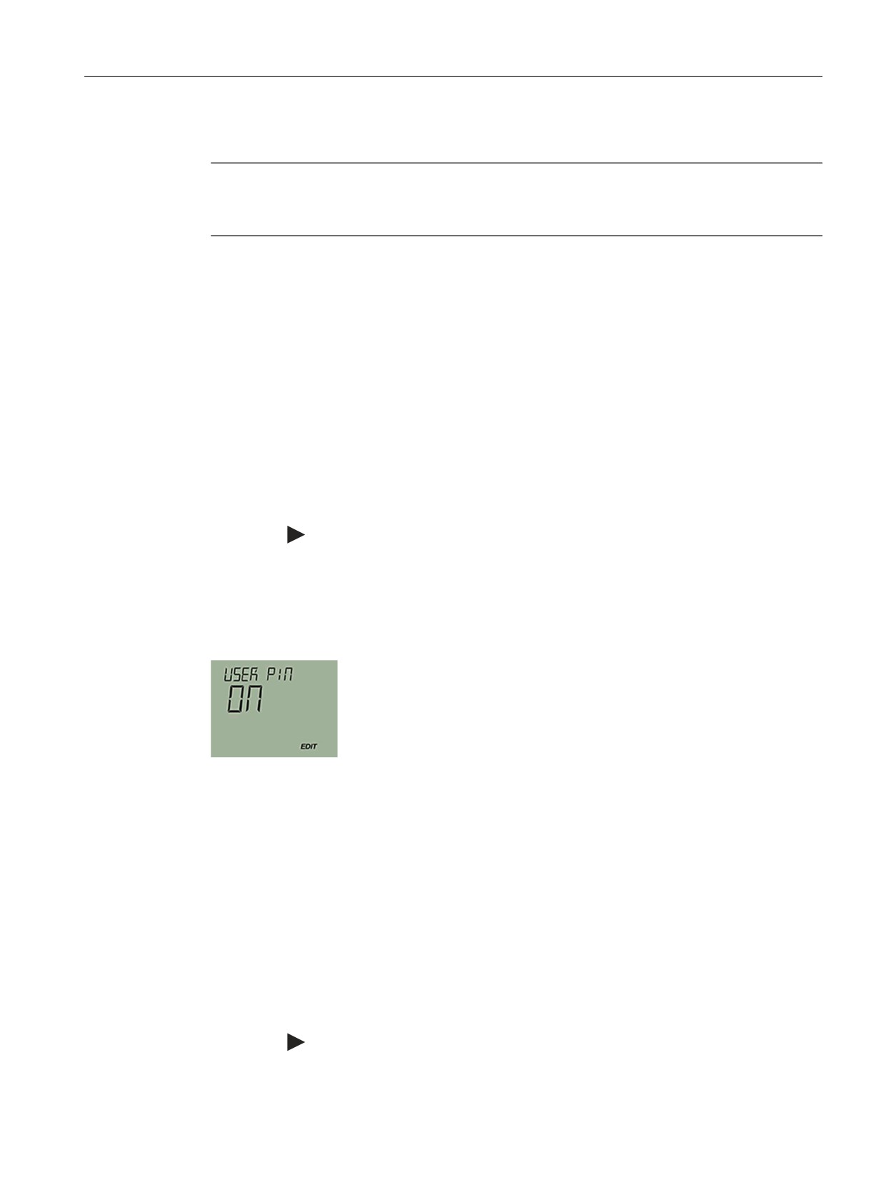
The message "USER PIN ON" (User PIN enabled) appears for 2 seconds.
Result
The User PIN is activated after about 10 minutes or after a device restart.
9.2.25.2
Disable user PIN
Requirement
The user PIN is enabled.
Procedure
1. Navigate to the parameter view.
Navigating in the views (Page 76)
2. Select the parameter "User PIN".
3. Use the
button to confirm.
SITRANS P320/P420 with 4 to 20 mA/HART
139

Parameter assignment
9.2 Parameter assignment over device with display
4. Select YES with the
or
button.
5. Use the
button to confirm.
The message "USER PIN OFF" appears for 2 seconds.
Result
The User PIN is disabled.
9.2.26
Active device mode [28]
Shows the mode in which the device is operated.
The parameter is only visible for devices with Functional Safety.
Setting range:
STD
Functional Safety is disabled
FUNCT
Validation of the safety-related parameters and/or the fail-
safe behavior is performed
SAFE
Functional Safety is enabled
ERROR
Safety critical device error
O/S
Out of service mode, non-safe mode
Factory setting:
STD
You can find additional information on the device modes under Device mode (Page 163).
9.2.27
Functional Safety [29]
Enables Functional Safety.
The parameter is only visible for devices with Functional Safety.
You can find additional information about functional safety under Functional Safety (Page 159).
SITRANS P320/P420 with 4 to 20 mA/HART
140

Parameter assignment
9.2 Parameter assignment over device with display
9.2.28
Display test [30]
Used to check that numbers, texts and symbols appear correctly on the display.
● To start the display test, press the
button and select "START".
When the display test is complete, the message "COMPL" appears.
● To cancel the display test, press the
button.
9.2.29
Loop test [31]
Sets a constant loop current for test purposes.
You have the option of selecting preset values or a user-defined value.
Setting range:
3.55 mA
4 mA
12 mA
20 mA
22.8 mA
USER
User defined
Factory setting:
12 mA
9.2.29.1
Loop test with preset loop current value
1. Navigate into the parameter view.
Navigating in the views (Page 76)
2. Select the parameter "Loop test".
3. Use the
button to confirm.
The loop test starts:
- The "EDIT" symbol flashes.
- The "Function check" symbol is displayed.
- The "Co" symbol (constant current mode) is displayed.
4. Change the preset value with the
or
button.
5. Use the
button to confirm.
The loop test starts.
6. End the loop test with the
button.
SITRANS P320/P420 with 4 to 20 mA/HART
141

Parameter assignment
9.2 Parameter assignment over device with display
9.2.29.2
Loop test with user defined loop current value
1. Navigate into the parameter view.
Navigating in the views (Page 76)
2. In the parameter view, select the "Loop test" parameter.
3. Use the
button to confirm.
The loop test starts:
- The "EDIT" symbol flashes.
- The "Function check" symbol is displayed.
- The "Co" symbol (constant current mode) is displayed.
4. Change to "USER" with the or button.
5. Use the
button to confirm.
6. Set a value between 3.6 mA and 22.8 mA using the buttons or
7. Use the
button to confirm.
The loop test starts.
8. End the loop test with the
button.
9.2.30
Start view [32]
Selects the value that is displayed as the first measured value in the measurement view.
For the selection to take effect, change from the parameter view to the measurement view or
restart the device.
Setting range:
Edit view
Measurement view
PRESS
Pressure (P1)
STEMP
Sensor temperature (P2)
ETEMP
Electronics temperature (P3)
LEVEL
Level (P4)
VOL
Volume (P5)
VFLOW
Volume flow (P6)
MFLOW
Mass flow (P7)
USER
Customized characteristic curve (P8)
%
Percent of range (P9)
LOOPC
Loop current (PA)
CVOLT
Terminal voltage (PB)
Factory setting:
PRESS
SITRANS P320/P420 with 4 to 20 mA/HART
142

Parameter assignment
9.2 Parameter assignment over device with display
Note
To have the process value for "Level", "Volume", "Mass flow", "Volume flow" or "Customized
characteristic curve" shown as the "Start view", first set the associated characteristic curve
using the "Application" (Page 110) parameter.
9.2.31
Pressure reference [33]
Used to adapt the display of the pressure unit to your application.
Setting range:
NONE
Not specified
GAUGE
Gauge pressure
ABS
Absolute pressure
Factory setting:
NONE
See also
Pressure units [01] (Page 106)
9.2.32
Identify the device [34]
Enables or disables the device identification via HART.
When device identification is enabled, the device signals its identification data via HART.
With device identification enabled, the device responds to a request with the HART command
"Find device".
Setting range:
ON
Device identification enabled
OFF
Device identification disabled
Factory setting:
OFF
9.2.33
Reset [35]
Used to reset the following settings:
Setting range:
Restore ordered configuration
CUST
Reset to sensor calibration
SENSR
Reset DAC trim to the factory setting
DAC
Factory reset
FACT
SITRANS P320/P420 with 4 to 20 mA/HART
143
Parameter assignment
9.2 Parameter assignment over device with display
9.2.33.1
Reset to sensor calibration
Resets the zero point and sensor calibration to the factory setting.
9.2.33.2
Reset DAC trim to the factory setting
Resets the DAC trim (digital-to-analog converter trim) to the factory setting.
The DAC trim is used to calibrate the 4 mA and 20 mA end points of the analog output with an
external reference (e.g. current measurement device).
The DAC trim is available over remote operation.
9.2.33.3
Restore ordered configuration
With this function you return your device to its delivery state.
●
The ordered configuration of the following parameters is restored:
- Pressure units
- Quick start
- Pressure reference
- Long tag (TAG)
- Short tag (TAG)
- Lower range value
- Upper range value
- Lower limit of the measuring range
- Upper limit of the measuring range
- Damping value
- Application and related values (e.g.: vessel shapes and application points)
- Fault current selection
- Lower fault current
- Upper fault current
- Lower saturation limit
- Upper saturation limit
- Custom units
●
The parameters that you have not configured via the order are reset to the factory settings.
9.2.33.4
Restore factory settings
With this function you return your device to its factory setting.
SITRANS P320/P420 with 4 to 20 mA/HART
144

Parameter assignment
9.3 Parameter assignment over remote operation
The following settings are reset to the factory setting among other things:
● Sensor calibration
● DAC trim
● The defaults that you have configured in your order.
These defaults can then deviate from the ordered configuration. To restore the ordered
configuration, use the "Restore ordered configuration (Page 144)" parameter.
9.2.34
Overload behavior [36]
Defines the reaction of the device when the measuring range of the sensor is exceeded (at
overpressure or underpressure).
If the parameter is set to "Warning", the current output follows the pressure value up to the
configured saturation limits. If the parameter is set to "Alarm", the lower fault current
(≤ 3.55 mA) is output when the sensor is overloaded.
The parameter is only visible for devices with functional safety and is only effective if the device
is in the "Functional Safety enabled" device mode.
Setting range:
WARN
Warning
ALARM
Alarm
Factory setting:
ALARM or as specified in order
The selected parameter setting influences the safety characteristics (Page 162).
9.3
Parameter assignment over remote operation
9.3.1
Introduction
This section describes the most important parameters and functions that are available
additionally over remote operation:
● "Quick Start" wizard
● Identification (TAG)
● Simulation
● Customized characteristic curve
● Sensor calibration
● Digital-to-analog converter trim (DAC trim)
● Diagnostics functions
- Limit monitoring and event counter (not available on SITRANS P320)
- Trend log (not available on SITRANS P320)
- Operating hours counter
SITRANS P320/P420 with 4 to 20 mA/HART
145

Parameter assignment
9.3 Parameter assignment over remote operation
9.3.2
Quick start
You use the "Quick start" wizard to configure your device in five steps for the required
application:
● Step 1: Identification
● Step 2: Application
● Step 3: Scaling
Note that you set the displayed pressure unit with the "Pressure units" (Page 107)
parameter and not with the wizard.
Set the unit of the selected application (e.g. volume, mass flow) also via the parameter
group "Settings > Current output > Scaling > Unit".
● Step 4: Fault current
● Step 5: Summary
The summary provides an overview of the "old" and "new" parameters.
To store the parameters in SIMATIC PDM and transfer them to the device, click the "Apply"
button.
9.3.3
Identification
Define the data that you need to identify your device under the "Identification" parameter group.
A distinction is made between data you can set yourself and values that are preset in the
factory.
The default values are write-protected and cannot be changed. The corresponding allocation
is set out in the following example:
Parameter
Adjustable
Preset
Factory setting
Tag
X
-
Long tag (TAG)
X
-
Description
X
-
Message
X
-
Installation date
X
-
Device
Manufacturer
-
X
Siemens
Product name
-
X
SITRANS P420
Article number
-
X
e.g. 7MF0440-1GL01-5AF2-Z
Order option 1/ Order option 2
-
X
e.g. A01+C11+C12+C14+C20+E00+H01+Y01+Y15+Y21
Serial number
-
X
In accordance with the measuring cell selection/device manufac-
ture
Final assembly number
X
-
Hardware version
-
X
In accordance with the measuring cell selection/device manufac-
ture
Firmware version
-
X
In accordance with the measuring cell selection/device manufac-
ture
EDD version
-
X
SITRANS P320/P420 with 4 to 20 mA/HART
146

Parameter assignment
9.3 Parameter assignment over remote operation
Parameter
Adjustable
Preset
Factory setting
Sensor serial number
-
X
In accordance with the measuring cell selection/device manufac-
ture
Sensor type
-
X
In accordance with the measuring cell selection/device manufac-
ture
Maximum measuring span
-
X
In accordance with the measuring cell selection/device manufac-
ture
9.3.4
Simulation
You can use the device to simulate the following via remote operation (e.g. field communicator,
SIMATIC PDM):
● Input and output values
- Constant pressure values
- Ramp function
● Diagnostics
9.3.4.1
Simulate constant pressure values
Procedure
To simulate a constant pressure value via remote operation (e.g. SIMATIC PDM), follow these
steps:
1. For the "Simulation mode" parameter, set the "Enabled" option to simulate a constant
pressure value.
2. Select the pressure value ("Process value") to be simulated from the drop-down list under
the "Simulation selection" parameter.
3. For the "Simulation value" parameter, set the desired constant pressure value for the
simulation.
4. Set status to be simulated for the "PV status" parameter.
5. Click "Transfer" to start the simulation.
6. For the "Simulation mode" parameter, set the "Disabled" option to stop the simulation.
Result
The measured value is replaced by a constant simulation value. The simulation influences the
output signal.
SITRANS P320/P420 with 4 to 20 mA/HART
147
Parameter assignment
9.3 Parameter assignment over remote operation
The diagnostic ID "Cb" is displayed on the device.
Note
The simulated pressure value has a direct effect on the configured process value (e.g. volume
or flow rate) and thus on the current output dependent on it.
9.3.4.2
Simulate ramp function
To simulate a ramp function via remote operation (e.g. SIMATIC PDM), follow these steps:
1. For the "Simulation mode" parameter, set the "Ramp" option to simulate a changing
pressure value.
2. Select the pressure value ("Process value") to be simulated from the drop-down list under
the "Simulation selection" parameter.
3. For the "Simulation value" parameter, set the desired start value for the simulation.
4. Set status to be simulated for the "PV status" parameter.
5. Set the "Ramp end" parameter .
6. Set the "Ramp steps" parameter to define the number of steps in the ramp simulation.
7. Set the "Ramp duration" parameter to define the time interval (in seconds) for each step in
the simulation.
8. Click "Transfer" to start the simulation.
9. For the "Simulation mode" parameter, set the "Disabled" option to stop the simulation.
Note
The simulated pressure value has a direct effect on the configured process value (e.g. volume
or flow rate) and thus on the current output dependent on it.
9.3.4.3
Simulate diagnostics
Procedure
To simulate diagnostics via remote operation (e.g. SIMATIC PDM), follow these steps:
1. Open the "Device" menu in SIMATIC PDM and select "Simulation > Diagnostics".
2. To put the device into simulation mode, press the "Enable" button in the "Simulation
diagnostics" tab.
(Button switches between "Enable" and "Disable").
3. Select the diagnostics you want to simulate from the drop-down box of the "Diagnostics"
field.
4. Select "Action" for each selected diagnostic action to be simulated: "On" or "Off".
5. To start the simulation, click on the "Apply and transfer" button.
SITRANS P320/P420 with 4 to 20 mA/HART
148

Parameter assignment
9.3 Parameter assignment over remote operation
The diagnostic status of the simulation selected for each diagnostic is displayed in additional
tabs in the dialog box. The simulated diagnostics is indicated by a check mark in the check box.
End diagnostics simulation
You close the simulation in the "Diagnostics simulation" tab:
● To disable a specific diagnostic action, click "Off" (under the "Action" field).
● To end the diagnostics simulation, click on the "Disable" button.
WARNING
When diagnostics simulation is enabled, diagnostic events of the real process are neither
recorded nor evaluated.
With activated diagnostics simulation, only the simulated diagnostics are displayed on the
device display.
Stop diagnostics simulation immediately after use:
● Click "Disable" in the "Diagnostics simulation" tab before you close the "Diagnostics"
dialog.
● Alternatively, you can restart the device.
9.3.5
Customized characteristic curve
9.3.5.1
Introduction
For special applications, a customized characteristic curve is available.
This application is used, for example, for volume measurement in vessels with unusual shapes.
You define the relationship between inlet pressure and outlet current according to your user-
specific requirements.
You have up to 32 breakpoints available for this, which you enter using the engineering system
and display graphically.
Example
For measurement with the customized characteristic curve, you set the following values, for
example:
Damping value:
2.0 s
Lower range value:
0 bar
Upper range value:
10 bar
Application:
Custom (CUSTM)
Unit:
Cans
Lower scaling point:
0 cans
SITRANS P320/P420 with 4 to 20 mA/HART
149
Parameter assignment
9.3 Parameter assignment over remote operation
Upper scaling point:
250 cans
x values:
0%, 25%, 50%, 75%, 100%
y values:
0%, 25%, 50%, 75%, 100%
9.3.5.2
"Custom units" parameter
Selects a custom unit.
The selected unit is displayed in the measurement view (Page 77).
Setting range:
Up to 12 characters
Factory setting:
0 or as specified in order
This parameter is only visible when you have selected a custom characteristic curve using the
"Application" parameter.
9.3.5.3
Set customized characteristic curve
Requirement
●
You have set the "Customized characteristic curve" application.
●
You have set a custom unit.
●
You have set the lower scaling point and the upper scaling point.
Procedure
1.
Select the "Customized characteristic curve" menu.
2.
Read the data from the device.
3.
Enter the desired number of breakpoints.
You can enter a minimum of two and up to 32 breakpoints.
4.
Enter the x values and y values.
Note
The x values must increase monotonically. Otherwise, the x values are not accepted by the
device.
The characteristic curve is displayed as diagram.
The x values are shown as pressure value or as percentage of the set pressure range.
The y values are displayed in the user-specific unit or as a percentage of the configured
user-specific range.
5.
Transfer the characteristic to the device.
Result
The output current now follows the set characteristic.
Values below the first breakpoint or above the last breakpoint are extrapolated.
SITRANS P320/P420 with 4 to 20 mA/HART
150

Parameter assignment
9.3 Parameter assignment over remote operation
See also
Application [05] (Page 110)
9.3.6
Sensor calibration
You use the sensor calibration to set the characteristic curve of the device at two trim points.
The results are then correct measured values at the sensor trim points.
The sensor trim points can be selected as any points within the nominal range.
Devices that are not turned down prior to delivery are trimmed at 0 bar and the high limit of the
nominal range.
Devices that are turned down prior to delivery are trimmed at the low and high limits of the set
measuring range.
Examples
● For a particular device that is not turned down (e.g. 63 bar), the typical measured value is
50 bar. To attain the highest possible accuracy for this value, set the upper sensor trim at
50 bar.
● A 63-bar pressure transmitter is turned down to 4 to 7 bar. You can attain the highest
possible accuracy by selecting 4 bar for the low trim point and 7 bar for the high trim point.
● A 250-mbar absolute pressure transmitter shows 25 mbar at 20 mbar. A reference pressure
of 20 mbar is available. To correct the zero point, perform a sensor trim at the lower trim point
with 20 mbar.
Note
Use a test device whose accuracy is at least three times as high as the accuracy of the
pressure transmitter.
Sensor calibration at the low calibration point
1. Use remote control (e.g. SIMATIC PDM) to select the menu command "Device > Sensor
calibration".
2. Apply the pressure for the low calibration point at the device.
3. Apply the pressure value that you have created and assign the pressure value to the device.
The device applies the set value.
The device carries out an offset correction of the characteristic curve.
SITRANS P320/P420 with 4 to 20 mA/HART
151

Parameter assignment
9.3 Parameter assignment over remote operation
Sensor calibration at the high calibration point
1. Use remote control (e.g. SIMATIC PDM) to select the menu command "Device > Sensor
calibration".
2. Apply the pressure for the high calibration point at the device.
The high calibration point needs to be greater than the low calibration point.
3. Apply the pressure value that you have created and assign the pressure value to the device.
The device applies the set value.
The device carries out an offset correction of the characteristic curve.
The low calibration point is not affected by this.
Result
$
%
3DUDOOHO VKLIW
0HDVXUHG
%
&
,QFOLQH FKDQJH
SUHVVXUH S
%
&
$
/RZ
+LJK
'HIDXOW
FDOLEUDWLRQ SRLQW
FDOLEUDWLRQ SRLQW
SUHVVXUH
A
Original characteristic
B
Characteristics after sensor calibration at the low calibration point
C Characteristics after sensor calibration at the high calibration point
9.3.7
Digital-to-analog converter trim (DAC trim)
Introduction
The current that is output by the device can be trimmed independently of the measuring circuit.
This function is designed for compensating inaccuracies in the processing chain following the
device.
SITRANS P320/P420 with 4 to 20 mA/HART
152

Parameter assignment
9.3 Parameter assignment over remote operation
Procedure
●
Trim at 4 mA:
Use the menu command "DAC trim" to instruct the device to put out 4 mA. You read the
measured value at an ammeter and enter this value. The device uses this value for offset
correction of the current.
●
Trim at 20 mA:
Use the menu command "DAC trim" to instruct the device to put out 20 mA. You read the
measured value at an ammeter and enter this value. The device uses this value for gradient
correction of the current. The value for 4 mA is not affected by this.
Note
If a multimeter is used, it must always be sufficiently accurate.
$
%
3DUDOOHO VKLIW
0HDVXUHG
%
&
9DULDWLRQ LQ ULVH
FXUUHQW ,
$
%
&
,
,
P$
P$
5DWHG FXUUHQW ,
A
Original characteristic
B
Characteristic curve after DAC trim 4 mA
C
Characteristic curve after DAC trim 20 mA
SITRANS P320/P420 with 4 to 20 mA/HART
153
Parameter assignment
9.3 Parameter assignment over remote operation
9.3.8
Diagnostics functions
9.3.8.1
Limit monitoring and event counter
Introduction
With the limit monitoring and event counter function, the following options are available to you
via remote operation (e.g. SIMATIC PDM):
● Monitoring process values
● Counting events based on configured limits
● Triggering, acknowledging and resetting process value alarms and warnings.
Configuring limit monitoring
Procedure
1. Select the menu command "Device > Limit monitoring and event counter".
The "Limit monitoring" tabs are displayed.
2. To trigger a process value alarm each time the value falls below or exceeds the limit, set the
"Limit monitoring" text box to "Enabled".
3. Select the process value (e.g. sensor temperature) that you want to monitor from the
"Monitored value" drop-down list.
Configure only one process value per tab.
4. In the "Upper limit", "Lower limit" and "Hysteresis" text boxes, enter the values that trigger
an event.
If the process value rises above the upper limit (overrun) or falls below the lower limit
(underrun), an event is counted based on the configured value for the hysteresis.
Hysteresis (Page 156)
5. If necessary, configure the event counter.
Configuring the event counter (Page 155)
6. Click on "Transfer".
Result
The process value alarm is displayed as a symbol for the status in the "Diagnostics > Device
state" dialog of the engineering system and on the device screen.
It is not necessary to acknowledge the process value alarms.
If the monitored process value is again within the limit values, the process value alarm is reset.
SITRANS P320/P420 with 4 to 20 mA/HART
154
Parameter assignment
9.3 Parameter assignment over remote operation
Configuring the event counter
Requirement
You have configured the following values in limit monitoring:
● Upper limit
● Lower limit
● Hysteresis
Configuring limit monitoring (Page 154)
Procedure
1. In the "Limit" text box, enter the number of underrun and overrun events that must be
reached in order to trigger the action for underrun and overrun respectively.
2. From the "Action" drop-down list, select whether process value alarms or warnings
(maintenance demanded and maintenance required) are triggered.
- If you set the action to "Disabled", no new process value alarms or warnings for the set
limit values are triggered, although the counter remains in operation.
All process value alarms and warnings that were triggered before the action was set to
Disabled remain pending until the event counter is reset.
3. Click on "Transfer".
Result
The configured diagnostics are triggered after the specified number of limit violations has been
reached (e.g. Maintenance required).
Process value alarms and warnings are displayed as symbols for the status in the "Diagnostics
> Device state" dialog in the engineering system and on the device screen.
These process value alarms and warnings must be acknowledged.
Acknowledging process value alarms and warnings (Page 155)
Acknowledging process value alarms and warnings
Requirement
You have configured the event counter.
Configuring the event counter (Page 155)
Procedure
1. Select the menu command "Device > Limit monitoring and event counter".
2. Click "Reset and acknowledge".
SITRANS P320/P420 with 4 to 20 mA/HART
155

Parameter assignment
9.3 Parameter assignment over remote operation
Result
Process value alarms and warnings are acknowledged and deleted.
The event counter is reset.
Hysteresis
The hysteresis works as follows:
/LPLWV ZLWK K\ᚔHUHVLV
$
%
0RQLWRUHG YDOXH
8SSHU OLPLW
+\ᚔHUHVLV
+\ᚔHUHVLV
/RZHU OLPLW
7LPH
/LPLWV ZLWKRXW K\ᚔHUHVLV
&
'
0RQLWRUHG YDOXH
8SSHU OLPLW
/RZHU OLPLW
7LPH
Limits with hysteresis
If you enter a non-zero value in the "Hysteresis" text box, the hysteresis is disabled.
Upper limit with hysteresis (A)
An overrun event is counted when the process value rises above the upper limit ①.
The next overrun event is counted when the process value falls below the lower limit minus the
entered hysteresis② and then rises above the upper limit③.
Two events are counted in the displayed time period within 'A'.
SITRANS P320/P420 with 4 to 20 mA/HART
156
Parameter assignment
9.3 Parameter assignment over remote operation
Lower limit with hysteresis (B)
An underrun event is counted when the process value falls below the lower limit ①.
The next underrun event is counted when the process value first rises above the lower limit plus
the entered hysteresis②, and then falls below the lower limit③.
Within 'B', two events are counted in the displayed period.
Limits without hysteresis
If you enter the value "zero" in the "Hysteresis" text box, the hysteresis is disabled.
Upper limit without hysteresis (C)
An overrun event is counted when the process value rises above the upper limit①.
The next overrun event is counted when the process value falls below the upper limit② by any
value, and then rises above the upper limit②.
Within 'C', three events are counted in the displayed period.
Lower limit without hysteresis (D)
An underrun event is counted when the process value falls below the lower limit① by any
value.
If the process value falls below the lower limit by any value ②, the next underrun event is
counted again.
Two events are counted in the displayed period within 'D'.
See also
Configuring limit monitoring (Page 154)
9.3.8.2
Trend log
Set trend log
1. Select the menu command "Device > Trend log settings".
2. Define the number of process values you wish to log.
3. Use the "Logging behavior" parameter to define the buffer behavior.
- To fill the buffer with a variable number of logging points between 1 to 735 per process
value, select "Fill and stop".
The buffer is deleted and filled up to the number of set logging points. Then logging is
stopped.
- If you select the buffer behavior "Overwrite", the buffer is completely deleted. After the
buffer size of 735 logging points per process value has been reached, the 15 oldest
logging points are cyclically replaced with 15 new logging points.
4. In the "Logging interval" parameter, enter the interval in seconds between the logging points.
SITRANS P320/P420 with 4 to 20 mA/HART
157
Parameter assignment
9.3 Parameter assignment over remote operation
5. Select the process values you want to record.
6. Click on "Transfer" to write the log settings to the device.
The buffer with the existing logging points is deleted and overwritten with new logging points.
Show trend log
1. Select the menu command "Diagnostics > Trend log".
2. Click on "Read".
- The number of available process values is displayed.
- The current number of logging points per process value that are already in the buffer is
displayed.
- The time stamp for the start time is displayed.
3. To show the first or second process value in the chart, enable the associated check box.
4. Click on "Read".
- The logging points in the buffer are read from the device and shown in the chart.
- The process values for pressure and sensor temperature are shown in different colors in
the chart.
When you click on "Reset", the buffer is deleted and trend logging starts again.
9.3.8.3
Operating hours counter
Operating hours counter for transmitter electronics
● Monitors the number of operating hours during which the transmitter remained in continuous
operation.
● Starts with the first commissioning at the factory.
● The operating hours counter cannot be reset or adjusted.
Operating hours counter for sensor electronics
● Is only displayed when the measuring transducer electronics was replaced.
● Monitors the number of operating hours during which the sensor electronics remained in
continuous operation.
Procedure
1. Use remote operation (e.g. SIMATIC PDM) to select the menu command "Diagnostics >
Device state".
2. Select the "HART status" tab.
The operating time and, if available, the sensor operating time is displayed.
SITRANS P320/P420 with 4 to 20 mA/HART
158
Functional Safety
10
Introduction
This section includes the required additional information for parameter assignment,
commissioning and maintenance of the device in a safety-instrumented system.
10.1
Safety concept
The device was developed in accordance with the Safety Integrity Level (SIL), which is defined
as a relative level of risk reduction offered by a safety function.
The individual device has a hardware fault tolerance of 0 (HFT = 0) and a systematic suitability
of 3. The device is classified as Type B device.
● The device meets the requirements of SIL 2 in single-channel safety-related systems.
● The device meets the requirements of SIL 3 in two-channel safety-related systems, when a
comparison function for checking the output of the two redundant devices comprising a
redundant system is implemented.
10.1.1
Random and systematic errors
Random errors can occur at any time. An example is an electronic circuit that is faulty
immediately.
Systematic errors occur under specific conditions and are reproducible, if the same conditions
arise again. An example is a software error that occurs under certain conditions.
There are random and systematic errors in hardware, but only systematic errors in software.
Note
Limitations in redundant systems
Redundancy significantly reduces the probability of a failure of the safety function due to a
random error but not the probability of systematic errors.
10.1.2
SIL-compliant product version
Information on specific versions that are permitted for use in safety-related systems according
to IEC 61508 can be found in the manufacturer's declaration of conformity for the device (SIL
declaration of conformity, Functional Safety according to IEC 61508).
SITRANS P320/P420 with 4 to 20 mA/HART
159