Siemens SITRANS P. Operating Instructions (2019) - page 2

Description
4.6 Remote seal and differential pressure flow measuring systems
4.6
Remote seal and differential pressure flow measuring systems
4.6.1
Remote seal
●
A remote seal measuring system comprises the following elements:
- Remote seal
- Transmission line, e.g. capillary line
- Pressure transmitter
Note
Malfunction of the remote seal measuring system
If you separate the components of the remote seal measuring system, this results in
malfunctioning of the system.
Do not separate the components under any circumstances.
●
The measuring system based on a hydraulic principle is used to transfer pressure.
●
The capillary line and the remote seal diaphragm are the most sensitive components in the
remote seal measuring system. The material thickness of the remote seal diaphragm is only
∼ 0.1 mm.
●
The smallest of leakages in the transmission system leads to the loss of transmission fluid.
●
The loss of transmission fluid results in inaccuracies in the measurement and failure of the
measuring system.
●
In order to avoid leaks and measuring errors, please observe the installation and
maintenance instructions in addition to the safety notes.
See also
Installation with remote seal (Page 54)
4.6.2
Differential pressure - flow measuring systems
A differential pressure flow measuring system consists of the following components:
● Primary element, e.g. orifice or averaging pitot tube
● Shutoff fitting, valve manifold
● Pressure transmitter
Application examples for differential pressure and flow with primary elements, refer to section
Differential pressure and flow rate (Page 94).
You can find additional information on primary elements in the associated instructions under:
SITRANS P320/P420 with 4 to 20 mA/HART
40
Description
4.6 Remote seal and differential pressure flow measuring systems
4.6.3
Remote seals and primary element for devices with functional safety
Remote seals and primary elements were not included in the evaluation of the devices with
respect to functional safety.
If you use a remote seal or a primary element, make sure that you include the associated safety
characteristic values when evaluating your device with respect to functional safety.
For more information on evaluating the functional safety of your application, contact Technical
Support.
SITRANS P320/P420 with 4 to 20 mA/HART
41
Description
4.6 Remote seal and differential pressure flow measuring systems
SITRANS P320/P420 with 4 to 20 mA/HART
42

Installing/mounting
5
5.1
Basic safety instructions
DANGER
Pressure applications
Danger to personnel, system and environment will result from improper disassembly.
● Never attempt to loosen, remove, or disassemble process connection while vessel
contents are under pressure.
WARNING
Wetted parts unsuitable for the process media
Risk of injury or damage to device.
Hot, toxic and corrosive media could be released if the wetted parts are unsuitable for the
process medium.
● Ensure that the material of the device parts wetted by the process medium is suitable for
the medium. Refer to the information in Technical data (Page 199).
WARNING
Unsuitable connecting parts
Risk of injury or poisoning.
In case of improper mounting, hot, toxic, and corrosive process media could be released at the
connections.
● Ensure that connecting parts (such as flange gaskets and bolts) are suitable for connection
and process media.
WARNING
Exceeded maximum permissible operating pressure
Risk of injury or poisoning.
The maximum permissible operating pressure depends on the device version, pressure limit
and temperature rating. The device can be damaged if the operating pressure is exceeded.
Hot, toxic and corrosive process media could be released.
Ensure that maximum permissible operating pressure of the device is not exceeded. Refer to
the information on the nameplate and/or in Technical data (Page 199).
SITRANS P320/P420 with 4 to 20 mA/HART
43

Installing/mounting
5.1 Basic safety instructions
WARNING
Incorrect material for the diaphragm in Zone 0
Risk of explosion in the hazardous area. If operated with intrinsically safe supply devices of
category "ib" or devices of the flameproof enclosure version "Ex d" and simultaneous use in
Zone 0, pressure transmitter explosion protection depends on the tightness of the diaphragm.
● Ensure that the material used for the diaphragm is suitable for the process medium. Refer
to the information in the section "Technical data (Page 199)".
WARNING
Loss of safety for devices with "flameproof enclosure" type of protection
Risk of explosion in hazardous areas. An explosion may be caused by hot gas escaping from
the flameproof enclosure if there is too little space between it and fixed parts (e.g. walls, pipes).
● Ensure that there is a minimum clearance of at least 40 mm between the flameproof joints
and the fixed parts.
① Flameproof joint
WARNING
Using safety extra-low voltage for devices of the protection type "db", "ec", "tb" or "tc"
Risk of explosion in hazardous areas.
● Isolate the non-intrinsically safe circuit safely from ground, e.g.: through a SELV circuit.
SITRANS P320/P420 with 4 to 20 mA/HART
44

Installing/mounting
5.1 Basic safety instructions
WARNING
Vibrations in the plant
Risk of injury or damage to device.
Vibration leads to material fatigue, for example, cracks and weld seams breaks.
Hot, toxic and corrosive process media can emerge.
● Make sure that you have mounted the pressure transmitter (including accessories)
protected against vibration.
Refer to the information on vibration resistance in the section Technical specifications.
CAUTION
Hot surfaces resulting from hot process media
Risk of burns resulting from surface temperatures above 65 °C (149 °F).
● Take appropriate protective measures, for example contact protection.
● Make sure that protective measures do not cause the maximum permissible ambient
temperature to be exceeded. Refer to the information in Technical data (Page 199).
CAUTION
External stresses and loads
Damage to device by severe external stresses and loads (e.g. thermal expansion or pipe
tension). Process media can be released.
● Prevent severe external stresses and loads from acting on the device.
Note
Material compatibility
Siemens can provide you with support concerning selection of sensor components wetted by
process media. However, you are responsible for the selection of components. Siemens
accepts no liability for faults or failures resulting from incompatible materials.
SITRANS P320/P420 with 4 to 20 mA/HART
45

Installing/mounting
5.1 Basic safety instructions
5.1.1
Installation location requirements
WARNING
Insufficient air supply
The device may overheat if there is an insufficient supply of air.
● Install the device so that there is sufficient air supply in the room.
● Observe the maximum permissible ambient temperature. Refer to the information in the
section Technical data (Page 199).
NOTICE
Aggressive atmospheres
Damage to device through penetration of aggressive vapors.
● Ensure that the device is suitable for the application.
NOTICE
Direct sunlight
Increased measuring errors.
● Protect the device from direct sunlight.
Make sure that the maximum ambient temperature is not exceeded. Refer to the information
in the section Technical data (Page 199).
5.1.1.1
Use in maritime deployment
Note
For vibrations in the direction of the measuring cell diaphragm, the measuring accuracy of the
pressure transmitter with flush-mounted diaphragm can deviate no more than 0.2% from the
respective specification.
● Install the device so that no or almost no vibrations occur in the direction of the diaphragms.
● To avoid measuring values that fluctuate strongly, use the damping function.
For information on vibration resistance, refer to the marine approval certificate.
SITRANS P320/P420 with 4 to 20 mA/HART
46

Installing/mounting
5.2 Installing
5.1.2
Proper mounting
WARNING
Incorrect mounting at Zone 0
Risk of explosion in hazardous areas.
● Ensure sufficient tightness at the process connection.
● Observe the standard IEC/EN 60079-14.
NOTICE
Incorrect mounting
The device can be damaged, destroyed, or its functionality impaired through improper
mounting.
● Before installing ensure there is no visible damage to the device.
● Make sure that process connectors are clean, and suitable gaskets and glands are used.
● Mount the device using suitable tools. Refer to the information in Technical data
(Page 199).
NOTICE
Use of line and cable entries made of plastic in hazardous areas
Device damage caused by impact at temperatures below -20 °C.
● Make sure that the line and cable entries are protected from impacts.
5.2
Installing
5.2.1
Introduction
The pressure transmitter can be configured above or below the pressure sampling point. The
recommended configuration depends on the aggregate state of the process medium.
Installation configuration for gases
Install the pressure transmitter above the pressure sampling point.
Lay the pressure tubing with a constant gradient to the pressure sampling point, so that any
condensation produced can drain in the main line and thereby avoid corruption of the measured
values.
Installation configuration for vapor and liquid
Install the pressure transmitter below the pressure sampling point.
SITRANS P320/P420 with 4 to 20 mA/HART
47
Installing/mounting
5.2 Installing
Lay the pressure tubing with a constant gradient to the pressure sampling point so that any gas
pockets can escape in the main line.
Mounting location
Verify that the mounting location meets the following conditions:
● Accessible
● Close to the measuring point
● Vibration-free
● Within the permitted ambient temperature values
Protect the pressure transmitter from:
● Direct heat radiation
● Rapid temperature fluctuations
● Heavy contamination
● Mechanical damage
● Direct sunlight
Requirement
● You have compared the desired operating data with the data on the nameplate.
● You have adhered to the information on the remote seal during its installation.
Procedure
1. Attach the pressure transmitter to the process connection.
Use an appropriate tool (e.g. open-ended wrench with width across flats 36). Otherwise, the
measuring cell may be damaged.
2. Turn only on the key area above the process connection.
Caution: If you turn the pressure transmitter on the housing, the measuring cell may be
damaged.
SITRANS P320/P420 with 4 to 20 mA/HART
48
Installing/mounting
5.2 Installing
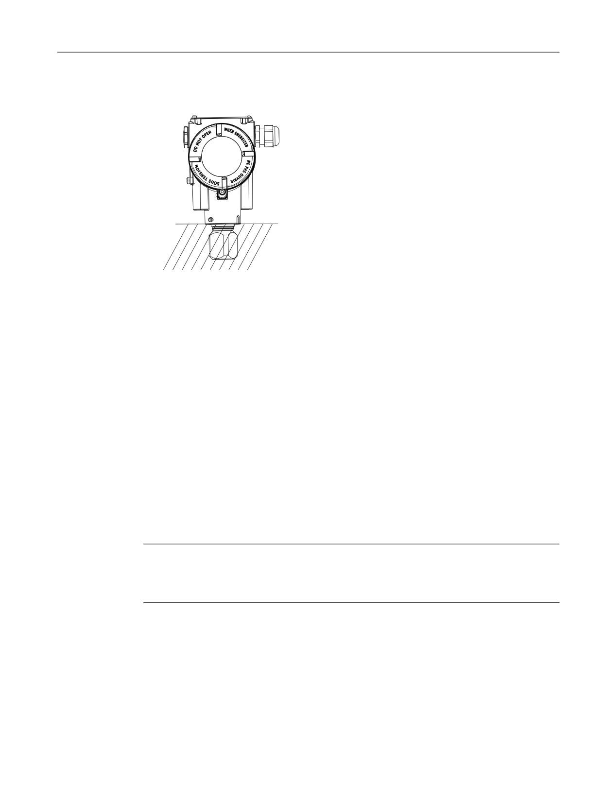
3. For insulated systems, ensure that you insulate the device as far as possible to the lower
edge of the enclosure:
0D[
In this way, you avoid a defect in the device or the loss of explosion protection for Ex devices.
You can find the permissible temperature values in the section Technical data (Page 199).
4. To guarantee secure and vibration-free installation of the pressure transmitter, fasten it to
a mounting bracket (Page 49).
5.2.2
Fastening with the mounting bracket
Introduction
You mount the pressure transmitter with the mounting bracket as described below:
● On a mounting range
● On a vertical or horizontal pipe (Ø 50 to 60 mm)
When securing, observe the torques in the section Torques (Page 238).
Note
Install the device so that the pressure transmitter and the differential pressure lines are not
subject to different vibrations. Otherwise there is a danger that the differential pressure lines will
rupture.
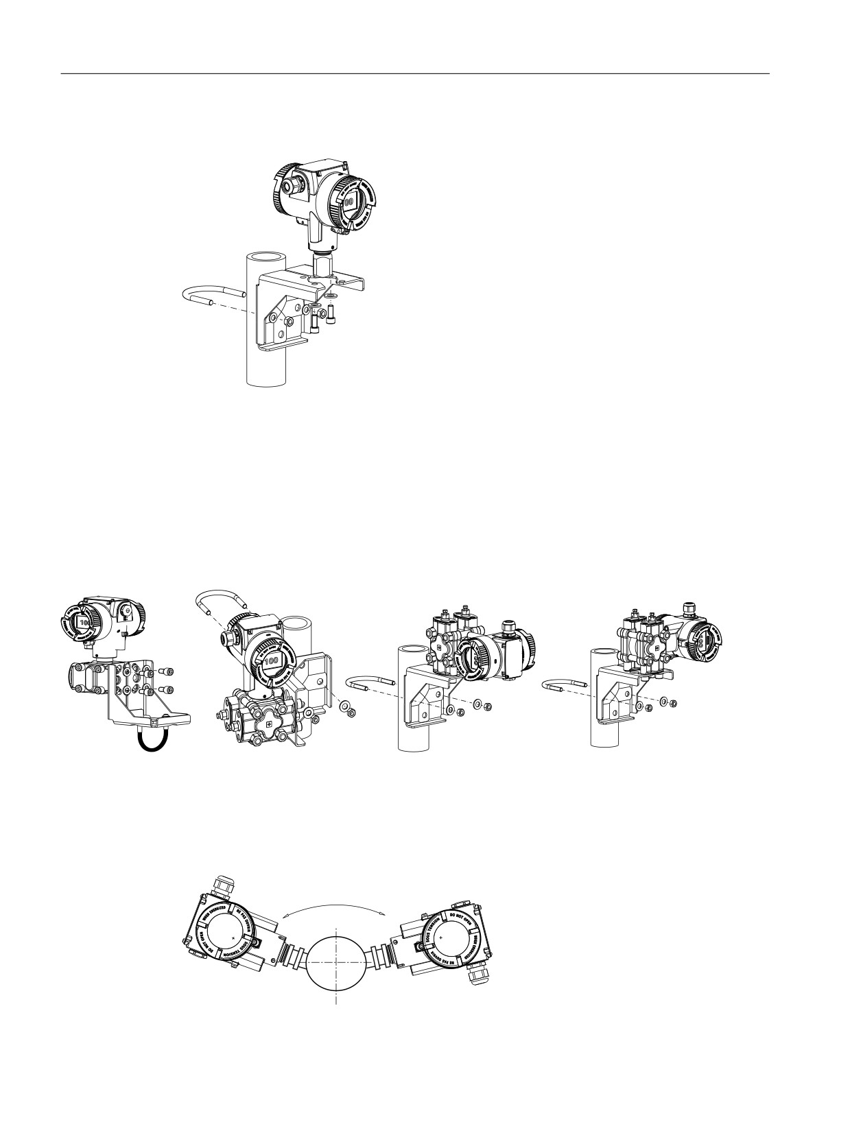
Example 1: Pipe mounting of pressure transmitter (gauge pressure series)
The mounting bracket for the gauge pressure series includes, among other things:
●
2 screws
● One pipe clamp with nuts
● Washers
SITRANS P320/P420 with 4 to 20 mA/HART
49
Installing/mounting
5.2 Installing
Mount the pressure transmitter as follows:
Example 2: Pipe mounting of pressure transmitter (differential pressure series)
The mounting bracket for the differential pressure series includes, among other things:
●
4 screws
● One pipe clamp with nuts
● Washers
You can then mount the pressure transmitter in different positions:
5.2.3
Mounting hygienic version
To avoid formation of steam, mount the pressure transmitter as follows, for example:
Figure 5-1
Correct installation
SITRANS P320/P420 with 4 to 20 mA/HART
50

Installing/mounting
5.3 Installation (level)
Figure 5-2
Incorrect installation
● Ensure that the length of the dead space at the end of the process connection is smaller than
its diameter.
● To ensure optimal cleaning of the process plant, install the process connection without
offset (flush-mounted on inside) in the plant.
You can find additional information in the EHEDG Guidelines No. 10 and No. 37.
5.3
Installation (level)
Mounting location
Verify that the mounting location meets the following conditions:
● Accessible
● Close to the measuring point
● Vibration-free
● Within the permitted ambient temperature values
Protect the pressure transmitter from:
● Direct heat radiation
● Rapid temperature fluctuations
● Heavy contamination
● Mechanical damage
● Direct sunlight
Note
Select the height of the mounting flange such that the pressure transmitter is always mounted
below the lowest fill height to be measured.
Requirement
● You have compared the desired operating data with the data on the nameplate.
● You have adhered to the information on the remote seal during its installation.
SITRANS P320/P420 with 4 to 20 mA/HART
51
Installing/mounting
5.3 Installation (level)
Procedure
To install the pressure transmitter for level, proceed as follows:
1. Attach the seal to the container's mating flange.
Ensure that the seal is centrally positioned and that it does not restrict the movement of the
flange's seal diaphragm in any way. Otherwise, the seal of the process connection is not
guaranteed to be tight.
2. Screw on the pressure transmitter's flange.
3. Observe the installation position.
5.3.1
Mounting on the container
Mounting on open container
A line is not required when taking measurements in an open container since the negative side
is connected with the atmosphere.
Ensure that no dirt enters the open connection ports.
● Use, for example, threaded plug with vent valve 7MF4997-1CP.
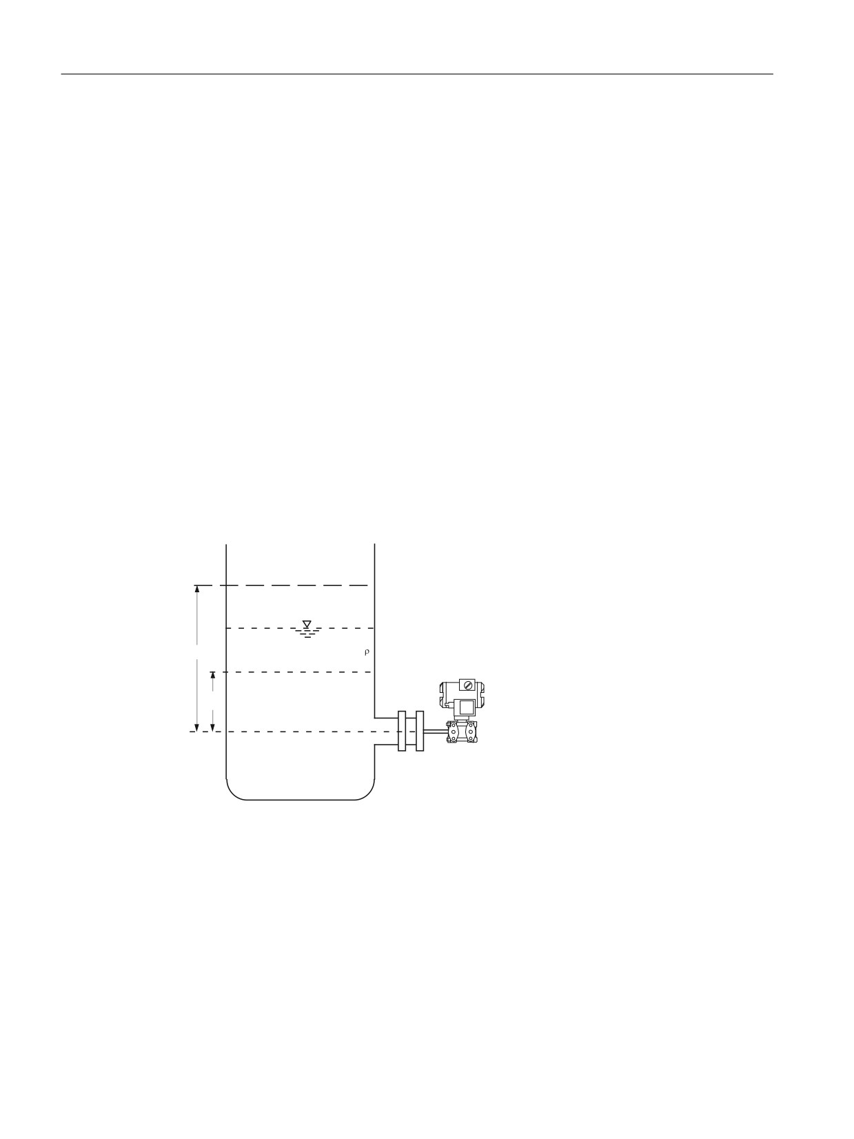
Formula:
8SSHU UDQJH YDOXH
Lower range value: pMA = ρ · g · hU
Upper range value: pME = ρ · g · hO
K2
/RZHU UDQJH YDOXH
K8
+
Measurement assembly on an open container
hU
Lower filling level
ΔpMA Lower range value
hO
Upper filling level
ΔpME Upper range value
p
Pressure
ρ
Density of the measured medium in
the container
g
Acceleration due to gravity
SITRANS P320/P420 with 4 to 20 mA/HART
52

Installing/mounting
5.3 Installation (level)
Mounting on closed container
When taking measurements in a closed container without or with little condensate formation,
the negative pressure line is not filled.
Lay the line in such a way that condensation pockets do not form. If required, you need to install
a condensation container below the negative pressure line of the pressure transmitter.
Formula:
*DV ILOOHG QHJDWLYH
Lower range value: ΔpMA = ρ · g · hU
SUHVVXUH OLQH
Upper range value: ΔpME = ρ · g · hO
0D[LPXP OHYHO
8SSHU UDQJH YDOXH
/RZHU UDQJH YDOXH
K
2
K8
3UHVVXUH WUDQVPLWWHU
UHIHUHQFH OLQH
Measurement assembly on a closed container (no or little
condensate separation)
hU
Lower filling level
ΔpMA Lower range value
hO
Upper filling level
ΔpME Upper range value
p
Pressure
ρ
Density of the measured medium in
the container
g
Acceleration due to gravity
When taking measurements in a closed container with strong condensate formation, you must
fill the negative pressure line (mostly with the condensate of the measured medium) and install
a condensate pot. Lock the device using the dual pneumatic block 7MF9017-..A.
SITRANS P320/P420 with 4 to 20 mA/HART
53

Installing/mounting
5.4 Installation with remote seal
To compensate the liquid column on the minus side, reset the zero point.
Formula:
&RQVWDQW
&RPSDULVRQ
Lower range value:
OHYHO
ΔpMA = g · (hU · ρ - hV · ρ')
0D[LPXP OHYHO
Upper range value:
ΔpMA = g · (hO · ρ - hV · ρ')
8SSHU UDQJH YDOXH
/LTXLG ILOOHG
QHJDWLYH SUHVVXUH OLQH
/RZHU UDQJH YDOXH
KY
'
K2
K8
3UHVVXUH WUDQVPLWWHU
-
UHIHUHQFH OLQH
Measurement assembly on a closed container (strong condensate
formation)
hU
Lower filling level
ΔpMA Lower range value
hO
Upper filling level
ΔpME Upper range value
hV
Gland distance
ρ
Density of the measured medium in
the container
p
Pressure
ρ '
Density of fluid in the negative pres-
sure line corresponds to the prevailing
temperature there
g
Acceleration due to gravity
The process connection on the negative side is a female thread 1/4-18 NPT or an oval flange.
Lay the line for the negative pressure using a seamless steel tube 12 mm x 1.5 mm.
5.4
Installation with remote seal
Notes
● Keep the measuring system in the factory packing until it is installed in order to protect it from
mechanical damage.
● When removing from the factory packing and installing: ensure that damage to and
mechanical deformations in the membrane are prevented.
● Never loosen the sealed filling screws on the remote seal and the measuring instrument.
SITRANS P320/P420 with 4 to 20 mA/HART
54
Installing/mounting
5.4 Installation with remote seal
●
Do not cause damage to the remote separating membrane; scratches on the remote
separating membrane, e.g. due to sharp-edged objects, are the main starting points for
corrosion.
●
Select suitable gaskets for sealing.
●
Use a gasket having an adequately large inner diameter for flanging. Insert the gasket
concentrically; contact with the membrane leads to deviations in measurements.
●
When using gaskets made of soft materials or PTFE: follow the guidelines of the gasket
manufacturer, especially regarding the tightening torque and setting cycles.
●
At the time of installation, use suitable fastening components such as screws and nuts that
are compliant with fitting and flange standards.
●
Excessive tightening of screwed joints on the process connection may displace the zero
point on the pressure transmitter.
Note
Commissioning
If a shut-off valve exists, open the shut-off valve slowly when commissioning in order to
avoid pressure surges.
Note
Permissible ambient and operating temperatures
Install the pressure measuring device such that the permissible limits of ambient and
measured medium temperatures are not overshot or undershot even with the consideration
of the effect of convection and heat radiation.
● Note the effect of temperature on the measuring accuracy.
● When selecting the remote seals, ensure that fittings and flange components have
adequate pressure-temperature resistance by selecting suitable materials and pressure
ratings. The pressure rating specified on the remote seal applies to reference conditions
according to IEC 60770.
● For the maximum permissible pressure at higher temperatures, please refer to the
standard specified on the remote seal.
Using remote seals with pressure measuring device for hazardous areas:
● When using remote seals with pressure transmitters in hazardous areas, the permissible
ambient temperature limits for the pressure transmitter must not be exceeded. Hot surfaces
on the cooling section (capillaries or cooling elements) are a possible source of ignition.
Initiate suitable measures.
● When remote seals with a flame arrestor are used, the pressure measuring instrument
determines the permissible ambient temperature. In the case of potentially explosive
gaseous atmosphere, the temperature around the flame arrestor must not exceed +60 °C.
SITRANS P320/P420 with 4 to 20 mA/HART
55

Installing/mounting
5.4 Installation with remote seal
5.4.1
Remote seal with capillary line
Notes
● Do not transport the measuring assembly (pressure transmitter, flange and capillary line) to
the capillary line.
● Do not bend the capillary lines. Otherwise there may be a leakage risk and the set-up time
of the measuring system is increased.
● A mechanical overload at the connection points between capillary line and remote seal or
between capillary line and pressure transmitter will lead to potential bending or breaking.
● Wind capillary lines that are too long with a radius of at least 300 mm.
● Fasten the capillary line such that there are no vibrations.
● Permissible height differences:
- In the case of remote seal measuring systems with silicon, glycerin or paraffin oil filling,
the height difference of H1max. = 7 m must not be exceeded.
- When halocarbon oil is used as fill fluid, the maximum height difference may only be
H1max. = 4 m; see installation type A and installation type B.
If a negative overpressure is observed during measurements, reduce the permissible height
difference.
Installation type for gauge pressure and level measurements (open containers)
Start of scale value:
pLRV = ρFL * g * HU - ρoil * g * H1
+
Full-scale value:
+R
pURV = ρFL * g * HO - ρoil * g * H
1
+X
+
Installation type A: Pressure transmitter
above the measuring point
SITRANS P320/P420 with 4 to 20 mA/HART
56

Installing/mounting
5.4 Installation with remote seal
Start of scale value:
pLRV = ρFL * g * HU + ρoil * g * H1
+
Full-scale value:
+R
pURV = ρFL * g * HO + ρoil * g * H
1
+X
+
Installation type B: Pressure transmitter
below the measuring point
H1 ≤ 7 m (23 ft); with halocarbon oil as the filling liquid, only H1 ≤ 4 m(13.1 ft)
Key
pLRV
Start of scale value
pURV
Full-scale value
ρFL
Density of the process medium in the container
ρoil
Density of the filling oil in the capillary line of the remote seal
g
Acceleration due to gravity
HU
Lower filling level
HO
Upper filling level
H1
Distance container flange to pressure transmitter
For absolute pressure measurements (vacuum), install the pressure transmitter at least at the
height of the remote seal or below it (see installation types C).
SITRANS P320/P420 with 4 to 20 mA/HART
57

Installing/mounting
5.4 Installation with remote seal
Installation types for absolute pressure measurements (closed containers)
Start of scale value:
pLRV = pstart + ρoil * g * H1
Full-scale value:
+
pURV = pend + ρoil * g * H1
SDEV
Installation type C1
Start of scale value:
pLRV = pstart + ρoil * g * H1
Full-scale value:
pURV = pend + ρoil * g * H1
SDEV
+
Installation type C2
Always install pressure transmitter for absolute pressure below the measuring point: H1 ≥
200 mm (7.9 inch)
Key
pLRV
Start of scale value
pURV
Full-scale value
pstart
Initial pressure in the container
pend
Final pressure in the container
ρoil
Density of the filling oil in the capillary line of the remote seal
g
Acceleration due to gravity
H1
Distance container flange to pressure transmitter
Note
Effects of temperature
Keep the following instructions in mind to minimize the effects of temperature in remote seal
measuring systems with differential pressure transmitter:
Install the device so that the positive and negative sides are symmetrical as far as ambient
effects and the ambient temperature are concerned.
SITRANS P320/P420 with 4 to 20 mA/HART
58
Installing/mounting
5.4 Installation with remote seal
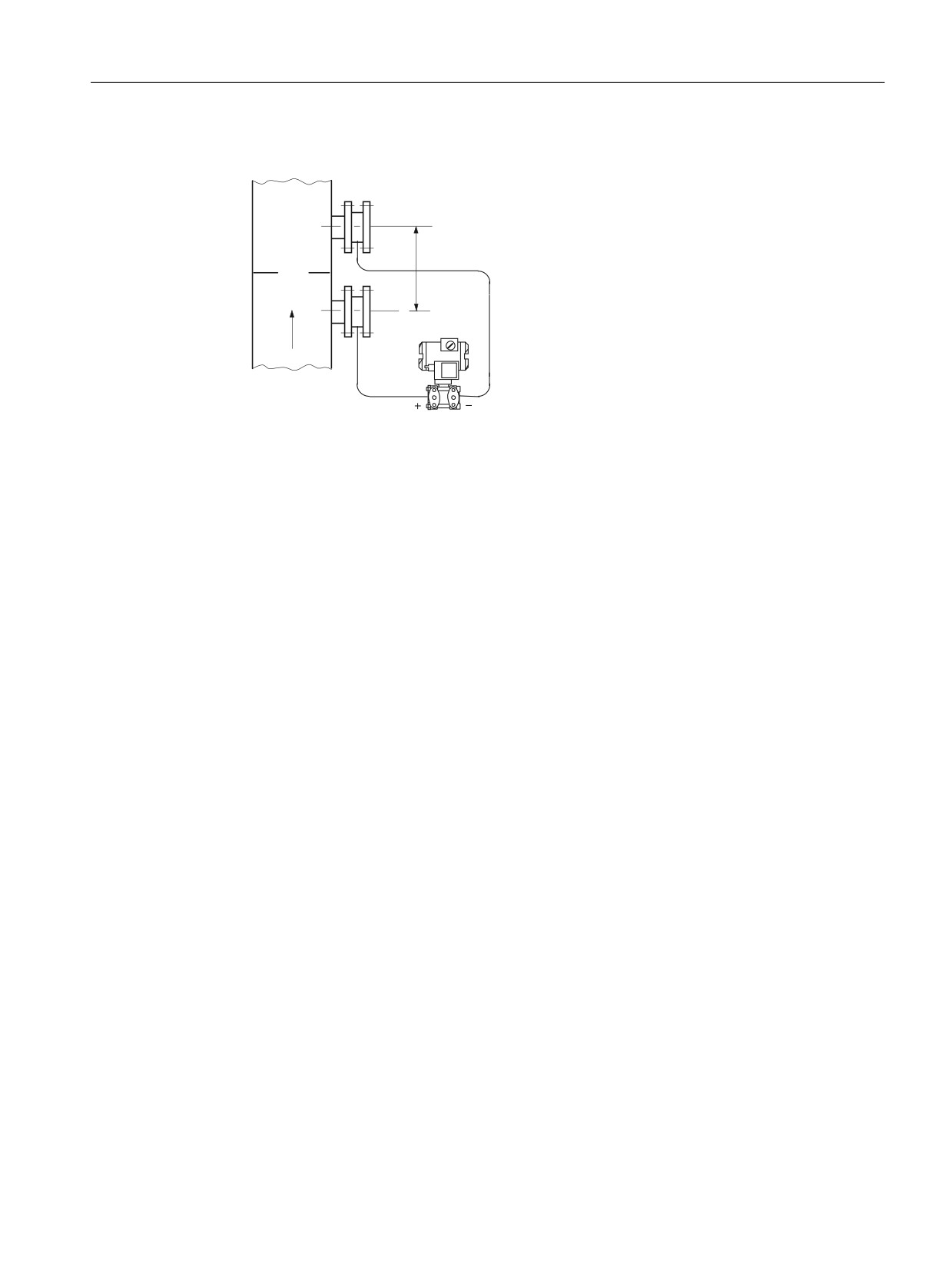
Installation type for differential pressure and flow rate measurements
Start of scale value:
pLRV = pstart - ρoil * g * HV
Full-scale value:
+9
pURV = pend - ρoil * g * HV
Installation type D
Key
pLRV
Start of scale value
pURV
Full-scale value
pstart
Initial pressure in the container
pend
Final pressure in the container
ρoil
Density of the filling oil in the capillary line of the remote seal
g
Acceleration due to gravity
HV
Gland distance
H1
Distance container flange to pressure transmitter
Installation types for level measurements (closed containers)
Reset the zero point after installation to compensate the liquid column on the minus side.
This measure applies to the following installation types:
SITRANS P320/P420 with 4 to 20 mA/HART
59

Installing/mounting
5.4 Installation with remote seal
H1 ≤ 7 m (23 ft), for halocarbon oil, however only H1
≤ 4 m (13.1 ft)
Start of scale value:
pLRV = ρFL * g * HU - ρoil * g * HV
Full-scale value:
pURV = ρFL * g * HO - ρoil * g * HV
+
+
+9
+R
+X
Installation type G
Pressure transmitter for differential
pressure above the upper measuring
point, no vacuum
Start of scale value:
pLRV = ρFL * g * HU - ρoil * g * HV
Full-scale value:
+
pURV = ρFL * g * HO - ρoil * g * HV
+9
+R
+X
Installation type H
Below the lower measuring point
H2 ≤ 7 m (23 ft); with halocarbon oil as the filling
liquid, only H2 ≤ 4 m(13.1 ft)
+
Start of scale value:
pLRV = ρFL * g * HU - ρoil * g * HV
+
+9
Full-scale value:
+R
+
pURV = ρFL * g * HO - ρoil * g * HV
+X
Installation type J
Between the measuring points, no
vacuum
SITRANS P320/P420 with 4 to 20 mA/HART
60
Installing/mounting
5.6 Rotating the display
Key
pLRV
Start of scale value
pURV
Full-scale value
ρFL
Density of the process medium in the container
ρoil
Density of the filling oil in the capillary line of the remote seal
g
Acceleration due to gravity
HU
Lower filling level
HO
Upper filling level
HV
Gland distance
H1/H2
Distance container flange to pressure transmitter
5.5
Installing electrical connections and cable entries
The device is delivered with dust caps installed on both sides at the factory.
You use the order options A.. to define the type of electrical connections and cable entries
(cable gland, sealing plug or device plug) for your device.
These components are delivered with the device.
● To order the device with installed electrical connections and cable entries, select an
additional order option A.. for the installation (e.g. device plug mounted on the right).
Procedure
For the first installation follow these steps:
1. Ensure that the seals are clean and undamaged.
2. To ensure the IP degree of protection and explosion protection of the pressure transmitter,
close the cable entries with a sealing plug, a cable gland or a device plug.
See also
Replacing electrical connections and cable entries (Page 185)
5.6
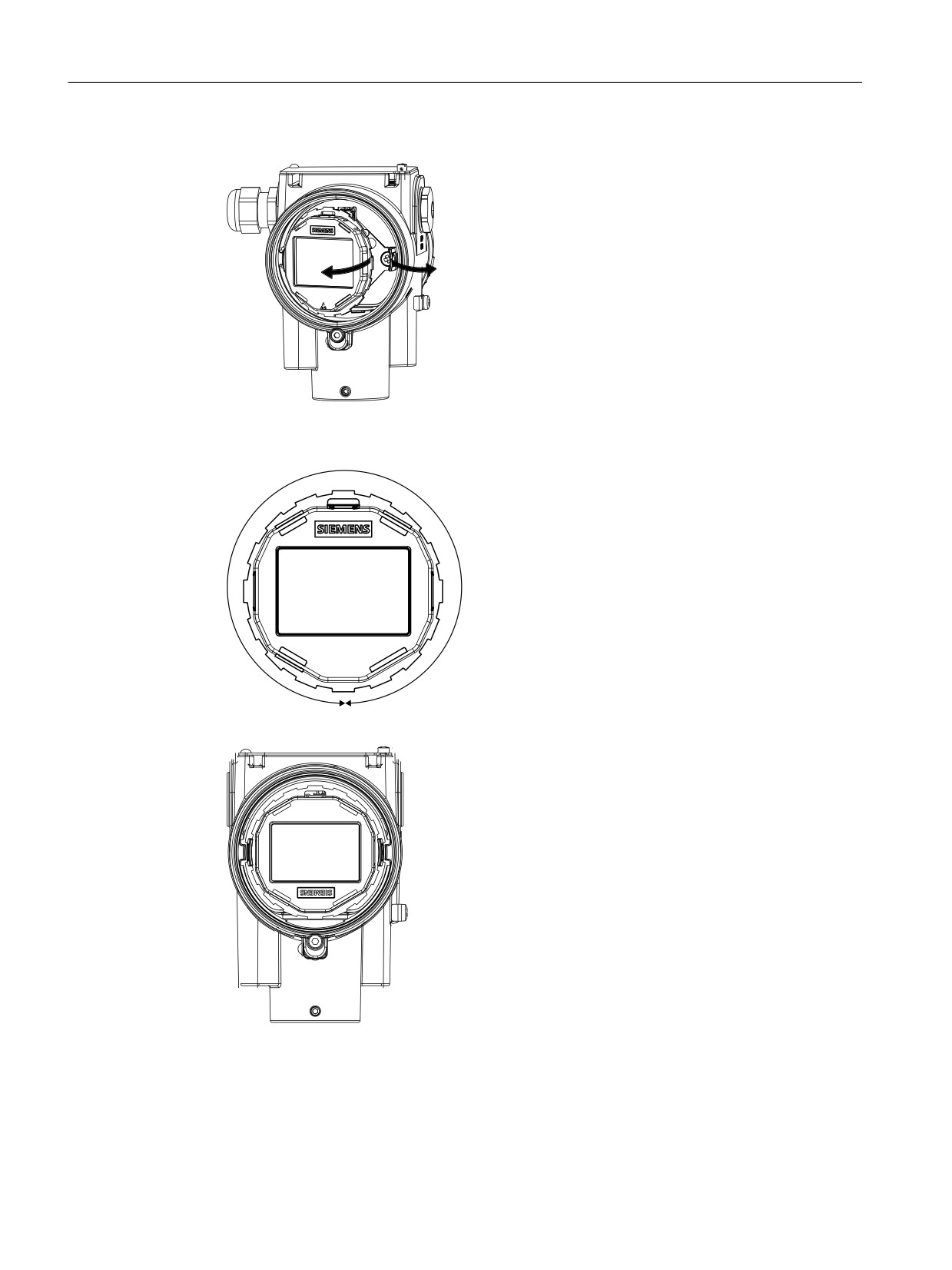
Rotating the display
To read the display in any mounting position, you have the option of gradually rotating the
display 360°.
Procedure
1. De-energize the device.
2. If available, loosen the front safety catch with a 3 mm Allen key.
3. Unscrew the front cover.
SITRANS P320/P420 with 4 to 20 mA/HART
61
Installing/mounting
5.6 Rotating the display
4. Remove the display from the holder.
5. Leave the display cable plugged into the electronics.
6. Rotate the display to the desired position.
7. Press the display into the holder until it engages.
SITRANS P320/P420 with 4 to 20 mA/HART
62

Installing/mounting
5.7 Rotating the enclosure
5.7
Rotating the enclosure
Introduction
To make the device easier to operate in any mounting position, you have the option of adjusting
the position of the enclosure within a range of 360°.
① Retaining screw
One retaining screw ① for the aluminum enclosure and two retaining screws (front and back)
for the stainless steel enclosure prevent that the flat ribbon cable is damaged while rotating the
enclosure.
The flat ribbon cable connects the sensor to the electronics.
The tightening torques of the retaining screws are different for the aluminum enclosure and the
stainless steel enclosure. For the tightening torques of the retaining screws, refer to section
Torques (Page 238).
Requirement
You have a 2.5 mm Allen key.
Rotating the aluminum enclosure
1. Loosen the retaining screw ① by half a rotation.
2. Rotate the enclosure to the desired position (but no further than the end stop).
3. Tighten the retaining screw.
SITRANS P320/P420 with 4 to 20 mA/HART
63
Installing/mounting
5.8 Removing
Rotating the stainless steel enclosure
1. Loosen the front retaining screw by half a rotation.
2. Loosen the back retaining screw by half a rotation.
3. Rotate the enclosure to the desired position (but no further than the end stop).
4. Tighten the front and back retaining screw.
To prevent the enclosure from turning in case of vibration, make sure that the front and back
retaining screw are tightened.
5.8
Removing
WARNING
Incorrect disassembly
The following risks may result from incorrect disassembly:
- Injury through electric shock
- Risk through emerging media when connected to the process
- Risk of explosion in hazardous area
In order to disassemble correctly, observe the following:
● Before starting work, make sure that you have switched off all physical variables such as
pressure, temperature, electricity etc. or that they have a harmless value.
● If the device contains hazardous media, it must be emptied prior to disassembly. Make
sure that no environmentally hazardous media are released.
● Secure the remaining connections so that no damage can result if the process is started
unintentionally.
SITRANS P320/P420 with 4 to 20 mA/HART
64
Connecting
6
6.1
Basic safety instructions
WARNING
Unsuitable cables, cable glands and/or plugs
Risk of explosion in hazardous areas.
● Use only cable glands/plugs that comply with the requirements for the relevant type of
protection.
● Tighten the cable glands in accordance with the torques specified in Technical data
(Page 199).
● Close unused cable inlets for the electrical connections.
● When replacing cable glands, only use cable glands of the same type.
● After installation, check that the cables are seated firmly.
WARNING
Incorrect conduit system
Risk of explosion in hazardous areas as result of open cable inlet or incorrect conduit system.
● In the case of a conduit system, mount a spark barrier at a defined distance from the device
input. Observe national regulations and the requirements stated in the relevant approvals.
WARNING
Unprotected cable ends
Risk of explosion through unprotected cable ends in hazardous areas.
● Protect unused cable ends in accordance with IEC/EN 60079-14.
SITRANS P320/P420 with 4 to 20 mA/HART
65

Connecting
6.1 Basic safety instructions
WARNING
Lack of equipotential bonding
Danger of explosion through compensating currents or ignition currents through lack of
equipotential bonding.
For devices of intrinsic safety "db", "ec", "tb" or "tc" which are operated in a non-intrinsically
safe circuit, observe the following:
● Connect the device to the system via the equipotential bonding terminal.
Note: For devices of the intrinsic safety "ia", "ib" and "ic" type of protection, which are operated
in an intrinsically safe circuit, connection to the system via the equipotential bonding terminal
is not required.
WARNING
Improper laying of shielded cables
Risk of explosion through compensating currents between hazardous area and the
non-hazardous area.
● Shielded cables that cross into hazardous areas should be grounded only at one end.
● If grounding is required at both ends, use an equipotential bonding conductor.
WARNING
Connecting device in energized state
Risk of explosion in hazardous areas.
● Connect devices in hazardous areas only in a de-energized state.
Exceptions:
● Devices having the type of protection "Intrinsic safety Ex i" may also be connected in
energized state in hazardous areas.
● Exceptions for type of protection "Increased safety ec" (Zone 2) are regulated in the
relevant certificate.
SITRANS P320/P420 with 4 to 20 mA/HART
66

Connecting
6.1 Basic safety instructions
WARNING
Incorrect selection of type of protection
Risk of explosion in hazardous areas.
This device is approved for various types of protection.
1. Select an intrinsic safety type of protection "ia", "ib", "ic" or non-intrinsic safety "db", "tb", "tc",
"ec".
2. Connect the device according to the selected type of protection.
3. When operating with non-intrinsically safe power supplies, make the intrinsically safe types
of protection permanently unrecognizable as in the example.
,,
* ([ LD ,,& 7
7
*D *E
,,
* ([ LD GE ,,& 7
7
*D *E
Figure 6-1
Nameplate example: Type 7MF0..0-
-.D..-Z + E20
NOTICE
Ambient temperature too high
Damage to cable sheath.
● At an ambient temperature ≥ 60 °C (140 °F), use heat-resistant cables suitable for an
ambient temperature at least 20 °C (36 °F) higher.
NOTICE
Condensation in the device
Damage to device through formation of condensation if the temperature difference between
transportation or storage and the mounting location exceeds 20 °C (36 °F).
● Before taking the device into operation, let the device adapt for several hours in the new
environment.
NOTICE
Incorrect measured values with incorrect grounding
The device must not be grounded using the "+" connection. It may otherwise malfunction and
be permanently damaged.
● If necessary, ground the device using the "-" connection.
SITRANS P320/P420 with 4 to 20 mA/HART
67

Connecting
6.2 Connecting the device
Note
Electromagnetic compatibility (EMC)
You can use this device in industrial environments, households and small businesses.
For metal housings there is an increased electromagnetic compatibility compared to high-
frequency radiation. This protection can be increased by grounding the housing, see Technical
data (Page 199).
Note
Improvement of interference immunity
● Lay signal cables separate from cables with voltages > 60 V.
● Use cables with twisted wires.
● Keep device and cables at a distance from strong electromagnetic fields.
● Take account of the conditions for communication specified in the Technical data
(Page 199).
● Use shielded cables to guarantee the full specification according to HART/PA/FF/Modbus/
EIA-485/Profibus DP.
6.2
Connecting the device
6.2.1
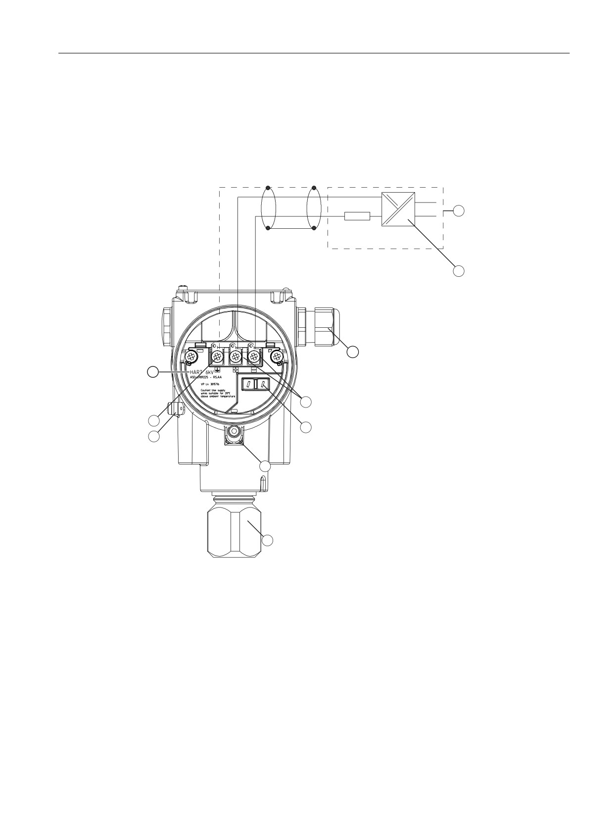
Opening the device
① Safety catch (optional)
② Cover of the electrical cable compartment.
Figure 6-2
Rear view of pressure transmitter
SITRANS P320/P420 with 4 to 20 mA/HART
68
Connecting
6.2 Connecting the device
1. Use a 3 mm Allen key to loosen the safety catch
①.
2. Unscrew the cover of the electrical cable compartment ②.
6.2.2
Connecting the device
˖
- Test +
① Supply unit with integrated load
⑥ Safety catch
② Supply voltage
⑦ Process connection
③ Cable gland
⑧ Protective conductor connector/
equipotential bonding terminal
④ Connecting terminals
⑨ Ground terminal
⑤ Test connector for DC measuring device
⑩ Devices with internal overvoltage
protection are marked here.
Figure 6-3
Example: Electrical connection with supply unit
SITRANS P320/P420 with 4 to 20 mA/HART
69

Connecting
6.2 Connecting the device
1. Connect the device to the system via the existing protective ground connection
⑧ by
observing the torques.
- Use a cable with a diameter of 1 … 4 mm2.
2. Insert the connecting cable through the cable gland ③.
3. Connect the wires to the connection terminals ④ "+" and "-", observing the polarity and the
torques.
- Use wires with a diameter of 0.5 ... 2.5 mm2.
- If you use stranded wire used, you need a ferrule.
4. Apply the shield to the screw of the ground terminal ⑨.
The screw of the ground terminal is electrically connected to the external protective
conductor connection.
NOTICE
Incorrect measured values with incorrect grounding
The device must not be grounded using the "+" connection. It may otherwise malfunction
and be permanently damaged.
● If necessary, ground the device using the "-" connection.
5. For devices with intrinsically safe protection type, use a supply unit that corresponds to the
requirements of the relevant type of protection.
See also
Torques (Page 238)
SITRANS P320/P420 with 4 to 20 mA/HART
70

Connecting
6.3 Connect the Han cable socket to the cable
6.2.3
Closing the device
① Cover over buttons
⑤ Blanking plug
② Cable gland
⑥ Safety catch (front)
③ Safety catch (back)
⑦ Cover (front)
④ Cover (rear) for electrical terminal compartment
Figure 6-4
View of the pressure transmitter: Left: Back right: Front view
1. Screw on the cover ④ and ⑦ as far as it will go.
Make sure that there is no gap between enclosure and cover.
2. Secure each cover with the cover catch ③ and ⑥ by removing the screw.
3. Close the cover over the buttons①.
4. Tighten the screw for the cover over the buttons.
6.3
Connect the Han cable socket to the cable
WARNING
Loss of the safety required for approval by using the Han plug
You may only use the Han plug for non-Ex devices; otherwise, the safety required for the
approval is not guaranteed.
Note
Observe the protection class of the Han plug when defining the protection class.
The contact parts for the cable socket are supplied.
For devices with a Han plug mounted on the enclosure, make the connection via the cable
socket.
SITRANS P320/P420 with 4 to 20 mA/HART
71

Connecting
6.4 Connect M12 cable socket to the cable
Requirement
● The terminal area of the cable socket is suitable for cables with diameters ranging from 6 to
12 mm.
● These cables use stranded wires with 1 mm2 as single conductors ("+", "-" and ground).
● You are using a crimping tool from HARTING (article number 09 99 000 0110).
Procedure
1. Slide the sleeve and the screwed joint on the cable.
2. Strip approx. 8 mm of the cable ends.
3. Crimp the contact parts on the cable ends.
4. Assemble the cable socket.
IA
Output current
UH
Auxiliary power
,$
8+
Connector pin assignment with Han 7D or
Han 8D plug or cable socket
6.4
Connect M12 cable socket to the cable
WARNING
Loss of safety required for approval by using the M12 device plug.
You may only use the plug for non-Ex devices; otherwise, the safety required for the approval
is not guaranteed.
Note
A conductive connection must not exist between the shield and the connector housing.
Note
Observe the protection class of the M12 device plug when defining the protection class.
In devices where a plug is already mounted on the enclosure, the connection is made via a
cable socket.
1. Thread the parts of the cable socket as described by the manufacturer of the cable socket.
2. Strip approximately 18 mm of the bus cable ①.
SITRANS P320/P420 with 4 to 20 mA/HART
72

Connecting
6.4 Connect M12 cable socket to the cable
3. Twist the shield.
4. Thread the shield in the insulating sleeve.
5. Draw 8 mm of shrink sleeve over the cable, wires and shield up to the reference edge ②.
6. Screw the cable ends and the shield in the pin insert.
7. Fasten the parts of the cable socket as described by the manufacturer.
Figure 6-5
Preparing the connecting cable
① Reference edge for stripping
③ Insulating sleeve over the shield
② Reference edge for the dimension
④ Shrink sleeve
specifications for cable assembly
Assignment
Layout for M12 device plug
Assignment diagram M12-cable socket
① M12 x 1 thread
① Positioning slot
② Positioning catch
1
+
1
+
2
Not connected
2
Not connected
3
-
3
-
SITRANS P320/P420 with 4 to 20 mA/HART
73
Connecting
6.4 Connect M12 cable socket to the cable
4
Shield
4
Shield
Middle contact of the cable socket not
connected
SITRANS P320/P420 with 4 to 20 mA/HART
74
Operating
7
Introduction
You operate the device using the buttons.
If you have a device with a display, you can view the measured values, parameter values and
messages.
If you have a device without a display, you also have several functions available:
Commissioning the device without display (Page 89)
7.1
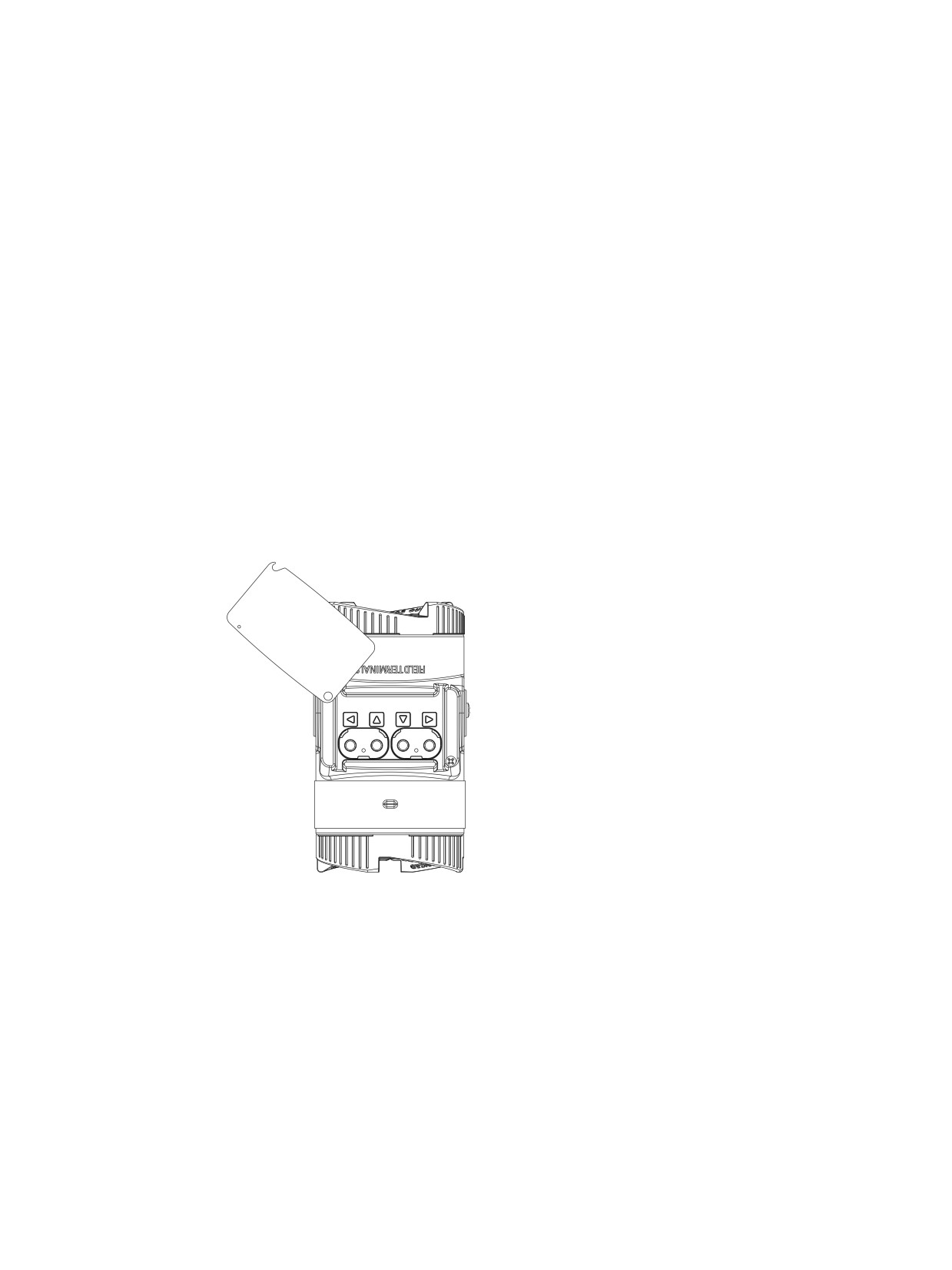
Buttons
The four buttons are located below the cover:
Figure 7-1
Top view
SITRANS P320/P420 with 4 to 20 mA/HART
75

Operating
7.2 Operating the device with display
7.2
Operating the device with display
7.2.1
Navigating in the views
You navigate in the views with the Buttons (Page 75) buttons:
Views
Buttons
Measurement view After the initialization, the measurement view is displayed.
1. Select a random measured value with the buttons
or
2. Change to the parameter view with the
button.
3. Return to the measurement view with the
button.
Parameter view
The "EDIT" symbol has been activated permanently.
1. Select a parameter with the buttons
or
2. Change to the edit view with the button
3. Return to the measurement view with the
button.
Edit view
The "EDIT" symbol flashes.
1. Change the parameter value with the
or
button.
2. Save the change with the button
You are in the parameter view.
3. Return to the measurement view with the
button.
If you do not change any parameters, you return from the edit view to the param-
eter view with the
button.
7.2.2
Measurement view
The measurement view shows the current measured values as well as status and diagnostic
messages:
① Name and unit of the measured value (alternating)
② Measured value
③ Measured value ID
④ Bar display
Figure 7-2
Example of measurement view
① shows the name of the measured value and the set unit as alternating values.
Measured value IDs ③ start with "P".
SITRANS P320/P420 with 4 to 20 mA/HART
76

Operating
7.2 Operating the device with display
The bar display shows the following information:
● The position of a measured value within the set measuring span (e.g. pressure).
● The position of the temperature value within the sensor limits.
● The scaling of the process values calculated from the pressure value (e.g. volume flow).
7.2.2.1
Display of measured values
The following measured values are always displayed:
● Pressure (P1)
● Sensor temperature (P2)
● Electronics temperature (P3)
● Percent of range (P9)
● Loop current (PA)
● Terminal voltage (PB)
The following values are calculated from the measured pressure value and are displayed
depending on your application:
● Level (P4)
● Volume (P5)
● Volume flow (P6)
● Mass flow (P7)
● Customized characteristic curve (P8)
Measured val-
Name of measured value
Meaning
ue ID
P1
PRESSURE
Pressure
PRESS GAUGE
Gauge pressure
PRESS ABS
Absolute pressure
P2
SENSOR TEMP
Sensor temperature
P3
ELECTR TEMP
Electronics temperature
P4
LEVEL
Level
P5
VOLUME
Volume
P6
VOLUME FLOW
Volume flow
P7
MASS FLOW
Mass flow
P8
USER DEFINED
Customized characteristic curve
P9
% OF RANGE
Percent of range
PA
LOOP CURRENT
Loop current
PB
CURR VOLTAGE
Terminal voltage
You use the "Start view" parameter [32] to select the measured value that is displayed as the
first measured value in the measurement view.
Start view [32] (Page 142)
SITRANS P320/P420 with 4 to 20 mA/HART
77

Operating
7.2 Operating the device with display
7.2.2.2
Navigating in the measurement view
Requirement
You have disabled the button lock.
Disabling button lock (Page 135)
Procedure
1. Use the
and buttons to navigate in the measurement view.
2. To switch to the parameter view, press the
button.
7.2.3
Parameter view
The parameter view shows the parameters, parameter values and the wizards of the device.
① Name and unit of the parameter (alternating)
② Parameter value
③ Parameter ID
④ "EDIT" symbol (permanently enabled)
Figure 7-3
Example of parameter view
For parameters with an associated unit, the parameter name and unit are displayed as
alternating values in ①. Example: Lower range value in mA.
7.2.3.1
List of parameters on the display
The parameters are displayed with parameter ID and parameter name.
Depending on the parameter settings of your device, some parameters are not visible.
Parame-
Parameter name on
Meaning
ter ID
the display
01
PRESS UNITS
Pressure units (Page 106)
02
LOWER RANGE
Set lower range value (without pressure applied) (Page 108)
03
UPPER RANGE
Set upper range value (without pressure applied) (Page 108)
04
DAMPING
Damping value (Page 110)
05
APPLICATION
Application 1) (Page 110)
SITRANS P320/P420 with 4 to 20 mA/HART
78
Operating
7.2 Operating the device with display
Parame-
Parameter name on
Meaning
ter ID
the display
06
SQRT POINT
Application point for volume flow and mass flow (VSLN and MSLIN) (Page 119)
07
ZERO POINT
Zero point adjustment (Page 119)
08
APPLY LRV
Apply lower range value (with pressure applied) (Page 122)
09
APPLY URV
Apply upper range value (with pressure applied) (Page 122)
10
FAULT CURR
Select fault current (Page 124)
11
LO FAULT CUR
Lower fault current (Page 124)
12
UP FAULT CUR
Upper fault current (Page 125)
13
SATURAT LOW
Lower saturation limit (Page 125)
14
SATURAT HIGH
Upper saturation limit (Page 126)
15
SV SELECT
SV selection, set secondary variable (Page 127)
16
LEVEL UNITS
Level unit (Page 127)
16
VOL UNITS
Volume units (Page 127)
16
VFLOW UNITS
Volume flow units (Page 127)
16
MFLOW UNITS
Mass flow units (Page 127)
17
TEMP UNITS
Temperature units for sensor and electronics temperature (Page 130)
18
LOWER SCALNG
Lower scaling point (Page 130)
19
UPPER SCALNG
Upper scaling point (Page 132)
20
LOW FLOW CUT
Low flow cut-off for volume flow and mass flow (VSOFF and MSOFF) (Page 132)
21
VESSEL DIM A
Vessel dimension A (Page 133)
22
VESSEL DIM L
Vessel dimension L (Page 134)
23
BUTTON LOCK
Enable and disable button lock (Page 134)
24
CHANGE PIN
Change user PIN (Page 135)
25
RECOVERY ID
Display Recovery ID (Page 136)
26
PIN RECOVERY
PIN recovery (Page 137)
27
USER PIN
Enable and disable user PIN (Page 138)
28
DEVICE MODE
Active device mode (Page 140)
29
FUNCT SAFETY
Enable and disable Functional Safety (Page 140)
30
DISPLAY TEST
Display test (Page 141)
31
LOOP TEST
Loop test (Page 141)
32
START VIEW
Start view (Page 142)
33
PRESSURE REF
Pressure reference (Page 143)
34
IDENTIFY
Identify the device (Page 143)
35
RESET
Reset (Page 143)
36
OVERLD BEHAV
Overload behavior (Page 145)
1) The "Application" parameter is also called the "Transfer function" in certain configuration
tools.
Hereinafter, the parameter ID is always written inside parentheses after the parameter name.
Example: Parameter "Damping value" [04].
See also
Parameter assignment over device with display (Page 106)
SITRANS P320/P420 with 4 to 20 mA/HART
79