Siemens SITRANS P. Operating Instructions (2019) - page 1

1
Getting Started
Introduction
2
3
Safety information
4
SITRANS P
Description
5
Installing/mounting
Pressure transmitter
6
Connecting
SITRANS P320/P420 with 4 to 20
mA/HART
7
Operating
Commissioning
8
Operating Instructions
9
Parameter assignment
10
Functional Safety
11
Service and maintenance
Diagnostics and
12
troubleshooting
13
Technical data
Dimension drawings
14
Product documentation and
A
support
B
Remote operation
Checklist for Functional
C
Safety
D
Sealing plug / thread adapter
E
Abbreviations
7MF03..-
-
(SITRANS P320)
7MF04..-
-
(SITRANS P420)
11/2019
A5E44852162-AC

Legal information
Warning notice system
This manual contains notices you have to observe in order to ensure your personal safety, as well as to prevent
damage to property. The notices referring to your personal safety are highlighted in the manual by a safety alert
symbol, notices referring only to property damage have no safety alert symbol. These notices shown below are
graded according to the degree of danger.
DANGER
indicates that death or severe personal injury will result if proper precautions are not taken.
WARNING
indicates that death or severe personal injury may result if proper precautions are not taken.
CAUTION
indicates that minor personal injury can result if proper precautions are not taken.
NOTICE
indicates that property damage can result if proper precautions are not taken.
If more than one degree of danger is present, the warning notice representing the highest degree of danger will be
used. A notice warning of injury to persons with a safety alert symbol may also include a warning relating to property
damage.
Qualified Personnel
The product/system described in this documentation may be operated only by personnel qualified for the specific
task in accordance with the relevant documentation, in particular its warning notices and safety instructions. Qualified
personnel are those who, based on their training and experience, are capable of identifying risks and avoiding
potential hazards when working with these products/systems.
Proper use of Siemens products
Note the following:
WARNING
Siemens products may only be used for the applications described in the catalog and in the relevant technical
documentation. If products and components from other manufacturers are used, these must be recommended or
approved by Siemens. Proper transport, storage, installation, assembly, commissioning, operation and
maintenance are required to ensure that the products operate safely and without any problems. The permissible
ambient conditions must be complied with. The information in the relevant documentation must be observed.
Trademarks
All names identified by ® are registered trademarks of Siemens AG. The remaining trademarks in this publication
may be trademarks whose use by third parties for their own purposes could violate the rights of the owner.
Disclaimer of Liability
We have reviewed the contents of this publication to ensure consistency with the hardware and software described.
Since variance cannot be precluded entirely, we cannot guarantee full consistency. However, the information in this
publication is reviewed regularly and any necessary corrections are included in subsequent editions.
Siemens AG
Document order number: A5E44852162
Digital Industries
Ⓟ 10/2019 Subject to change
All rights reserved
Postfach 48 48
90026 NÜRNBERG
GERMANY
Table of contents
1
Getting Started
11
1.1
Commissioning the device without display
11
1.2
Commissioning the device with display
12
2
Introduction
15
2.1
Purpose of this documentation
15
2.2
Scope of validity of this document
15
2.3
Document history
15
2.4
Product compatibility
16
2.5
Checking the consignment
16
2.6
Security information
16
2.7
Transportation and storage
17
2.8
Notes on warranty
17
3
Safety information
19
3.1
Precondition for use
19
3.1.1
Warning symbols on the device
19
3.1.2
Laws and directives
19
3.1.3
Conformity with European directives
20
3.1.4
Classification according to the pressure equipment directive
20
3.2
Requirements for special applications
21
3.3
Use in hazardous areas
21
4
Description
25
4.1
Area of application
25
4.2
Structure
27
4.3
Nameplate layout
28
4.4
Functional principle
30
4.4.1
Electronics
31
4.4.2
Measuring cell
32
4.4.2.1
Measuring cell for gauge pressure
33
4.4.2.2
Measuring cell for gauge pressure, front-flush membrane
34
4.4.2.3
Measuring cell for absolute pressure from the gauge pressure series
34
4.4.2.4
Measuring cell for absolute pressure, front-flush membrane
35
4.4.2.5
Measuring cell for absolute pressure from the differential pressure series
36
4.4.2.6
Measuring cell for differential pressure and flow rate
37
4.4.2.7
Measuring cell for level
38
4.5
System configuration
38
SITRANS P320/P420 with 4 to 20 mA/HART
3
Table of contents
4.6
Remote seal and differential pressure flow measuring systems
40
4.6.1
Remote seal
40
4.6.2
Differential pressure - flow measuring systems
40
4.6.3
Remote seals and primary element for devices with functional safety
41
5
Installing/mounting
43
5.1
Basic safety instructions
43
5.1.1
Installation location requirements
46
5.1.1.1
Use in maritime deployment
46
5.1.2
Proper mounting
47
5.2
Installing
47
5.2.1
Introduction
47
5.2.2
Fastening with the mounting bracket
49
5.2.3
Mounting hygienic version
50
5.3
Installation (level)
51
5.3.1
Mounting on the container
52
5.4
Installation with remote seal
54
5.4.1
Remote seal with capillary line
56
5.5
Installing electrical connections and cable entries
61
5.6
Rotating the display
61
5.7
Rotating the enclosure
63
5.8
Removing
64
6
Connecting
65
6.1
Basic safety instructions
65
6.2
Connecting the device
68
6.2.1
Opening the device
68
6.2.2
Connecting the device
69
6.2.3
Closing the device
71
6.3
Connect the Han cable socket to the cable
71
6.4
Connect M12 cable socket to the cable
72
7
Operating
75
7.1
Buttons
75
7.2
Operating the device with display
76
7.2.1
Navigating in the views
76
7.2.2
Measurement view
76
7.2.2.1
Display of measured values
77
7.2.2.2
Navigating in the measurement view
78
7.2.3
Parameter view
78
7.2.3.1
List of parameters on the display
78
7.2.3.2
Navigating in the parameter view
80
7.2.4
Edit view
80
7.2.4.1
Changing parameter values
81
7.2.5
Symbols for information messages
81
7.3
Remote operation
81
SITRANS P320/P420 with 4 to 20 mA/HART
4
Table of contents
7.4
Locking the device
82
7.4.1
Enable write protection with jumper
82
7.4.2
Enable user PIN
83
7.4.3
Enabling button lock
84
8
Commissioning
87
8.1
Basic safety instructions
87
8.2
Switching on the supply voltage
88
8.3
Commissioning the device without display
89
8.4
Commissioning the device with display
90
8.5
Application examples
92
8.5.1
Gauge pressure, absolute pressure from differential pressure series, and absolute
pressure from gauge pressure series
92
8.5.1.1
Commissioning in gaseous environments
92
8.5.1.2
Commissioning with steam or liquid
93
8.5.2
Differential pressure and flow rate
94
8.5.2.1
Commissioning in gaseous environments
94
8.5.2.2
Commissioning for liquids
96
8.5.2.3
Commissioning with vapor
98
9
Parameter assignment
101
9.1
Overview of parameters and functions
101
9.2
Parameter assignment over device with display
106
9.2.1
Pressure units [01]
106
9.2.1.1
Display of the pressure units
107
9.2.1.2
Setting the pressure units
107
9.2.2
Set lower range value [02]/Set upper range value [03]
108
9.2.2.1
Set lower range value parameter [02]
108
9.2.2.2
Set upper range value parameter [03]
108
9.2.2.3
Set lower range value/upper range value (without pressure available)
109
9.2.3
Damping value [04]
110
9.2.3.1
Set damping value
110
9.2.4
Application [05]
110
9.2.4.1
Pressure measurement
112
9.2.4.2
Level measurement
113
9.2.4.3
Volume and mass flow measurements
115
9.2.4.4
Volume measurement
118
9.2.4.5
Set application
119
9.2.5
Application point [06]
119
9.2.6
Zero point adjustment [07]
119
9.2.6.1
Adjusting zero point (gauge pressure)
120
9.2.6.2
Adjusting the zero point (differential pressure)
121
9.2.6.3
Adjusting zero point (absolute pressure)
121
9.2.7
Apply lower range value [08]/Apply upper range value [09]
122
9.2.7.1
Apply lower range value parameter [08]
122
9.2.7.2
Apply upper range value parameter [09]
122
9.2.7.3
Apply lower range value/upper range value (with pressure present)
122
9.2.8
Select fault current [10]
124
9.2.9
Lower fault current [11]
124
SITRANS P320/P420 with 4 to 20 mA/HART
5
Table of contents
9.2.10
Upper fault current [12]
125
9.2.11
Lower saturation limit [13]
125
9.2.12
Upper saturation limit [14]
126
9.2.13
SV selection [15]
127
9.2.14
Units [16]
127
9.2.14.1
Level units [16]
128
9.2.14.2
Volume units [16]
128
9.2.14.3
Volume flow units [16]
128
9.2.14.4
Mass flow units [16]
129
9.2.15
Temperature units [17]
130
9.2.16
Lower scaling point [18]
130
9.2.16.1
Set lower scaling point
131
9.2.17
Upper scaling point [19]
132
9.2.17.1
Set upper scaling point
132
9.2.18
Low flow cut-off [20]
132
9.2.19
Vessel dimension A [21]
133
9.2.20
Vessel dimension L [22]
134
9.2.21
Button lock [23]
134
9.2.21.1
Enabling button lock
134
9.2.21.2
Disabling button lock
135
9.2.22
Change user PIN [24]
135
9.2.23
Recovery ID [25]
136
9.2.23.1
Display Recovery ID
137
9.2.24
PIN recovery [26]
137
9.2.24.1
Recovering the user PIN
137
9.2.25
User PIN [27]
138
9.2.25.1
Enable user PIN
139
9.2.25.2
Disable user PIN
139
9.2.26
Active device mode [28]
140
9.2.27
Functional Safety [29]
140
9.2.28
Display test [30]
141
9.2.29
Loop test [31]
141
9.2.29.1
Loop test with preset loop current value
141
9.2.29.2
Loop test with user defined loop current value
142
9.2.30
Start view [32]
142
9.2.31
Pressure reference [33]
143
9.2.32
Identify the device [34]
143
9.2.33
Reset [35]
143
9.2.33.1
Reset to sensor calibration
144
9.2.33.2
Reset DAC trim to the factory setting
144
9.2.33.3
Restore ordered configuration
144
9.2.33.4
Restore factory settings
144
9.2.34
Overload behavior [36]
145
9.3
Parameter assignment over remote operation
145
9.3.1
Introduction
145
9.3.2
Quick start
146
9.3.3
Identification
146
9.3.4
Simulation
147
9.3.4.1
Simulate constant pressure values
147
9.3.4.2
Simulate ramp function
148
9.3.4.3
Simulate diagnostics
148
9.3.5
Customized characteristic curve
149
SITRANS P320/P420 with 4 to 20 mA/HART
6
Table of contents
9.3.5.1
Introduction
149
9.3.5.2
"Custom units" parameter
150
9.3.5.3
Set customized characteristic curve
150
9.3.6
Sensor calibration
151
9.3.7
Digital-to-analog converter trim (DAC trim)
152
9.3.8
Diagnostics functions
154
9.3.8.1
Limit monitoring and event counter
154
9.3.8.2
Trend log
157
9.3.8.3
Operating hours counter
158
10
Functional Safety
159
10.1
Safety concept
159
10.1.1
Random and systematic errors
159
10.1.2
SIL-compliant product version
159
10.1.3
Safety function
160
10.1.3.1
Device states
162
10.1.3.2
Safety characteristic values
162
10.1.4
Operating modes of the device
163
10.1.5
Device mode
163
10.1.5.1
Validation
164
10.1.5.2
Safety-related parameters
165
10.1.5.3
Device mode "Functional Safety enabled"
165
10.2
Enabling Functional Safety
166
10.2.1
Enabling Functional Safety over device with display
167
10.2.2
Enabling Functional Safety over remote operation
170
10.3
Acknowledging safety-related errors
174
10.3.1
"Safety critical error" device mode
174
10.3.2
Acknowledging safety-related errors via remote operation
175
10.4
Disabling Functional Safety over device with display
176
10.5
Disabling Functional Safety over remote operation
177
10.6
Proof test
178
10.6.1
Intervals and rules for proof test
178
10.6.2
Documenting a proof test
179
10.7
Repair and service
179
11
Service and maintenance
181
11.1
Basic safety instructions
181
11.2
Cleaning
182
11.2.1
Cleaning the enclosure
182
11.2.2
Servicing the remote seal measuring system
182
11.3
Maintenance and repair work
182
11.3.1
Checking the seals
184
11.3.2
Check cable glands
185
11.3.3
Replacing spare parts
185
11.3.3.1
Replacing electrical connections and cable entries
185
11.3.3.2
Replacing the display
185
11.3.3.3
Replacing the termination board
187
11.4
Return procedure
188
SITRANS P320/P420 with 4 to 20 mA/HART
7
Table of contents
11.5
Disposal
188
12
Diagnostics and troubleshooting
189
12.1
Device status symbols
189
12.2
Diagnostic messages
192
12.3
Troubleshooting
197
13
Technical data
199
13.1
Input
199
13.1.1
Gauge pressure
199
13.1.2
Gauge pressure with front-flush diaphragm
200
13.1.3
Gauge pressure from the differential pressure series
201
13.1.4
Absolute pressure from the gauge pressure series
202
13.1.5
Absolute pressure with front-flush diaphragm
203
13.1.6
Absolute pressure from the differential pressure series
204
13.1.7
Differential pressure and flow
206
13.1.8
Level
207
13.2
Measuring accuracy of SITRANS P320
208
13.2.1
Reference conditions
208
13.2.2
Effect of auxiliary power supply
208
13.2.3
Gauge pressure
208
13.2.4
Gauge pressure from the differential pressure series
210
13.2.5
Absolute pressure from gauge and differential pressure series
211
13.2.6
Absolute pressure with front-flush diaphragm
212
13.2.7
Gauge pressure with front-flush diaphragm
213
13.2.8
Differential pressure and flow
214
13.2.9
Level
217
13.3
Measuring accuracy of SITRANS P420
218
13.3.1
Reference conditions
218
13.3.2
Effect of auxiliary power supply
218
13.3.3
Gauge pressure
218
13.3.4
Gauge pressure from the differential pressure series
219
13.3.5
Absolute pressure from gauge and differential pressure series
221
13.3.6
Absolute pressure with front-flush diaphragm
222
13.3.7
Gauge pressure with front-flush diaphragm
223
13.3.8
Differential pressure and flow
223
13.3.9
Level
227
13.4
Output
228
13.5
Operating conditions
228
13.6
Vibration resistance
233
13.7
Construction
234
13.8
Torques
238
13.9
Display, keys and auxiliary power
238
13.10
Certificates and approvals
239
SITRANS P320/P420 with 4 to 20 mA/HART
8
Table of contents
14
Dimension drawings
243
14.1
SITRANS P320/P420 for gauge pressure and absolute pressure from the gauge
pressure series
243
14.2
SITRANS P320/P420 for differential pressure, gauge pressure, flow and absolute
pressure from the differential pressure series
245
14.3
SITRANS P 320/P420 for level
247
14.4
SITRANS P320/P420 (front-flush)
248
14.4.1
Note 3A and EHDG
249
14.4.2
Connections as per EN and ASME
249
14.4.3
F&B and pharma flange
250
14.4.4
PMC Style
254
14.4.5
Special connections
255
A
Product documentation and support
257
A.1
Product documentation
257
A.2
Technical support
258
B
Remote operation
259
B.1
SIMATIC PDM
259
B.1.1
Overview SIMATIC PDM
259
B.1.2
Check SIMATIC PDM version
259
B.1.3
Deactivate buffers when connecting via serial modem
260
B.1.4
Updating the Electronic Device Description (EDD)
261
C
Checklist for Functional Safety
263
D
Sealing plug / thread adapter
267
D.1
Intended use of accessory part
267
D.2
Safety instructions for accessory part
267
D.3
Technical specifications of accessory part
268
D.4
Dimensional drawings for accessory part
269
E
Abbreviations
271
Glossary
273
Index
277
SITRANS P320/P420 with 4 to 20 mA/HART
9
Table of contents
SITRANS P320/P420 with 4 to 20 mA/HART
10
Getting Started
1
1.1
Commissioning the device without display
Introduction
In this section, you will learn how to commission the device step-by-step.
Before you start, please read the following safety information:
● General safety information (Page 19)
● Basic safety information: Installing/mounting (Page 43)
● Basic safety information: Connecting (Page 65)
● Basic safety information: Commissioning (Page 87)
Read the entire device manual in order to achieve the optimum performance of the device.
Procedure
1. Mount the device.
Installing
(Page 47)
Installation (level) (Page 51)
2. Connect the device.
Connecting the device (Page 68)
3. Switch on the supply voltage.
Switching on the supply voltage (Page 88)
SITRANS P320/P420 with 4 to 20 mA/HART
11

Getting Started
1.2 Commissioning the device with display
4. Open the cover of the buttons:
Figure 1-1
Top view
5. Operate the buttons as follows:
Apply lower range value (with pressure applied)
Hold down the button
for 3 seconds.
Apply upper range value (with pressure applied)
Hold down the button
for 3 seconds.
Zero point adjustment
Hold down the buttons
and for 3 seconds.
Set Upper fault current
Hold down the button
for 3 seconds.
Set Lower fault current
Hold down the button
for 3 seconds.
Further functions are available via remote operation (e.g. SIMATIC PDM).
1.2
Commissioning the device with display
Introduction
In this section, you will learn how to commission the device step-by-step.
Before you start, please read the following safety information:
● General safety information (Page 19)
● Basic safety information: Installing/mounting (Page 43)
● Basic safety information: Connecting (Page 65)
● Basic safety information: Commissioning (Page 87)
Read the entire device manual in order to achieve the optimum performance of the device.
SITRANS P320/P420 with 4 to 20 mA/HART
12

Getting Started
1.2 Commissioning the device with display
Procedure
1. Mount the device.
Installing
(Page 47)
Installation (level) (Page 51)
2. Connect the device.
Connecting the device (Page 68)
3. Switch on the supply voltage.
Switching on the supply voltage (Page 88)
4. Open the cover of the buttons:
Figure 1-2
Top view
5. Set the measuring range.
Set lower range value/upper range value (without pressure available) (Page 109)
Apply lower range value/upper range value (with pressure present) (Page 122)
6. Set the pressure unit.
Setting the pressure units (Page 107)
7. Set the application of your device.
Set application (Page 119)
8. Set the scaling points.
Set lower scaling point (Page 131)
Set upper scaling point (Page 132)
9. Set the zero point.
Adjusting zero point (gauge pressure) (Page 120)
Adjusting the zero point (differential pressure) (Page 121)
Adjusting zero point (absolute pressure) (Page 121)
10.Lock the device.
Locking the device (Page 82)
11.Enable Functional Safety (for devices with Functional Safety).
Enabling Functional Safety over device with display (Page 167)
You can find additional functions in the section Parameter assignment (Page 101)
SITRANS P320/P420 with 4 to 20 mA/HART
13
Getting Started
1.2 Commissioning the device with display
See also
Diagnostics and troubleshooting (Page 189)
SITRANS P320/P420 with 4 to 20 mA/HART
14

Introduction
2
2.1
Purpose of this documentation
These instructions contain all information required to commission and use the device. Read the
instructions carefully prior to installation and commissioning. In order to use the device
correctly, first review its principle of operation.
The instructions are aimed at persons mechanically installing the device, connecting it
electronically, configuring the parameters and commissioning it, as well as service and
maintenance engineers.
2.2
Scope of validity of this document
Variant
SITRANS P320 mA/HART
SITRANS P420 mA/HART
Gauge pressure
7MF0300
7MF0400
Gauge pressure from the differential
7MF0310
7MF0410
pressure series
Absolute pressure from the gauge pres-
7MF0320
7MF0420
sure series
Absolute pressure from the differential
7MF0330
7MF0430
pressure series
Differential pressure and flow rate,
7MF0340
7MF0440
PN 160 (MAWP 2320 psi)
Differential pressure and flow rate, PN
7MF0350
7MF0450
420 (MAWP 6092 psi)
Level
7MF0360
7MF0460
2.3
Document history
The overview below summarizes the most important changes in the documentation when
compared to the previous edition.
Edition
Note
11/2019
● Changes for FW1.01.00 HART device revision 7
● Section Technical data (Page 199) updated.
09/2018
● Section Replacing spare parts (Page 185) added.
● Basic safety instructions in the sections Use in hazardous areas (Page 21),
Installing/mounting (Page 43), Connecting (Page 65) updated.
● Section Connecting the device (Page 68) updated.
● Section Parameter assignment over remote operation (Page 145) updated.
SITRANS P320/P420 with 4 to 20 mA/HART
15

Introduction
2.6 Security information
2.4
Product compatibility
The following table describes the compatibility between the edition of this manual, the device
revision, the engineering system and the associated EDD.
Edition
Comments
Product compatibility
Compatibility with device integra-
tion package
11/2019
New device
HART 7
SIMATIC PDM V9.0 or higher
features
FW: 1.01.00 or higher
AMS Device Manager V13 or high-
er
HW: 1.00.00 or higher
DTM Pactware V4.1 SP4
FC475 V3.9 or higher
09/2018
Manual re-
HART 7
SIMATIC PDM V9.0 or higher
vised
FW: 1.00.08 or higher
AMS Device Manager V13 or high-
er
HW: 1.00.00 or higher
DTM Pactware V4.1 SP4
FC475 V3.9 or higher
06/2018
First edition
HART 7
SIMATIC PDM V9.0 or higher
FW: 1.00.08 or higher
AMS Device Manager V13 or high-
er
HW: 1.00.00 or higher
DTM Pactware V4.1 SP4
FC475 V3.9 or higher
2.5
Checking the consignment
1. Check the packaging and the delivered items for visible damages.
2. Report any claims for damages immediately to the shipping company.
3. Retain damaged parts for clarification.
4. Check the scope of delivery by comparing your order to the shipping documents for
correctness and completeness.
WARNING
Using a damaged or incomplete device
Risk of explosion in hazardous areas.
● Do not use damaged or incomplete devices.
See also
Return procedure (Page 188)
2.6
Security information
Siemens provides products and solutions with industrial security functions that support the
secure operation of plants, systems, machines and networks.
SITRANS P320/P420 with 4 to 20 mA/HART
16

Introduction
2.8 Notes on warranty
In order to protect plants, systems, machines and networks against cyber threats, it is
necessary to implement - and continuously maintain - a holistic, state-of-the-art industrial
security concept. Siemens’ products and solutions constitute one element of such a concept.
Customers are responsible for preventing unauthorized access to their plants, systems,
machines and networks. Such systems, machines and components should only be connected
to an enterprise network or the internet if and to the extent such a connection is necessary and
only when appropriate security measures (e.g. firewalls and/or network segmentation) are in
place.
For additional information on industrial security measures that may be implemented, please
visit
Siemens’ products and solutions undergo continuous development to make them more secure.
Siemens strongly recommends that product updates are applied as soon as they are available
and that the latest product versions are used. Use of product versions that are no longer
supported, and failure to apply the latest updates may increase customer’s exposure to cyber
threats.
To stay informed about product updates, subscribe to the Siemens Industrial Security RSS
Feed under
2.7
Transportation and storage
To guarantee sufficient protection during transport and storage, observe the following:
● Keep the original packaging for subsequent transportation.
● Devices/replacement parts should be returned in their original packaging.
● If the original packaging is no longer available, ensure that all shipments are properly
packaged to provide sufficient protection during transport. Siemens cannot assume liability
for any costs associated with transportation damages.
NOTICE
Insufficient protection during storage
The packaging only provides limited protection against moisture and infiltration.
● Provide additional packaging as necessary.
Special conditions for storage and transportation of the device are listed in Technical data
(Page 199).
2.8
Notes on warranty
The contents of this manual shall not become part of or modify any prior or existing agreement,
commitment or legal relationship. The sales contract contains all obligations on the part of
Siemens as well as the complete and solely applicable warranty conditions. Any statements
regarding device versions described in the manual do not create new warranties or modify the
existing warranty.
SITRANS P320/P420 with 4 to 20 mA/HART
17
Introduction
2.8 Notes on warranty
The content reflects the technical status at the time of publishing. Siemens reserves the right
to make technical changes in the course of further development.
SITRANS P320/P420 with 4 to 20 mA/HART
18

Safety information
3
3.1
Precondition for use
This device left the factory in good working condition. In order to maintain this status and to
ensure safe operation of the device, observe these instructions and all the specifications
relevant to safety.
Observe the information and symbols on the device. Do not remove any information or symbols
from the device. Always keep the information and symbols in a completely legible state.
3.1.1
Warning symbols on the device
Symbol
Explanation
Consult operating instructions
3.1.2
Laws and directives
Observe the safety rules, provisions and laws applicable in your country during connection,
assembly and operation. These include, for example:
● National Electrical Code (NEC - NFPA 70) (USA)
● Canadian Electrical Code (CEC) (Canada)
Further provisions for hazardous area applications are for example:
● IEC 60079-14 (international)
● EN 60079-14 (EU)
SITRANS P320/P420 with 4 to 20 mA/HART
19

Safety information
3.1 Precondition for use
3.1.3
Conformity with European directives
The CE mark on the device is a sign of conformity with the following European directives:
Electromagnetic compatibility
Directive of the European Parliament and of the Council on the harmonization
EMC
of the laws of the Member States relating to electromagnetic compatibility
2014/30/EU
Atmosphère explosible ATEX
Directive of the European Parliament and the Council on the harmonization of
2014/34/EU
the laws of the Member States concerning equipment and protective systems
intended for use in potentially explosive atmospheres
Pressure Equipment Directive
Directive of the European Parliament and of the Council on the harmonization
PED
of the laws of the Member States relating to the making available on the mar-
2014/68/EU
ket of pressure equipment
The directives applied can be found in the EU declaration of conformity for the associated
device.
3.1.4
Classification according to the pressure equipment directive
● For gases of fluid group 1 and liquids of fluid group 1; complies with requirements of article 4,
paragraph 3 (sound engineering practice)
● Only for flow rate:
For gases of Fluid Group 1 and liquids of Fluid Group 1; fulfills the basic safety requirements
as per article 3, Para 1 (appendix 1); classified as category III, module H conformity
evaluation by TÜV Nord
WARNING
Improper device modifications
Risk to personnel, system and environment can result from modifications to the device,
particularly in hazardous areas.
● Only carry out modifications that are described in the instructions for the device. Failure to
observe this requirement cancels the manufacturer's warranty and the product approvals.
SITRANS P320/P420 with 4 to 20 mA/HART
20
Safety information
3.3 Use in hazardous areas
3.2
Requirements for special applications
Due to the large number of possible applications, each detail of the described device versions
for each possible scenario during commissioning, operation, maintenance or operation in
systems cannot be considered in the instructions. If you need additional information not
covered by these instructions, contact your local Siemens office or company representative.
Note
Operation under special ambient conditions
We highly recommend that you contact your Siemens representative or our application
department before you operate the device under special ambient conditions as can be
encountered in nuclear power plants or when the device is used for research and development
purposes.
DANGER
Using equipment with approval-related restrictions
Risk of explosion, damage to property due to operating conditions not in conformity with the
approval (e.g. temperature and pressure limits exceeded)
● Take note of the approval restrictions before using the device. You can find the information
on this in the current certificates.
3.3
Use in hazardous areas
Qualified personnel for hazardous area applications
Persons who install, connect, commission, operate, and service the device in a hazardous area
must have the following specific qualifications:
● They are authorized, trained or instructed in operating and maintaining devices and systems
according to the safety regulations for electrical circuits, high pressures, aggressive, and
hazardous media.
● They are authorized, trained, or instructed in carrying out work on electrical circuits for
hazardous systems.
● They are trained or instructed in maintenance and use of appropriate safety equipment
according to the pertinent safety regulations.
SITRANS P320/P420 with 4 to 20 mA/HART
21

Safety information
3.3 Use in hazardous areas
WARNING
Use in hazardous area
Risk of explosion.
● Only use equipment that is approved for use in the intended hazardous area and labeled
accordingly.
● Do not use devices that have been operated outside the conditions specified for hazardous
areas. If you have used the device outside the conditions for hazardous areas, make all Ex
markings unrecognizable on the nameplate.
WARNING
Loss of safety of device with type of protection "Intrinsic safety Ex i"
If the device or its components have already been operated in non-intrinsically safe circuits or
the electrical specifications have not been observed, the safety of the device is no longer
ensured for use in hazardous areas. There is a risk of explosion.
● Connect the device with type of protection "Intrinsic safety" solely to an intrinsically safe
circuit.
● Observe the specifications for the electrical data on the certificate and/or in Technical data
(Page 199).
WARNING
Use of incorrect device parts in potentially explosive environments
Devices and their associated device parts are either approved for different types of protection
or they do not have explosion protection. There is a risk of explosion if device parts (such as
covers) are used for devices with explosion protection that are not expressly suited for this
type of protection. If you do not adhere to these guidelines, the test certificates and the
manufacturer warranty will become null and void.
● Use only device parts that have been approved for the respective type of protection in the
potentially explosive environment. Covers that are not suited for the "explosion-proof" type
of protection are identified as such by a notice label attached to the inside of the cover with
"Not Ex d Not SIL".
● Do not swap device parts unless the manufacturer specifically ensures compatibility of
these parts.
WARNING
Use of the device with intrinsic safety "Ex i" type of protection in a polluted environment.
If you open the device on the display side, there is a risk of pollution. The safety of the device
for use in hazardous areas is therefore no longer guaranteed. There is a danger of explosion.
● Ensure that the environment is clean before rotating or replacing the display.
SITRANS P320/P420 with 4 to 20 mA/HART
22

Safety information
3.3 Use in hazardous areas
WARNING
Incorrect material for the diaphragm in Zone 0
Risk of explosion in the hazardous area. If operated with intrinsically safe supply devices of
category "ib" or devices of the flameproof enclosure version "Ex d" and simultaneous use in
Zone 0, pressure transmitter explosion protection depends on the tightness of the diaphragm.
● Ensure that the material used for the diaphragm is suitable for the process medium. Refer
to the information in the section "Technical data (Page 199)".
SITRANS P320/P420 with 4 to 20 mA/HART
23
Safety information
3.3 Use in hazardous areas
SITRANS P320/P420 with 4 to 20 mA/HART
24
Description
4
4.1
Area of application
Depending on the variant, the pressure transmitter measures corrosive, non-corrosive and
hazardous gases, vapors and liquids.
You can use the pressure transmitter for the following measuring tasks:
● Gauge pressure
● Absolute pressure
● Differential pressure
With the appropriate configuration and the necessary add-on parts (e.g. limiters and remote
seals), you can also use the pressure transmitter for the following measuring tasks:
● Level
● Volume flow
● Mass flow
● Volume
● Customized characteristic curve
The output signal for all measuring tasks is a direct current of 4 to 20 mA.
You can install the "intrinsically-safe" or "flameproof enclosure" version of the pressure
transmitter in hazardous areas. The devices have a test certification and comply with the
corresponding directives.
Pressure transmitters with remote seals of various shapes can be provided for special
applications. For example, measuring high-viscosity substances is a special application.
Operate the device in accordance with the specifications in section Technical data (Page 199).
Gauge pressure
This version measures aggressive, non-aggressive and hazardous gases, vapors and liquids.
There are two series: a "differential pressure" series and a "gauge pressure" series. The
"differential pressure" series is distinguished by a high overload capability.
Differential pressure and flow
This version measures corrosive, non-corrosive and hazardous gases, vapors and liquids. You
can use this version for the following measurement types:
● Differential pressure, e.g. effective differential pressure
● Gauge pressure, suitable for small positive or negative pressure value
● Together with a primary element
SITRANS P320/P420 with 4 to 20 mA/HART
25
Description
4.1 Area of application
Level
This version with mounting flange measures the level of non-corrosive, corrosive and
hazardous liquids in open and closed containers.
The nominal size of the mounting flange is DN 40 to DN 125 or 1 1/2" to 5".
The negative connection of the measuring cell is kept open when measuring the level of open
containers. This measurement is referred to as "measurement against atmosphere". The
negative connection is normally connected with the container when measuring the level of
closed containers. This means the static pressure is present at both ends.
Wetted parts are made of various materials, depending on corrosion resistance requirements.
Absolute pressure
This version measures the absolute pressure of aggressive, non-aggressive and hazardous
gases, vapors and liquids.
There are two series: a "differential pressure" series and a "gauge pressure" series. The
"differential pressure" series is distinguished by a high overload capability.
SITRANS P320/P420 with 4 to 20 mA/HART
26

Description
4.2 Structure
4.2
Structure
Depending on the customer-specific order, the device comprises different parts.
① Cover over buttons and nameplate with general information
⑨ Locking screw for the cover over the buttons
② Cover with glass pane (optional)
⑩ Cover (rear) for electrical terminal compart-
ment
③ Display (optional)
⑪ Electrical terminal compartment
④ Safety catch (front)
⑫ Safety catch (back)
⑤ Retaining screw for locking the enclosure (Page 63)
⑬ Ground terminal
⑥ Process connection
⑭ Nameplate with information on the remote
seal
⑦ Nameplate with approval information
⑮ Blanking plug
⑧ Cable inlet, optionally with cable gland
Figure 4-1
Example
● The electronics enclosure is made of die cast aluminum or precision cast stainless steel.
● The housing has a removable cover at the front and the back.
● Depending on the device version, the front cover ② may be designed with a glass pane.
● The cable gland ⑧ to the electrical terminal compartment is at the side; either the left or
right-hand one can be used. The unused opening is closed with a blanking plug ⑮.
● The ground terminal ⑬ is located on the side.
● The electrical terminal compartment ⑪ for the supply voltage and shield is accessible when
you remove the back cover ⑩.
● The measuring cell with a process connection ⑥ is located in the lower section of the
enclosure.
The measuring cell is prevented from rotating by a retaining screw ⑤.
● The cover of the 4 buttons① is located on the upper face of the enclosure. The nameplate
with general information is located on the cover.
SITRANS P320/P420 with 4 to 20 mA/HART
27
Description
4.3 Nameplate layout
4.3
Nameplate layout
Nameplate with general information
The nameplate with the article number and other important information, such as design details
and technical data, is located on the cover over the buttons.
① Article number (MLFB number)
⑦ Permitted ambient temperature for the
hazardous area of the corresponding tem-
perature class
② Firmware and hardware identification
⑧ Maximum allowable operating pressure /
maximum allowable test pressure
③ QR code to the mobile website with device-spe-
⑨ Minimum/maximum measuring span
cific information
④ Conformity with country-specific directives
⑩ Material: Connection, diaphragm, O-ring,
oil
⑤ Note operating instructions, certificates and ap-
⑪ Serial number
provals
⑥ Protection class
⑫ Order supplement (order code)
Figure 4-2
Example
SITRANS P320/P420 with 4 to 20 mA/HART
28

Description
4.3 Nameplate layout
Nameplate with approval information
The nameplate with approval information is located on the front of the enclosure.
,,
([ LD
,,&
7
7
*D *E
D
E
F
G
H
1a
Characteristics of the hazardous area
1b
Type of protection
1c
Group (gas, dust)
1d
Maximum surface temperature (temperature class)
1e
Device protection level
Figure 4-3
Example ATEX
Figure 4-4
Example FM
Tag plate
The tag plate is fastened with a wire under the front cover.
ID number of the special design
Measuring span
Y99: 1234
.... to
mbar
Long tag (TAG)
Measuring point description
Figure 4-5
Example
SITRANS P320/P420 with 4 to 20 mA/HART
29

Description
4.4 Functional principle
Nameplate with information on the remote seals
The nameplate with information on the remote seals is located on the back of the enclosure.
01&3 5&.1
ާ
4JFNFOT "(
%*"1)3"(. 4&"-4 4"/%8*$) 5:1&
7"$$6. 4&37*$& /0 ] 09:(&/ ࣙ
ާ ࣙ CBS
%&
1
.'
"" ""
;
/0.* 4*;& 13&4
ܝ&95&/4*0/ ܞ $-"44
,BSMTSVIF
$
$ &
'*--*/( -*26*% '00% (3"%& 0*- '%" (3"%&
"TTFNCMFE JO $BOBEB
4/ +
8&55&% ."5 %*"1) '-"/ %61-&9
$PNQPOFOUT PG 'SBODF
① Diaphragm remote seals of sandwich type
⑦ Nominal diameter/nominal pressure: 4 inch, 50
mm tube length, CLASS 600
② Article number (MLFB number)
⑧ Filling liquid: Food grade oil (FDA-compliant)
③ Order supplement (order code)
⑨ Wetted materials: Diaphragm duplex, 1.4462
④ Serial number
⑩ QR code for mobile website with device-specific
information
⑤ Operating temperature
⑪ Assembly and manufacturing location
⑥ Vacuum service: No, oxygen ≤ 60 °C;
≤ 50 bar
Figure 4-6
Example
4.4
Functional principle
This chapter describes how the pressure transmitter works.
First the electronics are described, and then the physical principle of the sensors which are
used with the various device versions for the individual measurement types.
SITRANS P320/P420 with 4 to 20 mA/HART
30
Description
4.4 Functional principle
4.4.1
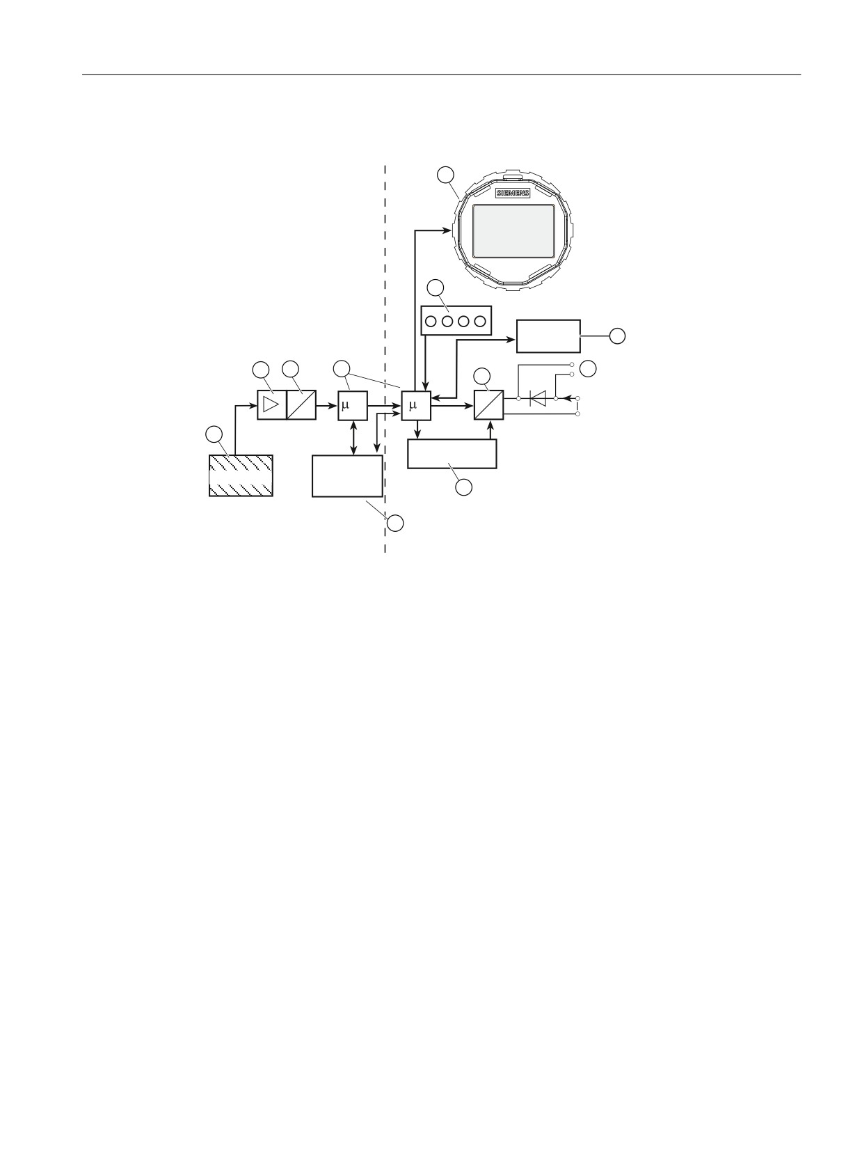
Electronics
((3520
,$
$
'
&
&
8
'
$
+
+$57 PRGHP
6HQVRU
((3520
6HQVRU HOHFWURQLFV
7UDQVPLWWHU HOHFWURQLFV
① Measuring cell sensor
⑧ Buttons
② Measuring amplifier
⑨ Display
③ Analog-to-digital converter
⑩ Connection for external ammeter
④ Microcontroller
⑪ EEPROM
⑤ Digital-to-analog converter
IA
Output current
⑥ EEPROM
UH Auxiliary power
⑦ HART modem
Mode of operation
● The inlet pressure is converted into an electrical signal by the sensor ①.
● This signal is amplified by the measuring amplifier ② and digitized in an analog-to-digital
converter ③.
● The digital signal is analyzed in a microcontroller ④ and corrected with regard to linearity
and thermal characteristics.
● The digital signal is then converted in a digital-to-analog converter ⑤ into the output current
of 4 to 20 mA.
A diode circuit provides reverse polarity protection.
SITRANS P320/P420 with 4 to 20 mA/HART
31
Description
4.4 Functional principle
● You can make an uninterrupted current measurement with a low resistance ammeter at the
connection ⑩.
● The measuring cell-specific data, electronics data and parameter assignment data are
saved in two EEPROM modules. The first EEPROM module ⑥ is linked to the measuring
cell, the second EEPROM module ⑪ to the electronics.
Operation
● The buttons⑧ can be used to call up individual functions.
● If you have a device with a display ⑨, you can view the measurement results, parameter
values and messages.
● With a computer and HART modem ⑦, you can operate the device via the engineering
system (e.g. SIMATIC PDM).
4.4.2
Measuring cell
The following modes of operation are described:
● Gauge pressure
● Absolute pressure
● Differential pressure and flow
● Level
The following process connections are available, for example:
● G1/2 B, 1/2-14 NPT
● Male thread: M20
● Flange connection in accordance with EN 61518
● Flush-mounted process connections
SITRANS P320/P420 with 4 to 20 mA/HART
32

Description
4.4 Functional principle
In the following sections, the process variable to be measured is generally called inlet pressure.
WARNING
Destruction of the seal diaphragm
Danger of injury or damage to device
If the seal membrane is destroyed, the sensor may also be destroyed. If the seal membrane
is destroyed, no reliable measured values can be output.
Hot, toxic and corrosive process media can be released.
● Ensure that the material of the device parts wetted by the process medium is suitable for
the medium. Refer to the information in section Technical data (Page 199).
● Make sure that the device is suitable for the maximum operating pressure of your system.
Refer to the information on the nameplate and/or in Technical data (Page 199).
● Define maintenance intervals for regular inspections in line with device use and empirical
values. The maintenance intervals will vary from site to site depending on corrosion
resistance.
4.4.2.1
Measuring cell for gauge pressure
SH
① Reference pressure opening
⑤ Filling liquid
② Measuring cell
⑥ Gauge pressure sensor
③ Process connection
pe
Inlet pressure
④ Seal diaphragm
Figure 4-7
Function chart of measuring cell for gauge pressure
The inlet pressure (pe) is transferred to the gauge pressure sensor ⑥ via the seal diaphragm
④ and the fill fluid ⑤, displacing its measuring diaphragm. The displacement changes the
resistance of the four piezoresistors (bridge circuit) of the gauge pressure sensor. The change
in the resistance causes a bridge output voltage proportional to the inlet pressure.
Pressure transmitters with measuring span ≤ 63 bar measure the inlet pressure against
atmosphere, those with measuring spans ≥ 160 bar the inlet pressure against vacuum.
SITRANS P320/P420 with 4 to 20 mA/HART
33

Description
4.4 Functional principle
4.4.2.2
Measuring cell for gauge pressure, front-flush membrane
SH
① Reference pressure opening
⑤ Filling liquid
② Measuring cell
⑥ Gauge pressure sensor
③ Process connection
pe
Inlet pressure
④ Seal diaphragm
Figure 4-8
Function chart of the measuring cell for gauge pressure, flush mounted diaphragm
The inlet pressure (pe) is transferred to the gauge pressure sensor ⑥ via the seal diaphragm
④ and the filling liquid ⑤, displacing its measuring diaphragm. The displacement changes the
resistance of the four piezoresistors (bridge circuit) of the gauge pressure sensor. The change
in the resistance causes a bridge output voltage proportional to the inlet pressure.
Pressure transmitters with measuring span ≤ 63 bar measure the inlet pressure against
atmosphere, those with measuring spans ≥ 160 bar the inlet pressure against vacuum.
4.4.2.3
Measuring cell for absolute pressure from the gauge pressure series
SH
① Measuring cell
④ Filling liquid
② Process connection
⑤ Absolute pressure sensor
③ Seal diaphragm
Pe
Inlet pressure
Figure 4-9
Function chart of measuring cell for absolute pressure
SITRANS P320/P420 with 4 to 20 mA/HART
34

Description
4.4 Functional principle
● The inlet pressure (pe) is transferred to the absolute pressure sensor ⑤ via the seal
diaphragm ③ and the fill fluid ④, displacing its measuring diaphragm.
● The displacement changes the resistance of the four piezoresistors (bridge circuit) of the
absolute pressure sensor.
● The change in the resistance causes a bridge output voltage proportional to the inlet
pressure.
4.4.2.4
Measuring cell for absolute pressure, front-flush membrane
SH
① Measuring cell
④ Filling liquid
② Process connection
⑤ Absolute pressure sensor
③ Seal diaphragm
pe
Inlet pressure
Figure 4-10
Function chart of the measuring cell for absolute pressure, flush mounted diaphragm
● The inlet pressure (pe) is transferred to the absolute pressure sensor ⑤ via the seal
diaphragm ③ and the filling liquid ④, and displaces its measuring diaphragm.
● The displacement changes the resistance of the four piezoresistors (bridge circuit) of the
absolute pressure sensor.
● The change in the resistance causes a bridge output voltage proportional to the inlet
pressure.
SITRANS P320/P420 with 4 to 20 mA/HART
35

Description
4.4 Functional principle
4.4.2.5
Measuring cell for absolute pressure from the differential pressure series
SH
① Pressure cap
⑥ Overload diaphragm
② Seal diaphragm on the measuring cell
⑦ Measuring cell filling liquid
③ O-ring
⑧ Reference pressure
④ Measuring cell body
pe
Pressure input variable
⑤ Absolute pressure sensor
Figure 4-11
Function chart of measuring cell for absolute pressure
● Absolute pressure is transmitted to the absolute pressure sensor ⑤ through the seal
diaphragm ② and the filling liquid ⑦.
● When measuring limits are exceeded, the overload diaphragm ⑥ is displaced until the seal
diaphragm ② rests on the measuring cell body ④. The seal diaphragm thus protects the
absolute pressure sensor ⑤ from overload.
● The difference between the inlet pressure (pe) and the reference pressure ⑧ on the
negative side of the measuring cell displaces the seal diaphragm ②. The displacement
changes the resistance of the four piezoresistors (bridge circuit) of the absolute pressure
sensor.
● The change in the resistance causes a bridge output voltage proportional to the absolute
pressure.
SITRANS P320/P420 with 4 to 20 mA/HART
36

Description
4.4 Functional principle
4.4.2.6
Measuring cell for differential pressure and flow rate
① Inlet pressure P+
⑥ Filling liquid
② Pressure cap
⑦ Seal diaphragm
③ O-ring
⑧ Inlet pressure P-
④ Measuring cell body
⑨ Differential pressure sensor
⑤ Overload diaphragm
Figure 4-12
Function chart of the measuring cell for differential pressure and flow rate
● Differential pressure is transmitted to the differential pressure sensor ⑨ through the seal
diaphragms ⑦ and the filling liquid ⑥.
● When measuring limits are exceeded, the seal diaphragm ⑦ is displaced until the seal
diaphragm rests on the measuring cell body ④. The differential pressure sensor ⑨ is thus
protected against overloading since no further deflection of the overload diaphragm ⑤ is
possible.
● The seal diaphragm ⑦ is displaced by the differential pressure. The displacement changes
the resistance of the four piezoresistors (bridge circuit) of the differential pressure sensor.
● The change in the resistance causes a bridge output voltage proportional to the differential
pressure.
SITRANS P320/P420 with 4 to 20 mA/HART
37

Description
4.5 System configuration
4.4.2.7
Measuring cell for level
① Inlet pressure P+
⑦ Overload diaphragm
② Seal diaphragm on the measuring cell
⑧ Inlet pressure P-
③ Pressure cap
⑨ Filling liquid of the measuring cell
④ O-ring
⑩ Capillary tube with the fill fluid of the mounting
flange
⑤ Differential pressure sensor
⑪ Flange with a tube
⑥ Measuring cell body
⑫ Seal diaphragm on the mounting flange
Figure 4-13
Function chart of the measuring cell for level
● The inlet pressure (hydrostatic pressure) ① works hydraulically on the measuring cell
through the seal diaphragm on the mounting flange ⑫.
● The differential pressure at the measuring cell is transmitted to the differential pressure
sensor ⑤ through the seal diaphragms ② and the filling liquid ⑨.
● When measuring limits are exceeded, the overload diaphragm ⑦ is displaced until one of
the seal diaphragms ② or ⑫ rests on the measuring cell body ⑥. The seal diaphragms ②
thus protect the differential pressure sensor ⑤ from overload.
● The seal diaphragm ② is displaced by the differential pressure. The displacement changes
the resistance of the four doped piezoresistors in the bridge circuit.
● The change in the resistance causes a bridge output voltage proportional to the differential
pressure.
4.5
System configuration
Introduction
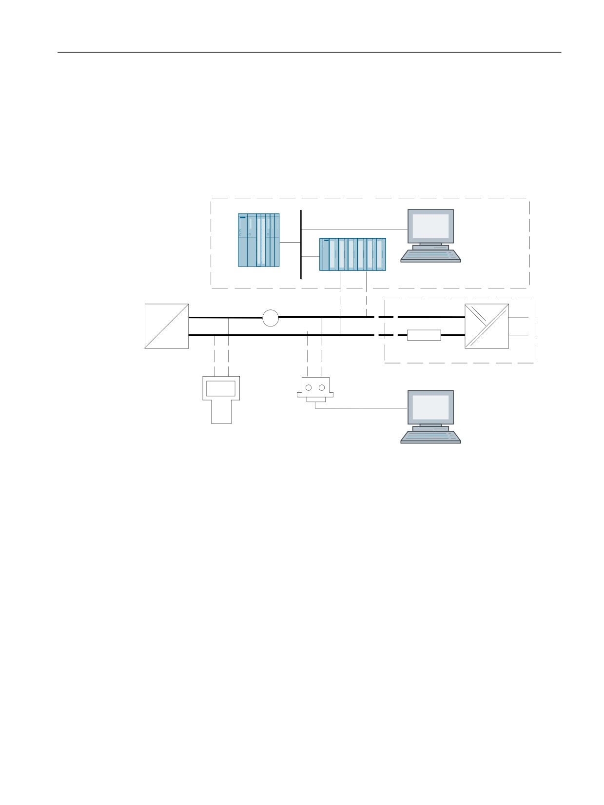
The pressure transmitter can be used in a number of system configurations:
● As a stand-alone version, supplied with the necessary auxiliary power
● As part of a complex system environment, e.g. SIMATIC S7
SITRANS P320/P420 with 4 to 20 mA/HART
38
Description
4.5 System configuration
System communication
Communication is via the HART protocol, using:
● HART Communicator (load 230 ... 1100 Ω)
● PC with HART modem on which appropriate software is installed, e.g. SIMATIC PDM (load
230 ... 600 Ω)
● Control system which can communicate via the HART protocol, e.g. SIMATIC PCS7
&RQWURO V\VWHP
6,0$7,& 3'0
6
(7
0
RU
$
/RDG
7UDQVPLWWHU
$X[LOLDU\ SRZHU
+$57
RU
+$57
&RPPXQLFDWRU
0RGHP
3& ODSWRS ZLWK
6,0$7,& 3'0
Figure 4-14
Possible system configuration
Devices with "intrinsically safe" type of protection
For an intrinsically safe supply, use only intrinsically safe HART communicators (e.g. FC475)
or intrinsically safe HART modems.
SITRANS P320/P420 with 4 to 20 mA/HART
39
//////////////////////////////////////////