Siemens simatic S7-1200. Manual (2015) - page 7
Technical specifications
A.1 General technical specifications
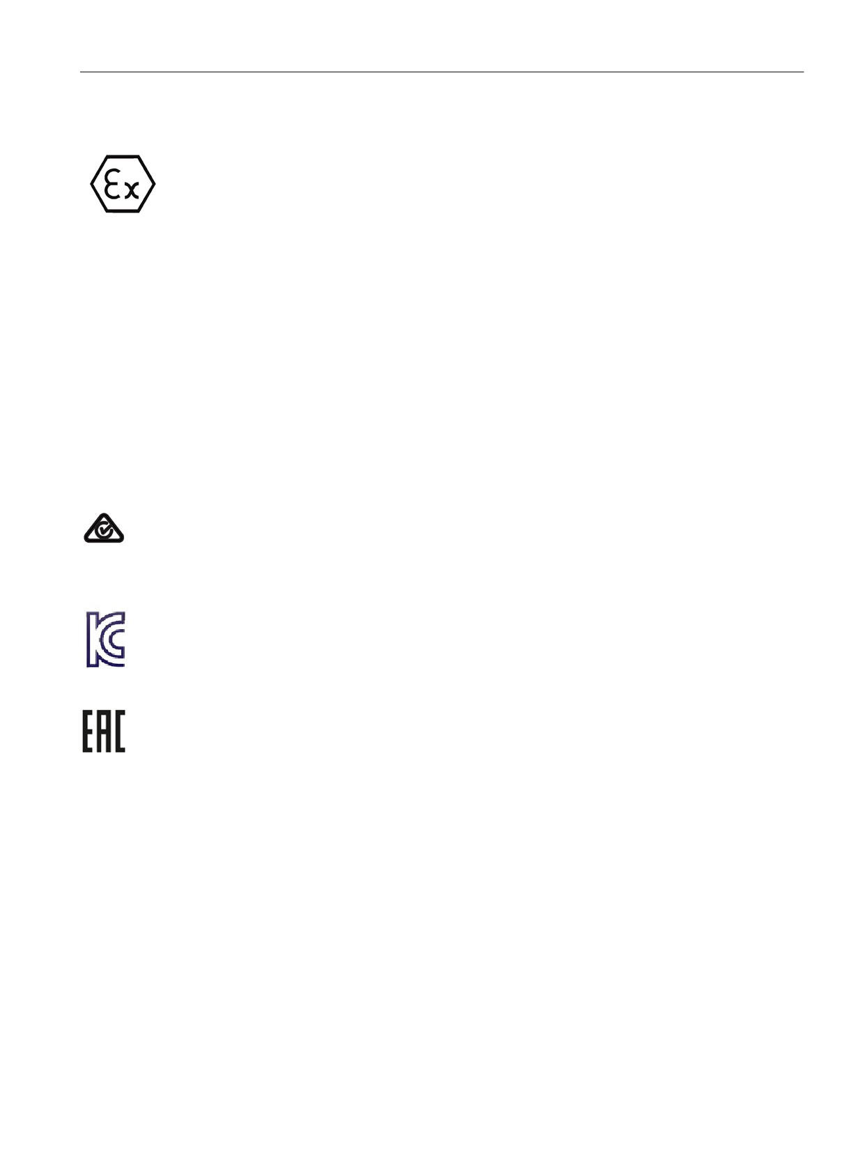
ATEX approval
ATEX approval applies to DC models only. ATEX approval does not apply to AC and Relay
models.
EN 60079-0:2009: Explosive Atmospheres - General Requirements
EN 60079-15:2010: Electrical Apparatus for Potentially Explosive Atmospheres;
Type of protection 'nA'
II 3 G Ex nA IIC T4 or T3 Gc
Install modules in a suitable enclosure providing a minimum degree of protection of IP54
according to EN 60529, or in a location providing an equivalent degree of protection.
Attached cables and conductors should be rated for the actual temperature measured under
rated conditions.
The installation should ensure that transients are limited to less than 119 V. See Surge
immunity in this section.
IMPORTANT EXCEPTION: See Technical Specifications for the number of inputs or outputs
allowed on simultaneously. Some models are de-rated for Ta = 60 °C.
C-Tick approval
The S7-1200 automation system satisfies requirements of standards to AS/NZS CISPR16
(Class A).
Korea Certification
The S7-1200 automation system satisfies the requirements of the Korean Certification (KC
Mark). It has been defined as Class A Equipment and is intended for industrial applications
and has not been considered for home use.
Eurasian Customs Union approval (Belarus, Kazakhstan, Russian Federation)
EAC (Eurasion Conformity): Declaration of Conformity according to Technical Regulation of
Customs Union (TR CU)
363
Technical specifications
A.1 General technical specifications
Maritime approval
The S7-1200 products are periodically submitted for special agency approvals related to
specific markets and applications. Consult your local Siemens representative if you need
additional information related to the latest listing of exact approvals by part number.
Classification societies:
● ABS (American Bureau of Shipping)
● BV (Bureau Veritas)
● DNV (Det Norske Veritas)
● GL (Germanischer Lloyd)
● LRS (Lloyds Register of Shipping)
● Class NK (Nippon Kaiji Kyokai)
● Korean Register of Shipping
Industrial environments
The S7-1200 automation system is designed for use in industrial environments.
Table A- 1 Industrial environments
Application field
Emission requirements
Immunity requirements
Noise immunity re-
quirements
Industrial
EN 61000-6-4:2007+A1:2011
EN 61000-6-2:2005
EN 61000-6-2:2005
Note
The S7-1200 automation system is intended for use in industrial areas; use in residential
areas can have an impact on radio or TV reception. If you use the S7-1200 in residential
areas, you must ensure that its radio interference emission complies with the limit value
Class B in accordance with EN 55011.
Examples of suitable measures for achieving RF interference, level Class B include:
- Installation of the S7-1200 in a grounded control cabinet
- Use of noise filters in the supply lines
Ensure that the radio interference emission complies with Class B in accordance with EN
55011.
Individual acceptance is required (final installation must meet all safety and EMC
requirements of a residential installation).
364
Technical specifications
A.1 General technical specifications
Electromagnetic compatibility
Electromagnetic Compatibility (EMC) is the ability of an electrical device to operate as
intended in an electromagnetic environment and to operate without emitting levels of
electromagnetic interference (EMI) that may disturb other electrical devices in the vicinity.
Table A- 2 Immunity per EN 61000-6-2
Electromagnetic compatibility - Immunity per EN 61000-6-2
EN 61000-4-2
8 kV air discharge to all surfaces
Electrostatic discharge
6 kV contact discharge to exposed conductive surfaces
EN 61000-4-3
80 to 1000 MHz, 10 V/m, 80% AM at 1 kHz
Radiated, radio-frequency, elec-
1.4 to 2.0 GHz, 3 V/m, 80% AM at 1 kHz
tromagnetic field immunity test
2.0 to 2.7 GHz, 1 V/m, 80% AM at 1 kHz
EN 61000-4-4
2 kV, 5 kHz with coupling network to AC and DC system power
Fast transient bursts
2 kV, 5 kHz with coupling clamp to I/O
EN 6100-4-5
AC systems - 2 kV common mode, 1 kV differential mode
Surge immunity
DC systems - 2 kV common mode, 1 kV differential mode
For DC systems, refer to Surge immunity below
EN 61000-4-6
150 kHz to 80 MHz, 10 V RMS, 80% AM at 1kHz
Conducted disturbances
EN 61000-4-11
AC systems
Voltage dips
0% for 1 cycle, 40% for 12 cycles and 70% for 30 cycles at 60
Hz
Surge immunity
Wiring systems subject to surges from lightning strike coupling must be equipped with
external protection. One specification for evaluation of protection from lightning type surges
is found in EN 61000-4-5, with operational limits established by EN 61000-6-2. S7-1200 DC
CPUs and signal modules require external protection to maintain safe operation when
subject to surge voltages defined by this standard.
Listed below are some devices that support the needed surge immunity protection. These
devices only provide the protection if they are properly installed according to the
manufacturer's recommendations. Devices manufactured by other vendors with the same or
better specifications can also be used:
Table A- 3 Devices that support surge immunity protection
Sub-system
Protection device
+24 VDC power
BLITZDUCTOR VT, BVT AVD 24, Part Number 918 422
Industrial Ethernet
DEHNpatch DPA M CLE RJ45B 48, Part Number 929 121
RS-485
BLITZDUCTOR XT, Basic Unit BXT BAS, Part Number 920 300
BLITZDUCTOR XT, Module BXT ML2 BD HFS 5, Part Number 920 271
RS-232
BLITZDUCTOR XT, Basic Unit BXT BAS, Part Number 920 300
BLITZDUCTOR XT, Module BXT ML2 BE S 12, Part Number 920 222
+24 VDC digital inputs
DEHN, Inc., Type DCO SD2 E 24, Part Number 917 988
+24 VDC digital outputs
DEHN, Inc., Type DCO SD2 E 24, Part Number 917 988
and sensor supply
365
Technical specifications
A.1 General technical specifications
Sub-system
Protection device
Analog IO
DEHN, Inc., Type DCO SD2 E 12, Part Number 917 987
Relay outputs
None required
Table A- 4 Conducted and radiated emissions per EN 61000-6-4
Electromagnetic compatibility - Conducted and radiated emissions per EN 61000-6-4
Conducted Emissions
0.15 MHz to 0.5 MHz
<79dB (μV) quasi-peak; <66 dB (μV) average
EN 55011, Class A, Group 1
0.5 MHz to 5 MHz
<73dB (μV) quasi-peak; <60 dB (μV) average
5 MHz to 30 MHz
<73dB (μV) quasi-peak; <60 dB (μV) average
Radiated Emissions
30 MHz to 230 MHz
<40dB (μV/m) quasi-peak; measured at 10m
EN 55011, Class A, Group 1
230 MHz to 1 GHz
<47dB (μV/m) quasi-peak; measured at 10m
1 GHz to 3 GHz
< 76dB (uV/m) quasi peak, measured at 10m
Environmental conditions
Table A- 5 Transport and storage
Environmental conditions - Transport and storage
EN 60068-2-2, Test Bb, Dry heat and
-40 °C to +70 °C
EN 60068-2-1, Test Ab, Cold
EN 60068-2-30, Test Db, Damp heat
25 °C to 55 °C, 95% humidity
EN 60068-2-14, Test Na, temperature
-40 °C to +70 °C, dwell time 3 hours, 5 cycles
shock
EN 60068-2-32, Free fall
0.3 m, 5 times, product packaging
Atmospheric pressure
1080 to 660h Pa (corresponding to an altitude of -1000
to 3500m)
Table A- 6 Operating conditions
Environmental conditions - Operating
Ambient temperature range
-20 °C to 60 °C horizontal mounting
(Inlet Air 25 mm below unit)
-20 °C to 50 °C vertical mounting
95% non-condensing humidity
Unless otherwise specified
Atmospheric pressure
1080 to 795 hPa (corresponding to an altitude of -1000
to 2000m)
Concentration of contaminants
S02: < 0.5 ppm; H2S: < 0.1 ppm; RH < 60% non-
condensing
ISA-S71.04 severity level G1, G2, G3
EN 60068-2-14, Test Nb, temperature
5 °C to 55 °C, 3 °C/minute
change
366
Technical specifications
A.1 General technical specifications
Environmental conditions - Operating
EN 60068-2-27 Mechanical shock
15 G, 11 ms pulse, 6 shocks in each of 3 axis
EN 60068-2-6 Sinusoidal vibration
DIN rail mount: 3.5 mm from 5-9 Hz, 1G from 9 - 150 Hz
Panel Mount: 7.0 mm from 5-9 Hz, 2G from 9 to 150 Hz
10 sweeps each axis, 1 octave per minute
Table A- 7 High potential isolation test
High potential isolation test
24 VDC / 5 VDC nominal circuits
520 VDC (type test of optical isolation boundaries)
115 VAC / 230 VAC circuits to ground
1500 VAC
115 VAC / 230 VAC circuits to 115 VAC /
1500 VAC
230 VAC circuits
115 VAC / 230 VAC circuits to 24 VDC /
1500 VAC (3000 VAC/4242 VDC type test)
5 VDC circuits
Ethernet port to 24 VDC / 5 VDC circuits
1500 VAC (type test only)
and ground1
1
Ethernet port isolation is designed to limit hazard during short term network faults to hazardous
voltages. It does not conform to safety requirements for routine AC line voltage isolation.
Protection class
● Protection Class II according to EN 61131-2 (Protective conductor not required)
Degree of protection
● IP20 Mechanical Protection, EN 60529
● Protects against finger contact with high voltage as tested by standard probe. External
protection required for dust, dirt, water and foreign objects of < 12.5mm in diameter.
Rated voltages
Table A- 8 Rated voltages
Rated voltage
Tolerance
24 VDC
20.4 VDC to 28.8 VDC
120/230 VAC
85 VAC to 264 VAC, 47 to 63 Hz
367
Technical specifications
A.1 General technical specifications
Reverse voltage protection
Reverse voltage protection circuitry is provided on each terminal pair of +24 VDC power or
user input power for CPUs, signal modules (SMs), and signal boards (SBs). It is still possible
to damage the system by wiring different terminal pairs in opposite polarities.
Some of the 24 VDC power input ports in the S7-1200 system are interconnected, with a
common logic circuit connecting multiple M terminals. For example, the following circuits are
interconnected when designated as "not isolated" in the data sheets: the 24 VDC power
supply of the CPU, the sensor power of the CPU, the power input for the relay coil of an SM,
and the power supply for a non-isolated analog input. All non-isolated M terminals must
connect to the same external reference potential.
WARNING
Connecting non-isolated M terminals to different reference potentials will cause unintended
current flows that may cause damage or unpredictable operation in the PLC and any
connected equipment.
Failure to comply with these guidelines could cause damage or unpredictable operation
which could result in death or severe personal injury and/or property damage.
Always ensure that all non-isolated M terminals in an S7-1200 system are connected to the
same reference potential.
DC Outputs
Short -circuit protection circuitry is not provided for DC outputs on CPUs, signal modules
(SMs) and signal boards (SBs).
368
Technical specifications
A.1 General technical specifications
Relay electrical service life
The typical performance data estimated from sample tests is shown below. Actual
performance may vary depending upon your specific application. An external protection
circuit that is adapted to the load will enhance the service life of the contacts. N.C. contacts
have a typical service life of about one-third that of the N.O. contact under inductive and
lamp load conditions.
An external protective circuit will increase the service life of the contacts.
Table A- 9 Typical performance data
Data for selecting an actuator
Continuous thermal current
2 A max.
Switching capacity and life of the contacts
For ohmic load
Voltage
Current
Number of operating cycles
(typical)
24 VDC
2.0 A
0.1 million
24 VDC
1.0 A
0.2 million
24 VDC
0.5 A
1.0 million
48 VAC
1.5 A
1.5 million
60 VAC
1.5 A
1.5 million
120 VAC
2.0 A
1.0 million
120 VAC
1.0 A
1.5 million
120 VAC
0.5 A
2.0 million
230 VAC
2.0 A
1.0 million
230 VAC
1.0 A
1.5 million
230 VAC
0.5 A
2.0 million
For inductive load (according to
Voltage
Current
Number of operating cycles
(typical)
IEC 947-5-1 DC13/AC15)
24 VDC
2.0 A
0.05 million
24 VDC
1.0 A
0.1 million
24 VDC
0.5 A
0.5 million
24 VAC
1.5 A
1.0 million
48 VAC
1.5 A
1.0 million
60 VAC
1.5 A
1.0 million
120 VAC
2.0 A
0.7 million
120 VAC
1.0 A
1.0 million
120 VAC
0.5 A
1.5 million
230 VAC
2.0 A
0.7 million
230 VAC
1.0 A
1.0 million
230 VAC
0.5 A
1.5 million
Activating a digital input
Possible
Switching frequency
Mechanical
Max. 10 Hz
At ohmic load
Max. 1 Hz
369

Technical specifications
A.1 General technical specifications
Data for selecting an actuator
At inductive load (according to IEC
Max. 0.5 Hz
947-5-1 DC13/AC15)
At lamp load
Max. 1Hz
Internal CPU memory retention
● Lifetime of retentive data and data log data: 10 years
● Power down retentive data, Write cycle endurance: 2 million cycles
● Data log data, up to 2 KB per data log entry, Write cycle endurance: 500 million data log
entries
Note
Effect of data logs on internal CPU memory
Each data log write consumes at a minimum 2 KB of memory. If your program writes small
amounts of data frequently, it is consuming at least 2 KB of memory on each write. A better
implementation would be to accumulate the small data items in a data block (DB), and to
write the data block to the data log at less frequent intervals.
If your program writes many data log entries at a high frequency, consider using a
replaceable SD memory card.
370
Technical specifications
A.2 CPU modules
A.2
CPU modules
For a more complete list of modules available for S7-1200, refer to the S7-1200
Programmable Controller System Manual or to the customer support web site
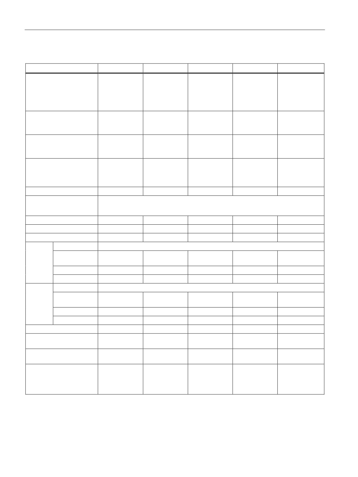
Table A- 10 General specifications
General specifications
CPU 1211C
CPU 1212C
CPU 1214C
CPU 1215C
CPU 1217C
Article
AC/DC/Relay
6ES7 211-
6ES7 212-
6ES7 214-
6ES7 215-
--
number
1BE40-0XB0
1BE40-0XB0
1BG40-0XB0
1BG40-0XB0
DC/DC/Relay
6ES7 211-
6ES7 212-
6ES7 214-
6ES7 215-
--
1HE40-0XB0
1HE40-0XB0
1HG40-0XB0
1HG40-0XB0
DC/DC/DC
6ES7 211-
6ES7 212-
6ES7 214-
6ES7 215-
6ES7 217-
1AE40-0XB0
1AE40-0XB0
1AG40-0XB0
1AG40-0XB0
1AG40-0XB0
Dimensions W x H x D
90 x 100 x 75
110 x 100 x 75
130 x 100 x 75
150 x 100 x 75
(mm)
Weight
• AC/DC/Rel
•
420 grams
•
425 grams
•
475 grams
•
585 grams
-
ay
-
•
380 grams
•
385 grams
•
435 grams
•
550 grams
• DC/DC/Rel
530 grams
•
370 grams
•
370 grams
•
415 grams
•
520 grams
ay
• DC/DC/DC
Power
• AC/DC/Rel
•
10 W
•
11 W
•
14 W
•
14 W
-
dissipa-
ay
-
•
8 W
•
9 W
•
12 W
•
12 W
tion
• DC/DC/Rel
12 W
•
8 W
•
9 W
•
12 W
•
12 W
ay
• DC/DC/DC
Current available (5 VDC)
750 mA max.
1000 mA max.
1600 mA max.
1600 mA max.
1600 mA max.
for SM and CM bus
Current available
300 mA max.
300 mA max.
400 mA max.
400 mA max.
400 mA max.
(24 VDC) sensor power
Digital input current con-
4 mA/input used
4 mA/input used
4 mA/input used
4 mA/inputs used
4 mA/input used
sumption (24 VDC)
371
Technical specifications
A.2 CPU modules
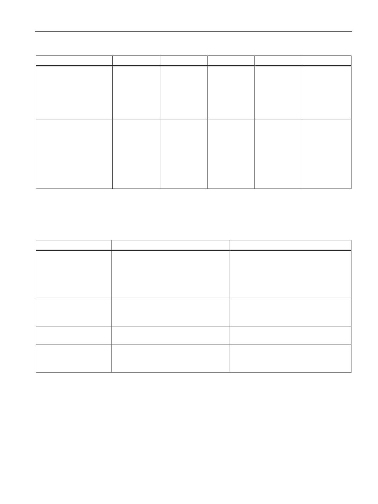
Table A- 11 CPU features
CPU features
CPU 1211C
CPU 1212C
CPU 1214C
CPU 1215C
CPU 1217C
User memory
• Work memory
•
50 Kbytes
•
75 Kbytes
•
100 Kbytes
•
125 Kbytes
•
150 Kbytes
• Load memory
•
1 Mbyte
•
1 Mbyte
•
4 Mbytes
•
4 Mbytes
•
4 Mbytes
• Retentive memory
•
10 Kbytes
•
10 Kbytes
•
10 Kbytes
•
10 Kbytes
•
10 Kbytes
On-board digital I/O
6 inputs
8 inputs
14 inputs
14 inputs
14 inputs
See specifications
4 outputs
6 outputs
10 outputs
10 outputs
10 outputs
(Page 384).
On-board analog I/O
2 inputs
2 inputs
2 inputs
2 inputs
2 inputs
See specifications
2 outputs
2 outputs
(Page 395).
Process image size
• Inputs
•
1024 bytes
•
1024 bytes
•
1024 bytes
•
1024 bytes
•
1024 bytes
• Outputs
•
1024 bytes
•
1024 bytes
•
1024 bytes
•
1024 bytes
•
1024 bytes
Bit memory (M)
4096 bytes
4096 bytes
8192 bytes
8192 bytes
8192 bytes
Temporary (local) memory
•
16 Kbytes for startup and program cycle (including associated FBs and FCs)
•
6 Kbytes for each of the other interrupt priority levels (including FBs and FCs)
SM expansion
None
2 SMs max.
8 SMs max.
8 SMs max.
8 SMs max.
SB, CB, or BB expansion
1 max.
1 max.
1 max.
1 max.
1 max.
CM expansion
3 max.
3 max.
3 max.
3 max.
3 max
High-
Total
Up to 6 configured to use any built-in or SB inputs
speed
1 MHz
--
--
--
--
Ib.2 to Ib.5 (Dif-
counters
ferential)
100/180 kHz
Ia.0 to Ia.5
Ia.0 to Ia.5
Ia.0 to Ia.5
Ia.0 to Ia.5
Ia.0 to Ia.5
30/120 kHz
--
Ia.6 to Ia.7
Ia.6 to Ib.5
Ia.6 to Ib.5
Ia.6 to Ib.1
Pulse
Total
Up to 4 configured to use any built-in or SB outputs
outputs2
1 MHz
--
--
--
--
Qa.0 to Qa.3
(Differential)
100 kHz
Qa.0 to Qa.3
Qa.0 to Qa.3
Qa.0to Qa.3
Qa.0 to Qa.3
Qa.4 to Qb.1
30 kHz
--
Qa.4 to Qa.5
Qa.4 to Qb.1
Qa.4 to Qb.1
--
Pulse catch inputs
6
8
14
14
14
Time delay interrupts
4 total with 1 ms
4 total with 1 ms
4 total with 1 ms
4 total with 1 ms
4 total with 1 ms
resolution
resolution
resolution
resolution
resolution
Cyclic interrupts
4 total with 1 ms
4 total with 1 ms
4 total with 1 ms
4 total with 1 ms
4 total with 1 ms
resolution
resolution
resolution
resolution
resolution
Edge interrupts
6 rising and 6
8 rising and 8
12 rising and 12
12 rising and 12
12 rising and 12
falling
falling
falling
falling
falling
10 rising and 10
12 rising and 12
16 rising and 16
16 rising and 16
16 rising and 16
With optional SB
falling
falling
falling
falling
falling
372
Technical specifications
A.2 CPU modules
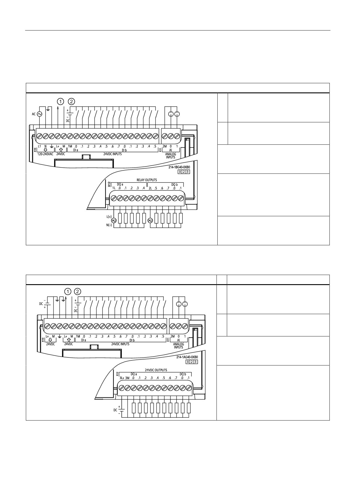
CPU features
CPU 1211C
CPU 1212C
CPU 1214C
CPU 1215C
CPU 1217C
Real time clock
• Accuracy
•
+/- 60 sec-
•
+/- 60 sec-
•
+/- 60 sec-
•
+/- 60 sec-
•
+/- 60 sec-
onds/ month
onds/ month
onds/ month
onds/ month
onds/ month
• Retention time (mainte-
•
20 days
•
20 days
•
20 days
•
20 days
•
20 days
nance-free Super Ca-
typ./12 days
typ./12 days
typ./12 days
typ./12 days
typ./12 days
pacitor)
min. at 40 °C
min. at 40 °C
min. at 40 °C
min. at 40 °C
min. at 40 °C
Execution speed
• Boolean
•
0.08 μs/
•
0.08 μs/
•
0.08 μs /
•
0.08 μs/
•
0.08 μs/ in-
instruction
instruction
instruction
instruction
struction
• Move Word
•
1.7μs/ in-
•
1.7 μs/ in-
•
1.7μs/ in-
•
1.7μs/ in-
•
1.7 μs/ in-
struction
struction
struction
struction
struction
•
2.3 μs/ in-
•
2.3 μs/ in-
•
2.3 μs/ in-
•
2.3 μs/ in-
•
2.3 μs/ in-
• Real Math
struction
struction
struction
struction
struction
1
The slower speed is applicable when the HSC is configured for quadrature mode of operation.
2
For CPU models with relay outputs, you must install a digital signal board (SB) to use the pulse outputs.
Table A- 12 Communication
Technical data
CPU 1211C, CPU 1212C, CPU 1214C
CPU 1215C, CPU 1217C
Communication
1 Ethernet port
2 Ethernet ports
• Data rates
•
10/100 Mb/s
•
10/100 Mb/s
• Isolation (external signal
•
Transformer isolated, 1500 VDC
•
Transformer isolated, 1500 VDC
to PLC logic)
•
CAT5e shielded
•
CAT5e shielded
• Cable type
Devices
•
4 HMI
•
4 HMI
•
1 PG
•
1 PG
Ethernet connections1
8 (active or passive)
8 (active or passive)
CPU-to-CPU
•
8 (client)
•
8 (client)
S7 connections (GET/PUT)
•
3 (server)
•
3 (server)
1
Open User Communication connections (active or passive): TSEND_C, TRCV_C, TCON, TDISCON, TSEND, and
TRCV.
373
Technical specifications
A.2 CPU modules
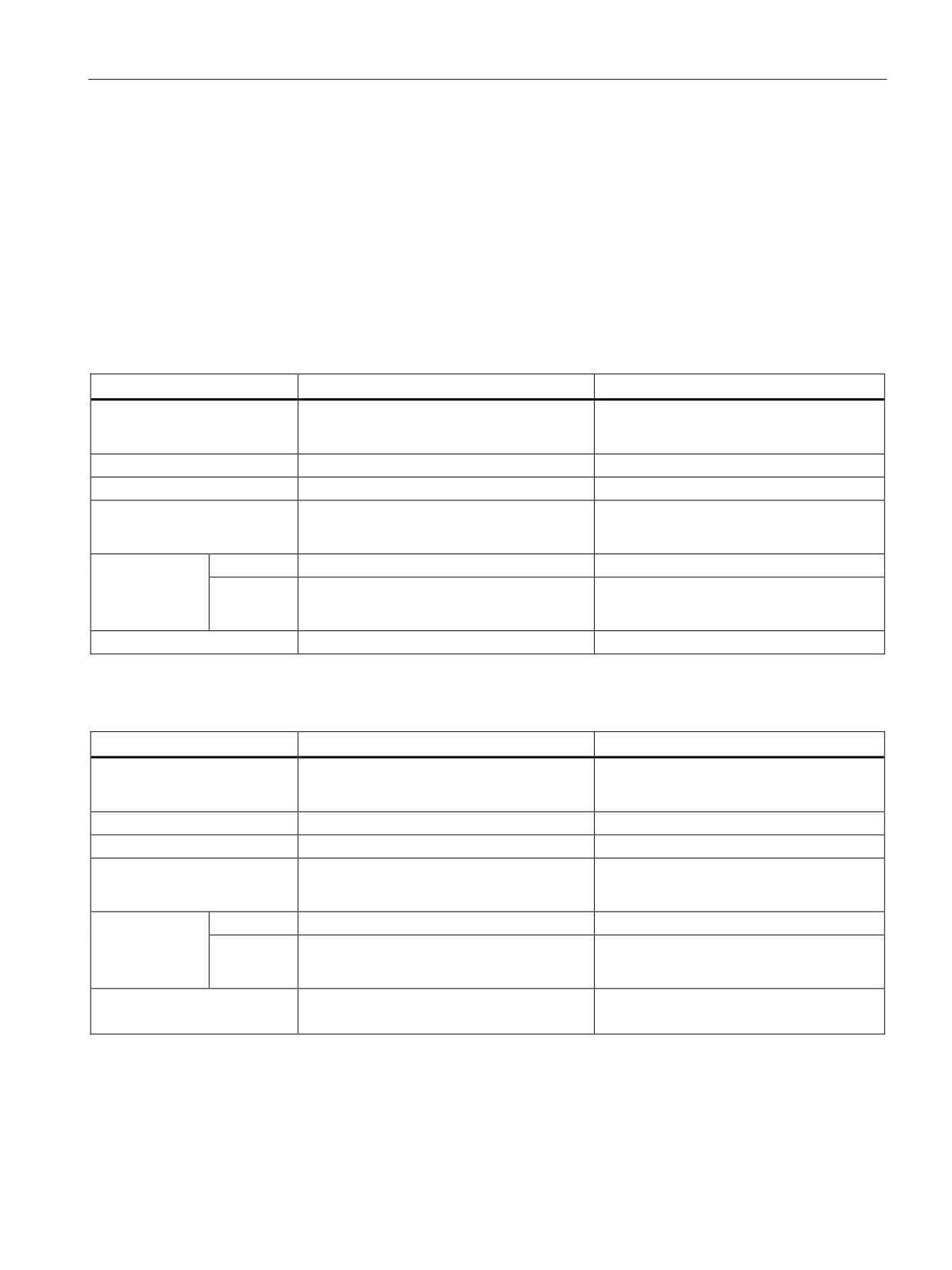
Table A- 13 Wiring diagram for CPU 1214C AC/DC/Relay
CPU 1214C AC/DC/Relay
24 VDC Sensor Power Out. For addi-
①
tional noise immunity, connect "M" to
chassis ground even if not using sensor
supply.
For sinking inputs, connect "-" to "M"
②
(shown). For sourcing inputs, connect
"+" to "M".
Note 1: X11 connectors must be gold. See
the S7-1200 Programmable Controller Sys-
tem Manual, Appendix C, Spare Parts for
article number.
Note 2: Either the L1 or N (L2) terminal can
be connected to a voltage source up to
240 VAC. The N terminal can be consid-
ered L2 and is not required to be grounded.
No polarization is required for L1 and N (L2)
terminals.
Note 3: See the S7-1200 Programmable
Controller System Manual, Device configu-
ration, for information about the Ethernet
port of the CPU.
Table A- 14 Wiring diagram for CPU 1214C DC/DC/DC
CPU 1214C DC/DC/DC
24 VDC Sensor Power Out. For addi-
①
tional noise immunity, connect "M" to
chassis ground even if not using sensor
supply.
For sinking inputs, connect "-" to "M"
②
(shown). For sourcing inputs, connect
"+" to "M".
Note 1: X11 connectors must be gold. See
the S7-1200 Programmable Controller Sys-
tem Manual, Appendix C, Spare Parts for
article number.
Note 2: See the S7-1200 Programmable
Controller System Manual, Device configu-
ration, for information about the Ethernet
port of the CPU.
374
Technical specifications
A.3 Digital I/O modules
A.3
Digital I/O modules
For a more complete list of modules available for S7-1200, refer to the S7-1200
Programmable Controller System Manual or to the customer support web site
A.3.1
SB 1221, SB 1222, and SB 1223 digital input/output (DI, DQ, and DI/DQ)
Table A- 15 SB 1221 digital input (DI) and SB 1222 digital output (DQ) modules
General
SB 1221 4 DI (200 kHz)
SB 1222 4 DQ (200 kHz)
Article number
•
24 VDC: 6ES7 221-3BD30-0XB0
•
24 VDC: 6ES7 222-1BD30-0XB0
•
5 VDC: 6ES7 221-3AD30-0XB0
•
5 VDC: 6ES7 222-1AD30-0XB0
Dimensions W x H x D (mm)
38 x 62 x 21
38 x 62 x 21
Weight
35 grams
35 grams
Power dissipation
•
24 VDC: 1.5 W
0.5 W
•
5 VDC: 1.0 W
Current con-
SM Bus
40 mA
35 mA
sumption
24 VDC
•
24 VDC: 7 mA / input + 20 mA
15 mA
•
5 VDC: 15 mA / input + 15 mA
Inputs/outputs
4 inputs (source)
4 outputs (solid state - MOSFET)
Table A- 16 SB 1223 combination digital input/output (DI / DQ) modules
General
SB 1223 DI / DQ (200 kHz)
SB 1223 2 DI / 2 DQ
Article number
•
24 VDC: 6ES7 223-3BD30-0XB0
24 VDC: 6ES7 223-0BD30-0XB0
•
5 VDC: 6ES7 223-3AD30-0XB0
Dimensions W x H x D (mm)
38 x 62 x 21
38 x 62 x 21
Weight
35 grams
40 grams
Power dissipation
•
24 VDC: 1.0 W
24 VDC: 1.0 W
•
5 VDC: 0.5 W
Current con-
SM Bus
35 mA
50 mA
sumption
24 VDC
•
24 VDC: 7 mA / input + 20 mA
4 mA / input used
•
5 VDC: 15 mA / input + 15 mA
Inputs/outputs
2 inputs (source)
2 inputs (IEC Type 1 sink)
2 outputs (solid state - MOSFET)
2 outputs (solid state - MOSFET)
375
Technical specifications
A.3 Digital I/O modules
Note
The high-speed (200 kHz) SBs utilize "sourcing" inputs. The standard SB (20 kHz) utilizes
"sinking" inputs. Refer to the specifications for the digital inputs and outputs (Page 384).
The high-speed (200 kHz) outputs (SB 1222 and SB 1223) can be either sourcing or sinking.
For sourcing outputs, connect "Load" to "-" (shown). For sinking outputs, connect "Load" to
"+". Because both sinking and sourcing configurations are supported by the same circuitry,
the active state of a sourcing load is opposite that of a sinking load. A source output exhibits
positive logic (Q bit and LED are ON when the load has current flow), while a sink output
exhibits negative logic (Q bit and LED are OFF when the load has current flow). If the
module is plugged in with no user program, the default for this module is 0V, which means
that a sinking load will be turned ON.
376
Technical specifications
A.3 Digital I/O modules
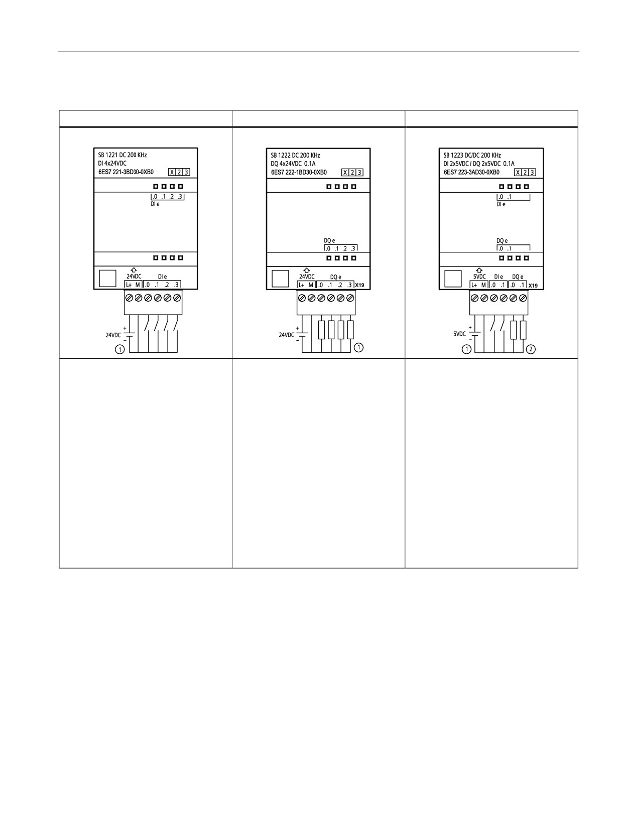
Table A- 17 Wiring diagrams for digital SBs
SB 1221 input module
SB 1222 output module
SB 1223 input/output module
SB 1221 DI 4 (200 kHz)
SB 1222 DQ 4 (200 kHz)
SB 1223 DI 2 / DQ 2 (200 kHz)
① Supports sourcing inputs only.
① For sourcing outputs, connect
① Supports sourcing inputs only.
"Load" to "-" (shown). For sinking out-
② For sourcing outputs, connect
puts, connect "Load" to "+". Because
"Load" to "-" (shown). For sinking out-
both sinking and sourcing configura-
puts, connect "Load" to "+". Because
tions ae supported by the same circuit-
both sinking and sourcing configura-
ry, the active state of a sourcing load is
tions are supported by the same circuit-
opposite that of a sinking load. A
ry, the active state of a sourcing load is
source output exhibits positive logic (Q
opposite that of a sinking load. A
bit and LED are ON when the load has
source output exhibits positive logic (Q
current flow), while a sink output exhib-
bit and LED are ON when the load has
its negative logic (Q bit and LED are
current flow), while a sink output exhib-
OFF when the load has current flow). If
its negative logic (Q bit and LED are
the module is plugged in with no user
OFF when the load has current flow). If
program, the default for this module is
the module is plugged in with no user
0 V, which means that a sinking load
program, the default for this module is
will be turned ON.
0 V, which means that a sinking load
will be turned ON.
377
Technical specifications
A.3 Digital I/O modules
Note
The high-speed (200 kHz) SBs (SB 1221 and SB 1223) support only sinking inputs. The
standard SB 1223 supports only sourcing inputs.
The high-speed (200 kHz) outputs (SB 1222 and SB 1223) can be either sourcing or sinking.
For sourcing outputs, connect "Load" to "-" (shown). For sinking outputs, connect "Load" to
"+". Because both sinking and sourcing configurations are supported by the same circuitry,
the active state of a sourcing load is opposite that of a sinking load. A source output exhibits
positive logic (Q bit and LED are ON when the load has current flow), while a sink output
exhibits negative logic (Q bit and LED are OFF when the load has current flow). If the
module is plugged in with no user program, the default for this module is 0 V, which means
that a sinking load will be turned ON.
A.3.2
SM 1221 digital input (DI)
Table A- 18 SM 1221 digital input (DI)
Technical data
SM 1221 DI 8 24 VDC
SM 1221 DI 16 24 VDC
Article number
6ES7 221-1BF32-0XB0
6ES7 221-1BH32-0XB0
Number of inputs (DI)
8
16
See specifications (Page 384).
Dimensions W x H x D (mm)
45 x 100 x 75
45 x 100 x 75
Weight
170 grams
210 grams
Power dissipation
1.5 W
2.5 W
Current consumption
SM Bus
105 mA
130 mA
24 VDC
4 mA / input used
4 mA / input used
378
Technical specifications
A.3 Digital I/O modules
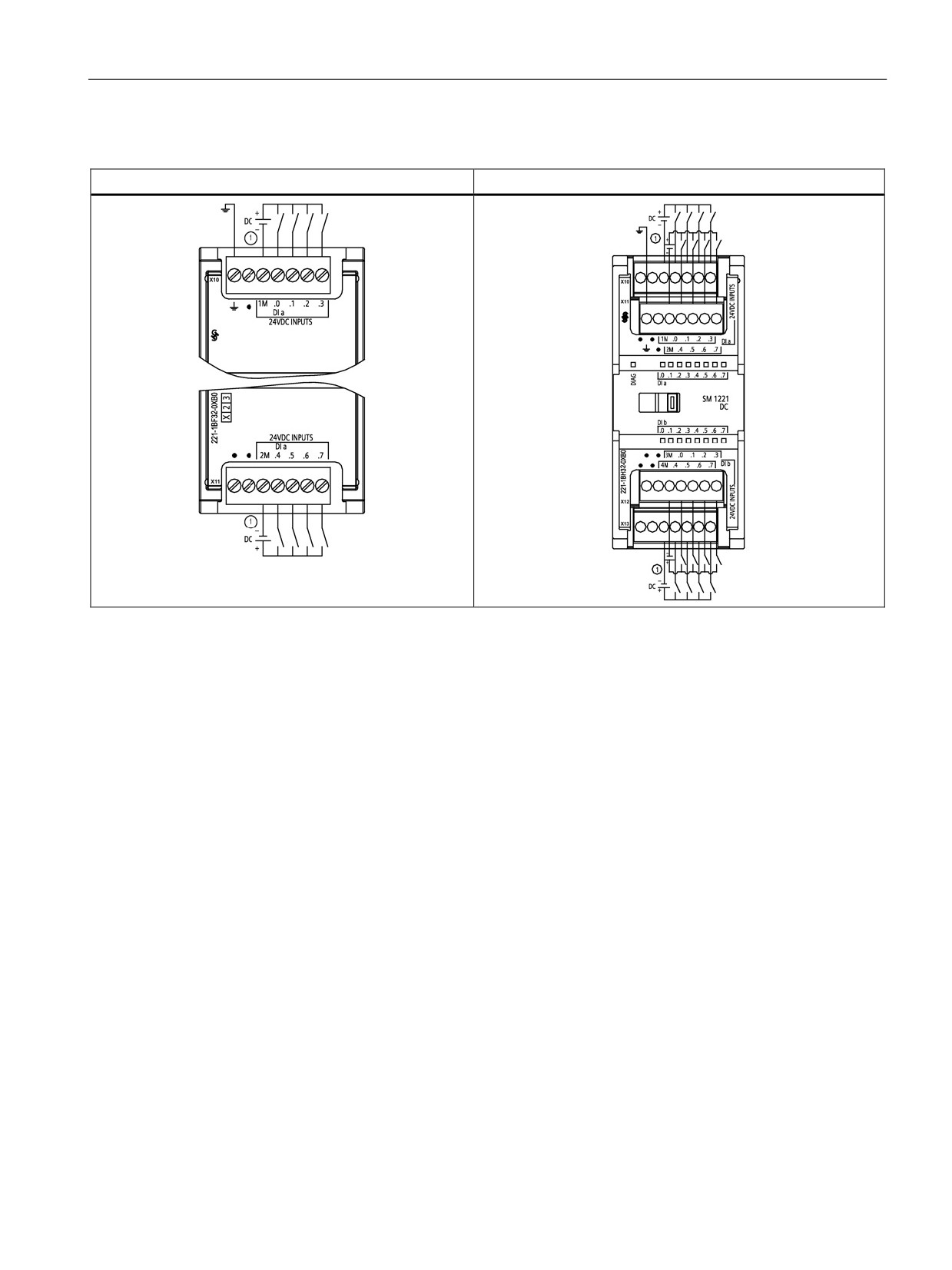
Table A- 19 Wiring diagram for SM 1221 digital input (DI) modules
SM 1221 DI 8 (24 VDC)
SM 1221 DI 16 (24 VDC)
① For sinking inputs, connect "-" to "M" (shown). For sourcing inputs connect "+" to "M".
379
Technical specifications
A.3 Digital I/O modules
A.3.3
SM 1222 digital output (DQ)
Table A- 20 SM 1222 digital output (DQ)
Technical data
SM 1222 DQ (Relay)
SM 1222 DQ (24 VDC)
Article number
•
DQ 8: 6ES7 222-1HF32-0XB0
•
DQ 8: 6ES7 222-1BF32-0XB0
•
DQ 8: Changeover: 6ES7 222-
•
DQ 16: 6ES7 222-1BH32-0XB0
1XF32-0XB0
•
DQ 16: 6ES7 222-1HH32-0XB0
Number of outputs (DQ)
•
8 (DQ 8 and DQ 8 Changeover)
•
8 (DQ 8)
See specifications (Page 384).
•
16 (DQ 16)
•
16 (DQ 16)
Dimensions W x H x D (mm)
•
DQ 8 and DQ 16: 45 x 100 x 75
45 x 100 x 75
•
DQ 8 Changeover: 70 x 100 x 75
Weight
•
DQ 8: 190 grams
• DQ 8: 180 grams
•
DQ 8 Changeover: 310 grams
• DQ 16: 220 grams
•
DQ 16: 260 grams
Power dissipation
•
DQ 8: 4.5 W
• DQ 8: 1.5 W
•
DQ 8 Changeover: 5 W
• DQ 16: 2.5 W
•
DQ 16: 8.5 W
Current consumption
SM Bus
•
DQ 8: 120 mA
• DQ 8: 120 mA
•
DQ 8 Changeover: 140 mA
• DQ 16: 140 mA
•
DQ 16: 135 mA
24 VDC
•
DQ 8 and DQ 16:11 mA / Relay coil
• DQ 8: --
used
• DQ 16: --
•
DQ 8 Changeover: 16.7 mA Relay
coil used
380
Technical specifications
A.3 Digital I/O modules
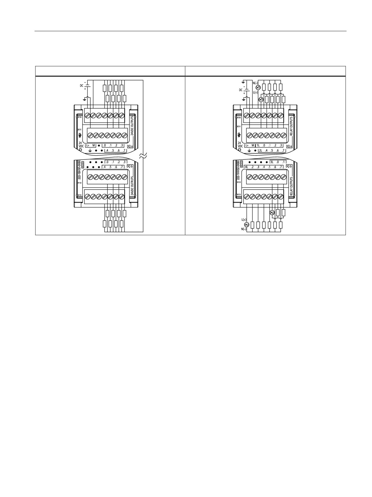
Table A- 21 Wiring diagram for SM 1222 digital output (DQ) modules
SM 1222 DQ 16, 24 VDC
SM 1222 DQ 16, Relay output
381
Technical specifications
A.3 Digital I/O modules
A.3.4
SM 1223 VDC digital input/output (DI / DQ)
Table A- 22 SM 1223 combination digital input / output (DI / DQ)
Technical data
SM 1223 DI (24 VDC) / DQ (Relay)
SM 1223 DI (24 VDC) / DQ (24 VDC)
Article number
DI 8 / DQ 8: 6ES7 223-1PH32-0XB0
DI 8 / DQ 8: 6ES7 223-1BH32-0XB0
DI 16 / DQ 16: 6ES7 223-1PL32-0XB0
DI 8 / DQ 8: 6ES7 223-1BL32-0XB0
Number of inputs / outputs (DI
• Inputs: 8 or 16 (24 VDC)
• Inputs: 8 or 16 (24 VDC)
/ DQ)
• Outputs: 8 or 16 (relay)
• Outputs: 8 or 16 (24 VDC)
See specifications (Page 384).
Dimensions W x H x D
• DI 8 / DQ 8: 45 x 100 x 75
• DI 8 / DQ 8: 45 x 100 x 75
(mm)
• DI 16 / DQ 16: 70 x 100 x 75
• DI 16 / DQ 16: 70 x 100 x 75
Weight
• DI 8 / DQ 8: 230 grams
• DI 8 / DQ 8: 210 grams
• DI 16 / DQ 16: 350 grams
• DI 16 / DQ 16: 310 grams
Power dissipation
• DI 8 / DQ 8: 5.5 W
• DI 8 / DQ 8: 2.5 W
• DI 16 / DQ 16: 10 W
• DI 16 / DQ 16: 4.5 W
Current con-
SM Bus
• DI 8 / DQ 8: 145 mA
• DI 8 / DQ 8: 145 mA
sumption
• DI 16 / DQ 16: 180 mA
• DI 16 / DQ 16: 185 mA
24 VDC
4 mA / input used
4 mA / input used
11 mA / Relay coil used
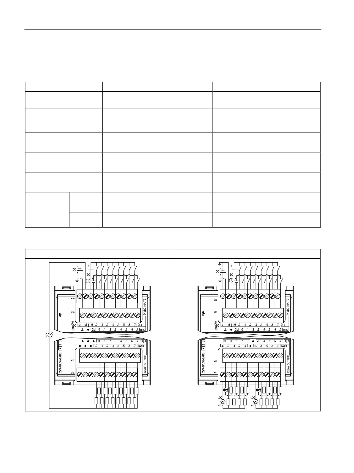
Table A- 23 Wiring diagram for SM 1223 combination DI / DQ modules
SM 1223 DI 16 (24 VDC) / DQ 16 (24 VDC)
SM 1223 DI 16 (24 VDC) / DQ 16 (Relay)
① For sinking inputs, connect "-" to "M" (shown). For sourcing inputs, connect "+" to "M".
382
Technical specifications
A.3 Digital I/O modules
A.3.5
SM 1223 120/230 VAC input / Relay output
Table A- 24 SM 1223 combination VAC digital input / output (DI / DQ)
Technical data
SM 1223 DI (120/230 VAC) / DQ (Relay)
Article number
DI 8 / DQ 8: 6ES7 223-1QH32-0XB0
Number of inputs / outputs (DI / DQ)
Inputs: 8 (120/230 VAC)
See the specifications for 120/230 VAC inputs (Page 386).
Outputs: 8 (relay)
See the specifications for the digital outputs (Page 387).
Dimensions W x H x D (mm)
45 x 100 x 75
Weight
190 grams
Power dissipation
7.5 W
Current con-
SM Bus
120 mA
sumption
24 VDC
11 mA / relay coil used
Note
The SM 1223 DI 8 x 120/230 VAC, DQ 8 x Relay signal module (6ES7 223-1QH32-0XB0) is
approved for use in Class 1, Division 2, Gas Group A, B, C, D, Temperature
Class T4 Ta = 40 °C.
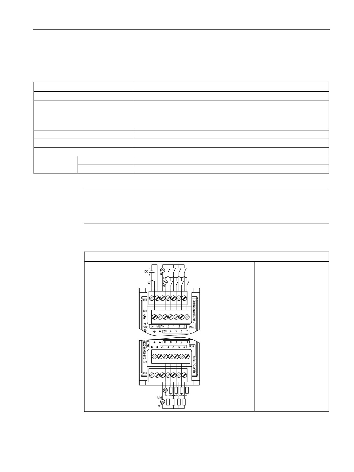
Table A- 25 Wiring diagram for SM 1223 DI 8 (120/230 VAC) / DQ 8 (Relay)
SM 1223 DI 8 (120/230 VAC) / DQ 8 (Relay)
383
Technical specifications
A.4 Specifications for the digital inputs and outputs
A.4
Specifications for the digital inputs and outputs
A.4.1
24 VDC digital inputs (DI)
Table A- 26 Specifications for the digital inputs (DI)
Technical data
CPU, SM and SB
High-speed SB (200 kHz)
Type
• CPU and SM: IEC Type 1 sink
SB 1221 200 kHz and SB 1223 200 kHz:
Source
(Sink/Source)
• SB 1223: IEC Type 1 sink
(Sink only)
Rated voltage
24 VDC at 4 mA, nominal
24 VDC SB: 24 VDC at 7 mA, nominal
5 VDC SB: 5 VDC at 15 mA, nominal
Continuous permissible
30 VDC, max.
24 VDC SB: 28.8 VDC
voltage
5 VDC SB: 6 VDC
Surge voltage
35 VDC for 0.5 sec.
24 VDC SB: 35 VDC for 0.5 sec
5 VDC SB: 6 V
Logic 1 signal (min.)
15 VDC at 2.5 mA
24 VDC SB: L+ minus 10 VDC at 2.9 mA
5 VDC SB: L+ minus 2.0 VDC at 5.1 mA
Logic 0 signal (max.)
5 VDC at 1 mA
24 VDC SB: L+ minus 5 VDC at 1.4 mA
5 VDC SB: L+ minus 1.0 VDC at 2.2 mA
Isolation (field side to logic)
500 VAC for 1 minute
500 VAC for 1 minute
Isolation groups
• CPU: 1
• SB 1221 DI 4: 1
• SM 1221 DI 8: 2
• SB 1223 DI 2: 1
• SM 1221 DI 16: 4
• SB 1223 DI 2: 1
• SM 1223: 2
Filter times
0.2, 0.4, 0.8, 1.6, 3.2, 6.4, and 12.8 ms (se-
0.2, 0.4, 0.8, 1.6, 3.2, 6.4, and 12.8 ms (se-
lectable in groups of 4)
lectable in groups of 4)
384
Technical specifications
A.4 Specifications for the digital inputs and outputs
Technical data
CPU, SM and SB
High-speed SB (200 kHz)
Number of inputs on simul-
•
SM 1221 and SM 1223 DI 8: 8
• SB 1221 DI 4: 4
taneously
• SM 1221 and SM 1223 DI 16: 16
• SB 1223 DI 2: 2
• SB 1223 DI 2: 2
• CPU 1211C: 6 at 60 °C horizontal or 50
°C vertical
• CPU 1212C: 4 (no adjacent points) at 60
°C horizontal or 50 °C vertical; 8 at 55 °C
horizontal or 45 °C vertical
• CPU 1214C, CPU 1215C: 7 (no adjacent
points) at 60 °C horizontal or 50 °C verti-
cal; 14 at 55 °C horizontal or 45 °C verti-
cal
• CPU 1217C: 5 Sink/source inputs (no
adjacent points) and 4 differential inputs
at 60 °C horizontal or 50 °C vertical; 14
at 55 °C horizontal or 45 °C vertical
Cable length (meters)
•
500 m shielded, 300 m unshielded
50 m shielded twisted pair
• CPU: 50 m shielded for HSC
Note
When switching frequencies above 20 kHz, it is important that the digital inputs receive a
square wave. Consider the following options to improve the signal quality to the inputs:
• Minimize the cable length
• Change a driver from a sink only driver to a sinking and sourcing driver
• Change to a higher quality cable
• Reduce the circuit/components from 24 V to 5 V (if the product is rated for low voltage
operation. Refer to complete specifications in the S7-1200 Programmable Controller
System Manual)
• Add an external load at the input
385
Technical specifications
A.4 Specifications for the digital inputs and outputs
Table A- 27 HSC clock input rates (max.)
Technical data
Single phase
Quadrature phase
CPU 1211C
100 kHz
80 kHz
CPU 1212C
100 kHz (Ia.0 to Ia.5) and
80 kHz (Ia.0 to Ia.5) and
30 kHz (Ia.6 to Ia.7)
20 kHz (Ia.6 to Ia.7)
CPU 1214C, CPU 1215C
100 kHz (Ia.0 to Ia.5) and
80 kHz (Ia.0 to Ia.5) and
30 kHz (Ia.6 to Ib.5)
20 kHz (Ia.6 to Ib.5)
CPU 1217C
1 MHz (Ib.2 to Ib.5)
1 MHz (Ib.2 to Ib.5)
100 kHz (Ia.0 to Ia.5)
80 kHz (Ia.0 to Ia.5)
30 kHz (Ia.6 to Ib.1)
20 kHz (Ia.6 to Ib.1)
High-speed (200 kHz) SB
200 kHz
160 kHz
Standard-speed SB
30 kHz
20 kHz
1
Logic 1 level = 15 to 26 VDC
A.4.2
120/230 VAC digital AC inputs
Table A- 28
120/230 VAC digital inputs
Technical data
SM
Type
IEC Type 1
Rated voltage
120 VAC at 6 mA, 230 VAC at 9 mA
Continuous permissible voltage
264 VAC
Surge voltage
--
Logic 1 signal (min.)
79 VAC at 2.5 mA
Logic 0 signal (max.)
20 VAC at 1 mA
Leakage current (max.)
1 mA
Isolation (field side to logic)
1500 VAC for 1 minute
Isolation groups1
4
Input delay times
• Typical: 0.2 to 12.8 ms, user selectable
• Maximum: --
Connection of 2 wire proximity sensor (Bero) (max.)
1 mA
Cable length
Unshielded
300 meters
Shielded
500 meters
Number of inputs on simultaneously
8
1
Channels within a group must be of the same phase.
386
Technical specifications
A.4 Specifications for the digital inputs and outputs
A.4.3
Digital outputs (DQ)
Table A- 29 Specifications for the digital outputs (DQ)
Technical data
Relay
24 VDC
200 kHZ 24 VDC
(CPU and SM)
(CPU, SM, and SB)
(SB)
Type
Relay, dry contact
Solid state - MOSFET (Source)
Solid state - MOSFET
(Sink/Source)
Voltage range
5 to 30 VDC or
20.4 to 28.8 VDC
20.4 to 28.8 VDC 1
5 to 250 VAC
4.25 to 6.0 VDC 2
Logic 1 signal at max. current
--
20 VDC min.
L+ minus 1.5 V 1
L+ minus 0.7 V 2
Logic 0 signal with 10 KΩ load
--
CPU: 20 VDC min.,
1.0 VDC, max. 1
0.1 VDC max.
0.2 VDC, max. 2
SB: 0.1 VDC max.
SM DC: 0.1 VDC max.
Current (max.)
2.0 A
0.5 A
0.1 A
Lamp load
30 W DC / 200 W AC
SB: 5 W
--
ON state resistance
0.2 Ω max. when new
0.6 Ω max.
11 Ω max. 1 or 7 Ω
max. 2
OFF state resistance
--
--
6 Ω max. 1 or 0.2 Ω
max. 2
Leakage current per point
--
10 μA max.
--
Pulse Train Output rate
CPU: N/A3
CPU: 100 kHz max.,2 Hz min.4
200 kHz max., 2 Hz
min.
SB: 20 kHz max., 2 Hz min.5
Surge current
7 A with contacts closed
CPU: 8 A for 100 ms max.
0.11 A
SB: 5 A for 100 ms max.
SM: 8 A for 100 ms max.
Overload protection
No
No
No
Isolation (field side to logic)
Coil to contact: 1500 VAC
500 VAC for 1 minute
500 VAC for 1 minute
for 1 minute
Coil to logic: None
Isolation groups
• CPU 1211C: 1
• CPU: 1
15
• CPU 1212C: 2
• SB: 1
• CPU 1214C: 2
• SM (DQ 8): 1
• CPU 1215C: 2
• SM (DQ 16): 1
• SM DQ 8: 2
• SM DQ 8 Changeover: 8
• SM DQ 16: 4
Isolation resistance
100 MΩ min. when new
--
--
Isolation between open con-
750 VAC for 1 minute
--
--
tacts
Number of outputs on simulta-
CPU 1211C: 4 at 60 °C horizontal or 50 °C vertical
--
neously
CPU 1212C: 3 (no adjacent points) at 60 °C horizontal or 50 °C
--
vertical;
6 at 55 °C horizontal or 45 °C vertical
387
Technical specifications
A.4 Specifications for the digital inputs and outputs
Technical data
Relay
24 VDC
200 kHZ 24 VDC
(CPU and SM)
(CPU, SM, and SB)
(SB)
CPU 1214C: 5 (no adjacent points) at 60 °C horizontal or 50 °C
--
vertical;
10 at 55 °C horizontal or 45 °C vertical
CPU 1215C: 5 (no adjacent points) at 60 °C horizontal or 50 °C
--
vertical; 10 at 55 °C horizontal or 45 °C vertical
CPU 1217C: 3 Solid state - MOSFET (sourcing) outputs (no
--
adjacent points) and 4 differential outputs at 60 °C horizontal or
50 °C vertical
10 at 55 °C horizontal or 45 °C vertical
SM 1222 DQ8: 8
SM 1222 DQ8: 8
--
SM1222 DQ 8 Changeover:
4 (no adjacent points) at 60
°C horizontal or 50 °C verti-
cal, 8 at 55 °C horizontal or
45 °C vertical
SM 1223 DI 8/DQ 8 Relay: 8
SM 1222 DQ16: 8 (no adja-
SM 1222 DQ16: 16
--
cent points) at 60 °C hori-
zontal or 50 °C vertical; 16
at 55 °C horizontal or 45 °C
vertical
SM 1223 DI 16/DQ 16 Re-
SM 1223 DI 8/DQ 8: 8
lay: 8 (no adjacent points) at
60 °C horizontal or 50 °C
vertical; 16 at 55 °C horizon-
tal or 45 °C vertical
SM 1223 DI 8 x 120/230
SM 1223 DI 16/DQ 16: 16
VAC/DQ 8 Relay: 4x SM
1223 DI 16/DQ 16 Relay: 4
(no adjacent points) at 60 °C
horizontal or 50 °C vertical;
8 at 55 °C horizontal or 45
°C vertical
SB 1223 DI 1 DQ 2, SM 1223 DI2
SB 1222 DQ 4: 2 (no
DQ2: 2
adjacent points) at 60
°C horizontal or 50 °C
vertical; 4 at 55 °C
horizontal or 45 °C
vertical
SB 1222 DQ 4 x 5
VDC: 4
SB 1223 D I 2/DQ 2: 2
SB 1223 DI 2/DQ 2: 2
388
Technical specifications
A.5 Analog I/O modules
Technical data
Relay
24 VDC
200 kHZ 24 VDC
(CPU and SM)
(CPU, SM, and SB)
(SB)
Current per common
SM Relay:
SM 24 VDC
--
• SM 1222 DQ 8 and DQ
• SM 1222 DQ 16: 8 A
16: 10 A
• SM 1223 DI 8/DQ 8: 4 A
• SM 1222 DQ 8 Change-
• SM 1223 DI 16/DQ 16: 8 A
over: 2A
• SM 1223 DI 8/DQ 8:10 A
• SM 1223 DI 16/DQ 16: 8
A
• SM 1223 DI 8x120/230
VAC/DQ 8 Rly: 10
Inductive clamp voltage
--
L+ minus 48 V,
None
1 W dissipation
Maximum relay switching
1 Hz
--
--
frequency
Switching delay
10 ms max.
CPU:
1.5 μs + 300 s rise 1
1.5 μs + 300 ns fall 1
• Qa.0 to Qa.3: 1.0 μs max., off-
200 ns + 300 ns rise 2
to-on 3.0 μs max., on-to-off
200 ns + 300 ns fall 2
• Qa.4 to Qb.1: 50 μs max., off-
to-on
200 μs max., on-to-off
SB: 2 μs max. off-to-on;
10 μs max. on-to-off
SM: 50 μs max. off-to-on
200 μs max. on-to-off
Lifetime mechanical (no load)
Relay: 10,000,000
--
--
open/close cycles
Lifetime contacts at rated load
Relay: 100,000 open/close
--
--
cycles
Behavior on RUN to STOP
Last value or substitute
Last value or substitute value
Last value or substitute
value (default value 0)
(default value 0)
value (default value 0)
Cable length (meters)
500 m shielded,
500 m shielded,
50 m shielded twisted
150 m unshielded
150 m unshielded
pair
1
24 VDC 200 kHz SB
2
5 VDC 200 kHz SB
3
For CPU models with relay outputs, you must install a digital signal board (SB) to use the pulse outputs.
4
Depending on your pulse receiver and cable, an additional load resistor (at least 10% of rated current) may improve
pulse signal quality and noise immunity.
5
SB 1223 200 kHz DI 2 / DQ 2: No isolation to inputs
389
Technical specifications
A.5 Analog I/O modules
A.5
Analog I/O modules
For a more complete list of modules available for S7-1200, refer to the S7-1200
Programmable Controller System Manual or to the customer support web site
A.5.1
SB 1231 and SB 1232 analog input (AI) and output (AQ)
Table A- 30 General specifications
Technical data
SB 1231 AI 1 x12 bit 1
SB 1232 AQ 1 x 12 bit
Article number
6ES7 231-4HA30-0XB0
6ES7 232-4HA30-0XB0
Dimensions W x H x D (mm)
38 x 62 x 21 mm
38 x 62 x 21 mm
Weight
35 grams
40 grams
Power dissipation
0.4 W
1.5 W
Current consumption (SM Bus)
55 mA
15 mA
Current consumption (24 VDC)
None
40 mA (no load)
Number of inputs / outputs
1
1
Type
Voltage or current (differential)
Voltage or current
1
To use the SB 1231 AI 1 x analog input, your CPU firmware must be V2.0 or higher.
Table A- 31 Wiring diagrams for the analog SBs
SB 1231 AI 1 x12 bit
SB 1232 AQ 1 x 12 bit
① Connect "R" and "0+" for current.
390
Technical specifications
A.5 Analog I/O modules
A.5.2
SM 1231 analog input (AI)
Table A- 32 SM 1231 analog inputs (AI)
Technical data
SM 1231 AI 4 x 13 bit
SM 1231 AI 8 x 13 bit
SM 1231 AI 4 x 16 bit
Article number (MLFB)
6ES7 231-4HD32-0XB0
6ES7 231-4HF32-0XB0
6ES7 231-5ND32-0XB0
Number of inputs
4 inputs (AI)
8 inputs (AI)
4 inputs
Type
Voltage or current (differ-
Voltage or current (differ-
Voltage or current (differ-
ential), selectable in
ential), selectable in
ential)
groups of 2
groups of 2
Dimensions W x H x D (mm)
45 x 100 x 75
45 x 100 x 75
45 x 100 x 75
Weight
180 grams
180 grams
180 grams
Power dissipation
1.5 W
1.5 W
1.8 W
Current consumption (SM Bus)
80 mA
90 mA
80 mA
Current consumption (24 VDC)
45 mA
45 mA
65 mA
A.5.3
SM 1232 analog output (AQ)
Table A- 33 SM 1232 analog outputs (AQ)
Technical data
SM 1232 AQ 2 x 14 bit
SM 1232 AQ 4 x 14 bit
Article number (MLFB)
6ES7 232-4HB32-0XB0
6ES7 232-4HD32-0XB0
Number and type of outputs
2 outputs (AQ)
4 outputs (AQ)
Dimensions W x H x D (mm)
45 x 100 x 75
45 x 100 x 75
Weight
180 grams
180 grams
Power dissipation
1.5 W
1.5 W
Current consumption (SM Bus)
80 mA
80 mA
Current consumption (24 VDC)
45 mA (no load)
45 mA (no load)
391
Technical specifications
A.5 Analog I/O modules
A.5.4
SM 1234 analog input/output (AI/AQ)
Table A- 34 SM 1234 combination analog input / output (AI / AQ)
Technical data
SM 1234 AI 4 x 13 bit / AQ 2 x 14 bit
Article number (MLFB)
6ES7 234-4HE32-0XB0
Number of inputs
4 inputs (AI)
Type
Voltage or current (differential), selectable in groups of 2
Number of outputs
2 outputs (AQ)
Type
Voltage or current (differential)
Dimensions W x H x D (mm)
45 x 100 x 75
Weight
220 grams
Power dissipation
2.0 W
Current consumption (SM Bus)
80 mA
Current consumption (24 VDC)
60 mA (no load)
A.5.5
Wiring diagrams for SM 1231 (AI), SM 1232 (AQ), and SM 1234 (AI/AQ)
Table A- 35 Wiring diagrams for the analog SMs
SM 1231 AI 8 x 13 bit
SM 1232 AQ 4 x 13 bit
SM 1234 AI 4 x13 bit / AQ2 x 14 bit
392
Technical specifications
A.5 Analog I/O modules
Note
Unused voltage input channels should be shorted.
Unused current input channels should be set to the 0 to 20 mA range and/or disable broken
wire error reporting.
Inputs configured for current mode will not conduct loop current unless the module is
powered and configured.
Current input channels will not operate unless external power is supplied to the transmitter.
393
Technical specifications
A.6 BB 1297 battery board
A.6
BB 1297 battery board
BB 1297 Battery Board
Table A- 36 General specifications
Technical data
BB 1297 Battery
Article number
6ES7 297-0AX30-0XA0
Dimensions W x H x D (mm)
38 x 62 x 21
Weight
28 grams
Hold up time real time clock
Approximately 1 year
Type of battery
CR10251
"Maint" LED of the CPU
Indicating a battery replacement is needed
User program
Application / system can evaluate battery status
1
Refer to the S7-1200 Programmable Controller System Manual, Chapter 2, Installation for information about installing
the BB 1297 or replacing a battery in the BB.
The BB 1297 Battery board is used for applications where the real time clock retention time
is beyond one month. Features of the BB 1297 Battery board are shown below:
● Supports time of day clock during PLC power off. The S7-1200 CPU, in combination with
the BB 1297 Battery board, supports the Time of Day clock retention during a power off
period of the application for up to one year.
● Only one BB 1297 Battery board or other SB can be used at a time.
● Hot plugging / hot swapping is not allowed. The BB 1297 Battery board is only
exchangeable or pluggable while the CPU is powered off. While the CPU is powered off,
and the BB 1297 is removed to exchange the actual battery, the internal super cap will
hold the time of day while the user replaces the battery.
● The CPU "Maint" LED indicates when a replacement battery is needed.
● The user program allows you to monitor or check on the status of the battery, and battery
board and allows a user message to be displayed on an HMI or web server.
394
Technical specifications
A.7 Specifications for the analog I/O
A.7
Specifications for the analog I/O
A.7.1
Specifications for the analog inputs (CPU, SM, and SB)
Table A- 37 Specifications for analog inputs (AI)
Technical data
CPU
SB
SM
Type
Voltage (single-ended)
Voltage or current (differen-
Voltage or current (differen-
tial)
tial), selectable in groups of 2
Range
0 to 10 V
±10 V, ±5 V, ±2.5,
±10 V, ±5 V, ±2.5 V,
0 to 20 mA, or
0 to 20 mA, or
4 mA to 20 mA
4 mA to 20 mA
Resolution
10 bits
11 bits + sign bit
12 bits + sign bit
Full scale range
0 to 27648
-27,648 to 27,648
-27,648 to 27,648
(data word)
Accuracy
3.0% / 3.5% of full-scale
±0.3% / ±0.6% of full scale
±0.1% / ±0.2% of full scale
(25 °C / -20 to 60 °C)
Overshoot / undershoot range
Voltage:
Voltage:
Voltage:
(data word)
27,649 to 32,511
32,511 to 27,649 /
32,511 to 27,649 /
-27,649 to -32,512
-27,649 to -32,512
(See note 1)
Current: N/A
Current:
Current:
32,511 to 27,649 /
32,511 to 27,649 /
0 to -4864
0 to -4864
Overflow / underflow (data
Voltage:
Voltage:
Voltage:
word)
32,512 to 32,767
32,767 to 32,512 /
32,767 to 32,512 /
-32,513 to -32,768
-32,513 to -32,768
(See note 1)
Current: N/A
Current:
Current:
32,767 to 32,512 /
32,767 to 32,512 /
-4865 to -32,768
-4865 to -32,768
Maximum withstand voltage /
35 VDC (voltage)
±35 V / ±40 mA
±35 V / ±40 mA
current
Smoothing
None, weak, medium, or
None, weak, medium, or
None, weak, medium, or
strong
strong
strong
(See note 2)
Noise rejection
10, 50, or 60 Hz
400, 60, 50, or 10 Hz
400, 60, 50, or 10 Hz
(See note 2)
Measuring principle
Actual value conversion
Actual value conversion
Actual value conversion
Common mode rejection
None
40 dB, DC to 60 Hz
40 dB, DC to 60 Hz
Operational signal range (sig-
Less than +12 V and great-
Less than +35 V and great-
Less than +12 V and greater
nal plus common mode volt-
er than 0 V
er than -35 V
than -12 V
age)
Load impedance
Single-ended: ≥100 KΩ
Differential:
Differential:
220 KΩ (voltage),
9 MΩ (voltage),
250 Ω (current)
250 Ω (current)
Common mode:
Common mode:
55 KΩ (voltage),
4.5 MΩ (voltage),
55 KΩ (current)
4.5 MΩ (current)
395
Technical specifications
A.7 Specifications for the analog I/O
Technical data
CPU
SB
SM
Isolation (field side to logic)
None
None
None
Cable length (meters)
100 m, shielded twisted pair
100 m, twisted and shielded
100 m twisted and shielded
Diagnostics
Overflow / underflow
Overflow / underflow
Overflow / underflow
24 VDC low voltage
Note 1: Refer to the analog input measurement ranges for voltage and current (Page 396) to determine the over-
shoot/undershoot and overflow/underflow ranges.
Note 2: Refer to the step response times (Page 398) to determine the smoothing and noise rejection values.
A.7.2
Input (AI) measurement ranges for voltage and current
Table A- 38 Analog input representation for voltage (SB and SM)
System
Voltage Measuring Range
Decimal
Hexadecimal
±10 V
±5 V
±2.5 V
±1.25 V
32767
7FFF1
11.851 V
5.926 V
2.963 V
1.481 V
Overflow
32512
7F00
32511
7EFF
11.759 V
5.879 V
2.940 V
1.470 V
Overshoot range
27649
6C01
27648
6C00
10 V
5 V
2.5 V
1.250 V
Rated range
20736
5100
7.5 V
3.75 V
1.875 V
0.938 V
1
1
361.7 μV
180.8 μV
90.4 μV
45.2 μV
0
0
0 V
0 V
0 V
0 V
-1
FFFF
-20736
AF00
-7.5 V
-3.75 V
-1.875 V
-0.938 V
-27648
9400
-10 V
-5 V
-2.5 V
-1.250 V
-27649
93FF
Undershoot range
-32512
8100
-11.759 V
-5.879 V
-2.940 V
-1.470 V
-32513
80FF
Underflow
-32768
8000
-11.851 V
-5.926 V
-2.963 V
-1.481 V
1
7FFF can be returned for one of the following reasons: overflow (as noted in this table), before valid values are availa-
ble(for example immediately upon a power up), or if a wire break is detected.
396
Technical specifications
A.7 Specifications for the analog I/O
Table A- 39
Analog input representation for current (SB and SM)
System
Current measuring range
Decimal
Hexadecimal
0 mA to 20 mA
4 mA to 20 mA
32767
7FFF
23.70 mA
22.96 mA
Overflow
32512
7F00
32511
7EFF
23.52 mA
22.81 mA
Overshoot range
27649
6C01
27648
6C00
20 mA
20 mA
Nominal range
20736
5100
15 mA
16 mA
1
1
723.4 nA
4 mA + 578.7 nA
0
0
0 mA
4 mA
-1
FFFF
Undershoot range
-4864
ED00
-3.52 mA
1.185 mA
-4865
ECFF
Underflow
-32768
8000
Table A- 40
Analog input representation for voltage (CPU 1215C and CPU 1217C)
System
Voltage Measuring Range
Decimal
Hexadecimal
0 to 10 V
32767
7FFF
11.851 V
Overflow
32512
7F00
32511
7EFF
11.759 V
Overshoot range
27649
6C01
27648
6C00
10 V
Rated range
20736
5100
7.5 V
34
22
12 mV
0
0
0 V
Negative values
Negative values are not sup-
ported
397
Technical specifications
A.7 Specifications for the analog I/O
A.7.3
Step response for the analog inputs (AI)
The following table shows the step response times for the analog inputs (AI) of the CPU, SB
and SM.
Table A- 41 Step response (ms) for the analog inputs
Smoothing selection (sample averaging)
Integration time selection
400 Hz (2.5 ms)
60 Hz (16.6 ms)
50 Hz (20 ms)
10 Hz (100 ms)
None (1 cycle):
CPU
N/A
63
65
130
No averaging
SB
4.5
18.7
22.0
102
SM
4
18
22
100
Weak (4 cycles):
CPU
N/A
84
93
340
4 samples
SB
10.6
59.3
70.8
346
SM
9
52
63
320
Medium (16 cycles):
CPU
N/A
221
258
1210
16 samples
SB
33.0
208
250
1240
SM
32
203
241
1200
Strong (32 cycles):
CPU
N/A
424
499
2410
32 samples
SB
63.0
408
490
2440
SM
61
400
483
2410
Sample rate
CPU
N/A
4.17
5
25
SB
0.156
1.042
1.250
6.250
A.7.4
Sample time and update times for the analog inputs
Table A- 42 Sample time and update time for SM and CPU
Rejection frequency (Integra-
Sample time
Update time for all channels
tion time)
4-channel SM
8-channel SM
CPU AI
400 Hz (2.5 ms)
0.625 ms 1
2.5 ms
10 ms
N/A ms
60 Hz (16.6 ms)
4.170 ms
4.17 ms
4.17 ms
4.17 ms
50 Hz (20 ms)
5.000 ms
5 ms
5 ms
5 ms
10 Hz (100 ms)
25.000 ms
25 ms
25 ms
25 ms
1
Sample rate for 8-channel SM is 1.250 ms.
398
Technical specifications
A.7 Specifications for the analog I/O
Table A- 43 Sample time and update time for SB
Rejection frequency (Integration time)
Sample time
SB update time
400 Hz (2.5 ms)
0.156 ms
0.156 ms
60 Hz (16.6 ms)
1.042 ms
1.042 ms
50 Hz (20 ms)
1.250 ms
1.25 ms
10 Hz (100 ms)
6.250 ms
6.25 ms
A.7.5
Specifications for the analog outputs
Table A- 44 Specifications for the analog outputs (SB and SM)
Technical data
SB
SM
Type
Voltage or current
Voltage or current
Range
±10 V, 0 to 20 mA, or 4 to 20 mA
±10 V, 0 to 20 mA, or 4 to 20 mA
Resolution
Voltage: 12 bits
Voltage: 14 bits
Current: 11 bits
Current: 13 bits
Full scale range
Voltage: -27,648 to 27,648
Voltage: -27,648 to 27,648
(data word)
Current: 0 to 27,648
Current: 0 to 27,648
(See note 1)
Accuracy
±0.5% / ±1% of full scale
±0.3% / ±0.6% of full scale
(25 °C / -20 to 60 °C)
Settling time
Voltage: 300 μS (R), 750 μS (1 uF)
Voltage: 300 μS (R), 750 μS (1 uF)
(95% of new value)
Current: 600 μS (1 mH), 2 ms (10 mH)
Current: 600 μS (1 mH), 2 ms (10 mH)
Load impedance
Voltage: ≥ 1000 Ω
Voltage: ≥ 1000 Ω
Current: ≤ 600 Ω
Current: ≤ 600 Ω
Behavior on RUN to STOP
Last value or substitute value (default val-
Last value or substitute value (default val-
ue 0)
ue 0)
Isolation
None
None
(field side to logic)
Cable length (meters)
100 m, twisted and shielded
100 m, twisted and shielded
Diagnostics
• Overflow / underflow
•
Overflow / underflow
• Short to ground (voltage mode only)
•
Short to ground (voltage mode only)
• Wire break (current mode only)
• Wire break (current mode only)
•
24 VDC low voltage
Note 1: Refer to the output ranges for voltage and current (Page 400) for the full-scale range.
399
Technical specifications
A.7 Specifications for the analog I/O
A.7.6
Output (AQ) measurement ranges for voltage and current
Table A- 45 Analog output representation for voltage (SB and SM)
System
Voltage Output Range
Decimal
Hexadecimal
± 10 V
32767
7FFF
See note 1
Overflow
32512
7F00
See note 1
32511
7EFF
11.76 V
Overshoot range
27649
6C01
27648
6C00
10 V
Rated range
20736
5100
7.5 V
1
1
361.7 μ V
0
0
0 V
-1
FFFF
-361.7 μ V
-20736
AF00
-7.5 V
-27648
9400
-10 V
-27649
93FF
Undershoot range
-32512
8100
-11.76 V
-32513
80FF
See note 1
Underflow
-32768
8000
See note 1
1
In an overflow or underflow condition, analog outputs will take on the substitute value of the STOP mode.
Table A- 46 Analog output representation for current (SB and SM)
System
Current output range
Decimal
Hexadecimal
0 mA to 20 mA
4 mA to 20 mA
32767
7FFF
See note 1
See note 1
Overflow
32512
7F00
See note 1
See note 1
32511
7EFF
23.52 mA
22.81 mA
Overshoot range
27649
6C01
27648
6C00
20 mA
20 mA
Rated range
20736
5100
15 mA
16 mA
1
1
723.4 nA
4 mA + 578.7 nA
0
0
0 mA
4mA
-1
FFFF
4 mA to 578.7 nA
Undershoot range
-6912
E500
0 mA
-6913
E4FF
Not possible. Output value limited to 0 mA.
-32512
8100
-32513
80FF
See note 1
See note 1
Underflow
-32768
8000
See note 1
See note 1
1
In an overflow or underflow condition, analog outputs will take on the substitute value of the STOP mode.
400
Technical specifications
A.7 Specifications for the analog I/O
Table A- 47 Analog output representation for current (CPU 1215C and CPU 1217C)
System
Current output range
Decimal
Hexadecimal
0 mA to 20 mA
32767
7FFF
See note 1
Overflow
32512
7F00
See note 1
32511
7EFF
23.52 mA
Overshoot range
27649
6C01
27648
6C00
20 mA
Rated range
20736
5100
15 mA
34
22
0.0247 mA
0
0
0 mA
Negative values
Negative values are not
supported
1
In an overflow condition, analog outputs will behave according to the device configuration properties settings. In the
"Reaction to CPU STOP" parameter, select either: "Use substitute value" or "Keep last value".
401

Technical specifications
A.8 RTD and Thermocouple modules
A.8
RTD and Thermocouple modules
The thermocouple (TC) modules (SB 1231 TC and SM 1231 TC) measure the value of
voltage connected to the analog inputs. This value can be either temperature from a TC or
volts.
● If voltage, the nominal range full scale value will be decimal 27648.
● If temperature, the value will be reported in degrees multiplied by ten (for example, 25.3
degrees will be reported as decimal 253).
The RTD modules (SB 1231 RTD and SM 1231 RTD) measure the value of resistance
connected to the analog inputs. This value can be either temperature or resistance.
● If resistance, the nominal range full scale value will be decimal 27648.
● If temperature, the value will be reported in degrees multiplied by ten (for example, 25.3
degrees will be reported as decimal 253).
The RTD modules support measurements with 2-wire, 3-wire and 4-wire connections to the
sensor resistor.
Note
The RTD and TC modules report 32767 on any activated channel with no sensor connected.
If open wire detection is also enabled, the module flashes the appropriate red LEDs.
Best accuracy will be achieved for the 10 Ω RTD ranges if 4 wire connections are used.
The resistance of the connection wires in 2 wire mode will cause an error in the sensor
reading, and therefore accuracy is not guaranteed.
Note
After power is applied, the module performs internal calibration for the analog-to-digital
converter. During this time the module reports a value of 32767 on each channel until valid
data is available on that channel. Your user program may need to allow for this initialization
time. Because the configuration of the module can vary the length of the initialization time,
you should verify the behavior of the module in your configuration. If required, you can
include logic in your user program to accommodate the initialization time of the module.
402
Technical specifications
A.8 RTD and Thermocouple modules
A.8.1
SB 1231 RTD and SB 1231 TC specifications
Note
To use these TC and RTD SBs, your CPU firmware must be V2.0 or higher.
Table A- 48 General specifications
Technical data
SB 1231 AI 1 x16 bit TC
SB 1231 AI 1 x 16 bit RTD
Article number
6ES7 231-5QA30-0XB0
6ES7 231-5PA30-0XB0
Dimensions W x H x D (mm)
38 x 62 x 21 mm
38 x 62 x 21 mm
Weight
35 grams
35 grams
Power dissipation
0.5 W
0.7 W
Current consumption (SM Bus)
5 mA
5 mA
Current consumption (24 VDC)
20 mA
25 mA
Number of inputs (Page 408)
1
1
Type
Floating TC and mV
Module-referenced RTD and Ω
Diagnostics
• Overflow / underflow1, 2
• Overflow / underflow1, 2
• Wire break3
• Wire break3
1
The overflow and underflow diagnostic alarm information will be reported in the analog data values even if the alarms
are disabled in the module configuration.
2
RTD: For resistance ranges, underflow detection is never enabled.
3
When wire break alarm is disabled and an open wire condition exists in the sensor wiring, the module may report ran-
dom values.
403
Technical specifications
A.8 RTD and Thermocouple modules
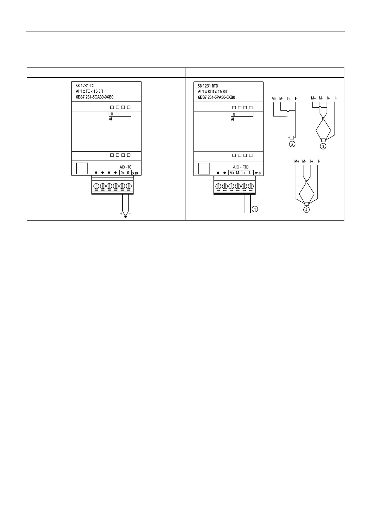
Table A- 49 Wiring diagrams for SB 1231 TC and RTD
SB 1231 AI 1 x 16 bit TC
SB 1231 AI 1 x 16 bit RTD
① Loop-back unused RTD input
② 2-wire RTD ③ 3-wire RTD ④ 4-wire RTD
404
Technical specifications
A.8 RTD and Thermocouple modules
A.8.2
SM 1231 RTD specifications
Table A- 50 General specifications
Technical data
SM 1231 AI 4 x RTD x 16 bit
SM 1231 AI 8 x RTD x 16 bit
Article number
6ES7 231-5PD32-0XB0
6ES7 231-5PF32-0XB0
Dimensions
45 x 100 x 75
70 x 100 x 75
W x H x D (mm)
Weight
220 grams
270 grams
Power dissipation
1.5 W
1.5 W
Current consumption
80 mA
90 mA
(SM Bus)
Current consumption 1
40 mA
40 mA
(24 VDC)
Number of inputs (Page 408)
4
8
Type
Module-referenced RTD and Ω
Module-referenced RTD and Ω
Diagnostics
• Overflow / underflow 2,3
• Overflow / underflow 2,3
•
24 VDC low voltage 2
•
24 VDC low voltage 2
• Wire break (current mode only) 4
• Wire break (current mode only) 4
1
20.4 to 28.8 VDC (Class 2, Limited Power, or sensor power from CPU)
2
The overflow, underflow and low voltage diagnostic alarm information will be reported in the analog data values even if
the alarms are disabled in the module configuration.
3
For resistance ranges underflow detection is never enabled.
4
When wire break alarm is disabled and an open wire condition exists in the sensor wiring, the module may report ran-
dom values.
405
Technical specifications
A.8 RTD and Thermocouple modules
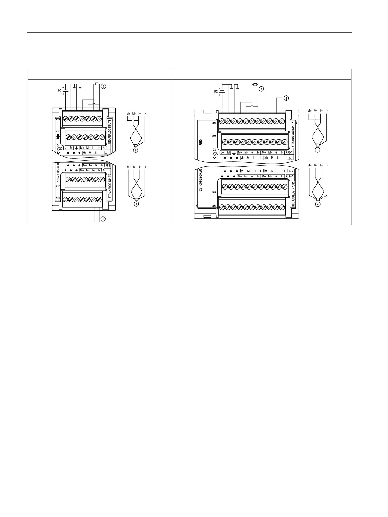
Table A- 51 Wiring diagrams for the RTD SMs
SM 1231 RTD 4 x 16 bit
SM 1231 RTD 8 x 16 bit
① Loop-back unused RTD inputs
② 2-wire RTD
③ 3-wire RTD
④ 4-wire RTD
Note: Connectors must be gold. See the S7-1200 Programmable Controller System Manual, Appendix C.
406
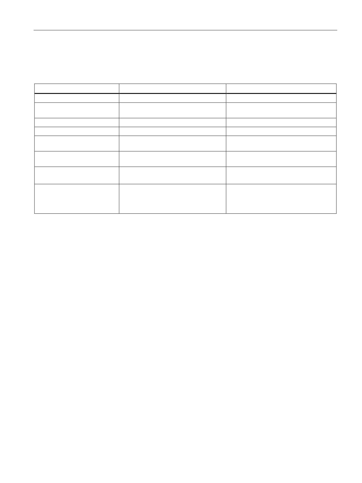
Technical specifications
A.8 RTD and Thermocouple modules
A.8.3
SM 1231 TC specifications
Table A- 52 General specifications
Model
SM 1231 AI 4 x 16 bit TC
SM 1231 AI 8 x 16 bit TC
Article number
6ES7 231-5QD32-0XB0
6ES7 231-5QF32-0XB0
Dimensions
45 x 100 x 75
45 x 100 x 75
W x H x D (mm)
Weight
180 grams
xxx grams
Power dissipation
1.5 W
1.5 W
Current consumption
80 mA
80 mA
(SM Bus)
Current consumption 1
40 mA
40 mA
(24 VDC)
Number of inputs (Page 408)
4
8
Type
Floating TC and mV
Floating TC and mV
Diagnostics
• Overflow / underflow 2
• Overflow / underflow 2
•
24 VDC low voltage 2
•
24 VDC low voltage 2
• Wire break (current mode only) 3
• Wire break (current mode only) 3
1
20.4 to 28.8 VDC (Class 2, Limited Power, or sensor power from CPU)
2
The overflow, underflow and low voltage diagnostic alarm information will be reported in the analog data values even if
the alarms are disabled in the module configuration.
3
When wire break alarm is disabled and an open wire condition exists in the sensor wiring, the module may report ran-
dom values.
407
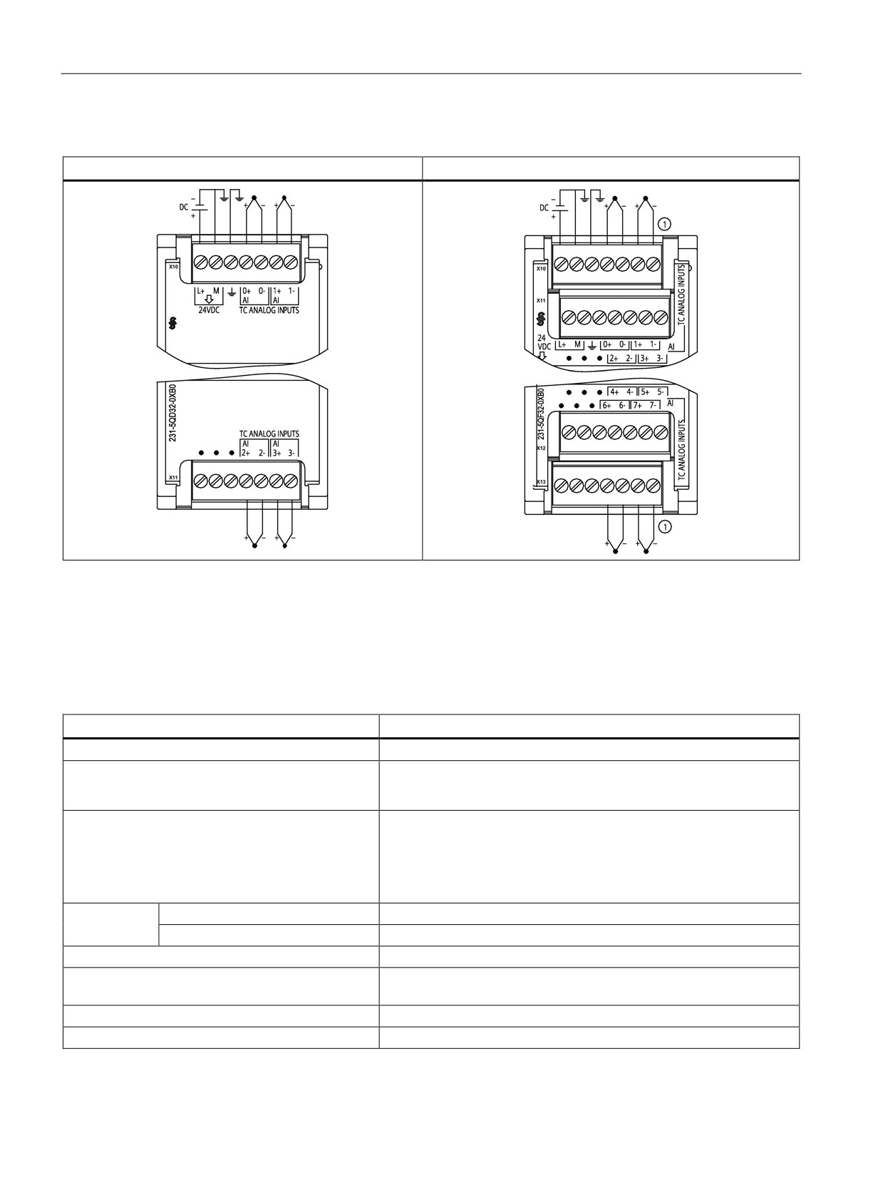
Technical specifications
A.8 RTD and Thermocouple modules
Table A- 53 Wiring diagrams for the TC SMs
SM 1231 AI 4 x 16 bit TC
SM 1231 AI 8 x 16 bit TC
① SM 1231 AI 8 TC: For clarity, TC 2, 3, 4, and 5 are not shown connected.
A.8.4
Analog input specifications for RTD and TC (SM and SB)
Table A- 54 Analog inputs for the RTD and TC modules (SB and SM)
Technical data
RTD and Thermocouple (TC)
Number of inputs
1 (SB), 4 or 8 (SM)
Type
• RTD: Module referenced RTD and Ω
• TC: Floating TC and mV
Range
See the RTD/TC type tables:
• Nominal range (data word)
• RTD (Page 411)
• Overshoot/undershoot range (data word)
• TC (Page 410)
• Overflow/underflow (data word)
Resolution
Temperature
0.1 °C / 0.1 °F
Resistance / voltage
15 bits plus sign
Maximum withstand voltage
± 35 V
Noise rejection
85 dB for the selected filter setting
(10 Hz, 50 Hz, 60 Hz or 400 Hz)
Common mode rejection
> 120 dB at 120 VAC
Impedance
≥ 10 MΩ
408
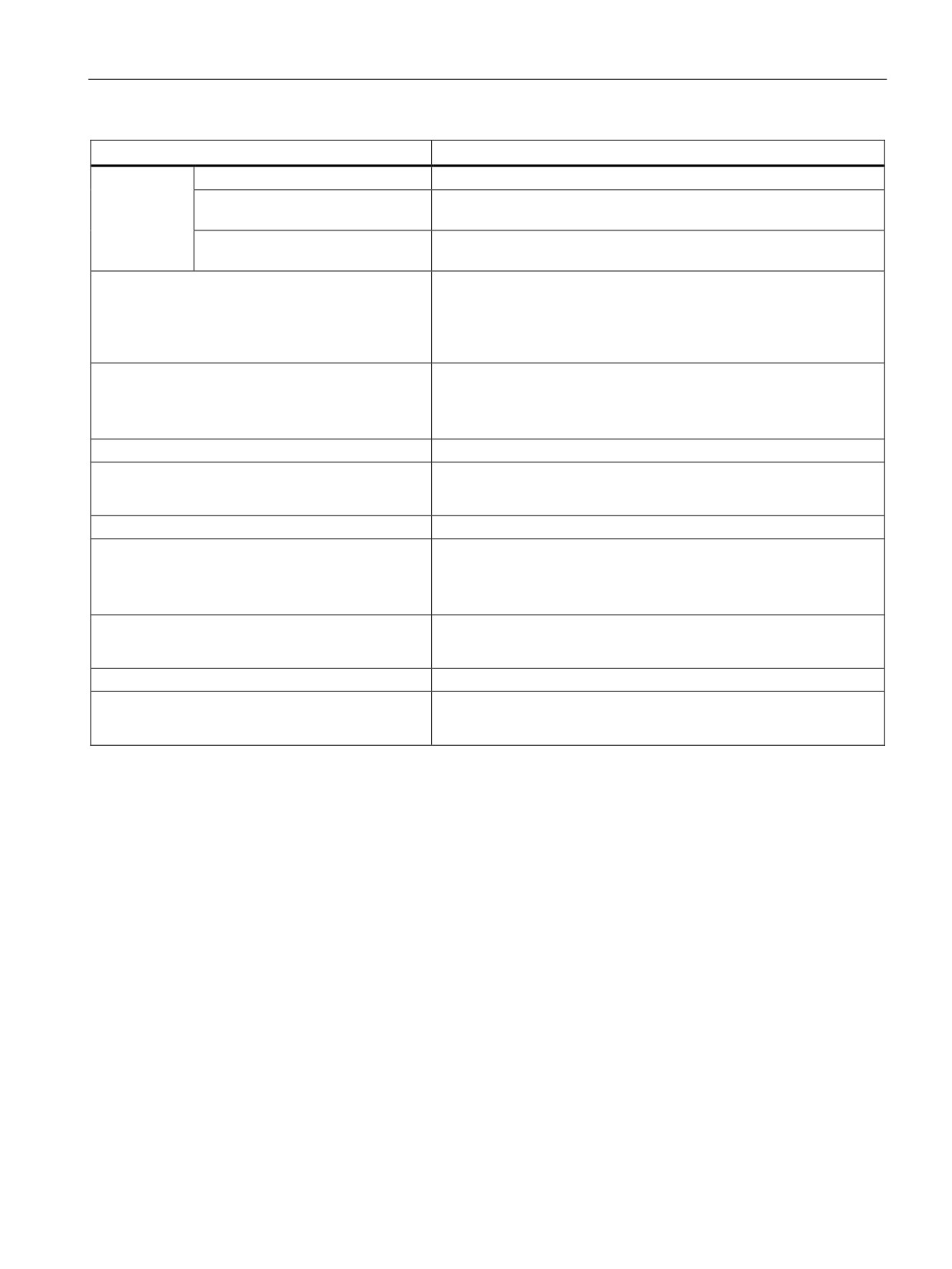
Technical specifications
A.8 RTD and Thermocouple modules
Technical data
RTD and Thermocouple (TC)
Isolation
Field side to logic
500 VAC
Field to 24 VDC
SM RTD and SM TC: 500 VAC
(Not applicable for SB RTD and SB TC)
24 VDC to logic
SM RTD and SM TC: 500 VAC
(Not applicable for SB RTD and SB TC)
Channel to channel isolation
• SM RTD: None
(Not applicable for SB RTD)
• SM TC: 120 VAC
(Not applicable for SB TC)
Accuracy (25 °C / -20 to 60 °C)
See the RTD/TC type tables:
• RTD (Page 411)
• TC (Page 410)
Repeatability
±0.05% FS
Maximum sensor dissipation
• RTD: 0.5 mW
• TC: Not applicable
Measuring principle
Integrating
Module update time
See the RTD/TC filter selection tables:
• RTD (Page 413)
• TC (Page 411)
Cold junction error
• RTD: Not applicable
• TC: ±1.5 °C
Cable length (meters)
100 meters to sensor max.
Wire resistance
• RTD: 20 Ω, 2.7 Ω for 10 Ω RTD max.
• TC: 100 Ω max.
409
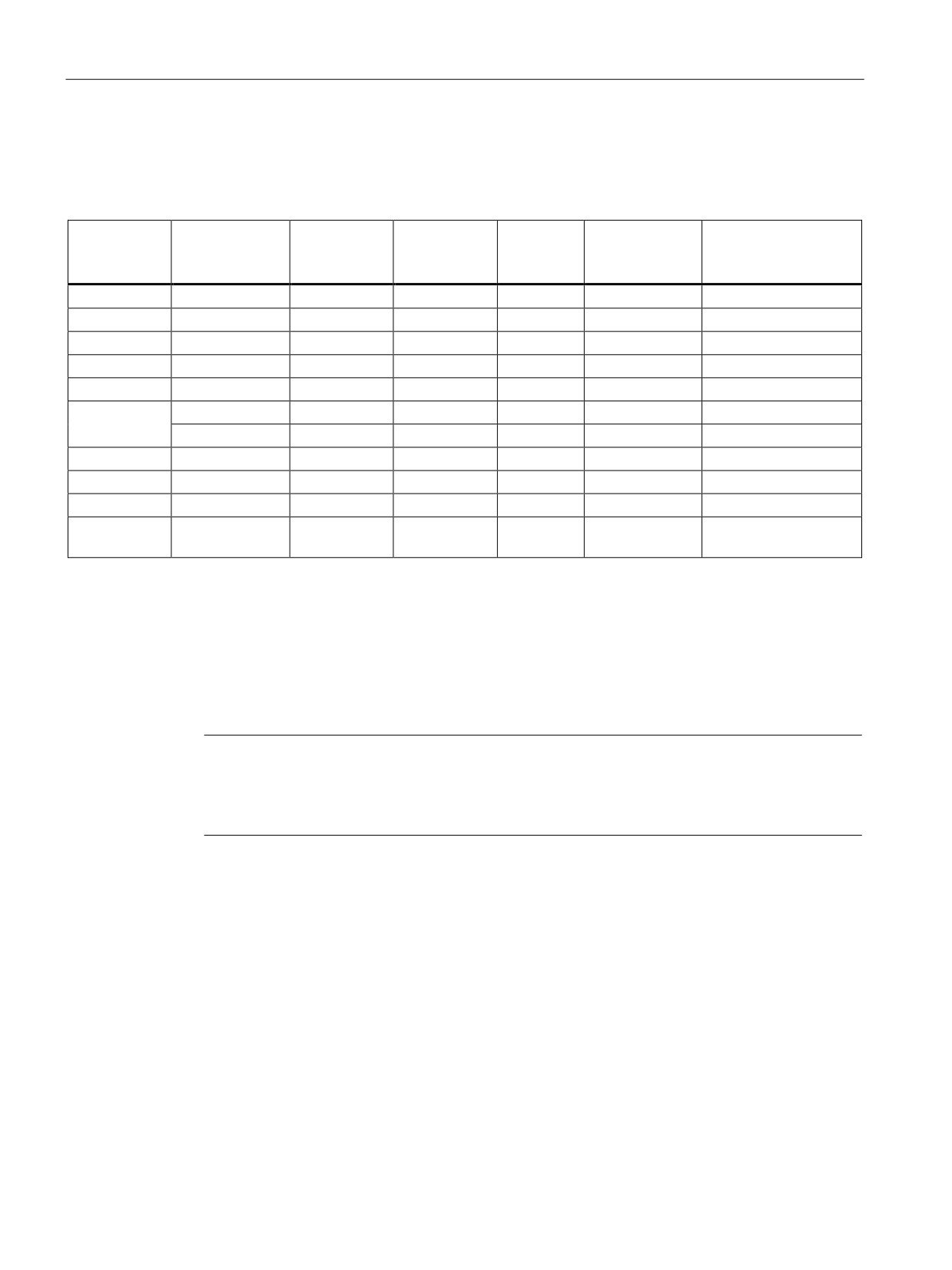
Technical specifications
A.8 RTD and Thermocouple modules
A.8.5
Thermocouple type
Table A- 55 Thermocouple type (ranges and accuracy)
Type
Under range
Nominal
Nominal
Over range
Normal range 3,
Normal range 3, 4 accu-
minimum1
range low limit
range high
maximum2
4 accuracy
racy -20 °C to 60 °C
limit
@ 25 °C
J
-210.0 °C
-150.0 °C
1200.0 °C
1450.0 °C
±0.3 °C
±0.6 °C
K
-270.0 °C
-200.0 °C
1372.0 °C
1622.0 °C
±0.4 °C
±1.0 °C
T
-270.0 °C
-200.0 °C
400.0 °C
540.0 °C
±0.5 °C
±1.0 °C
E
-270.0 °C
-200.0 °C
1000.0 °C
1200.0 °C
±0.3 °C
±0.6 °C
R & S
-50.0 °C
100.0 °C
1768.0 °C
2019.0 °C
±1.0 °C
±2.5 °C
B
0.0 °C
200.0 °C
800.0 °C
--
±2.0 °C
±2.5 °C
--
800.0 °C
1820.0 °C
1820.0 °C
±1.0 °C
±2.3 °C
N
-270.0 °C
-200.0 °C
1300.0 °C
1550.0 °C
±1.0 °C
±1.6 °C
C
0.0 °C
100.0 °C
2315.0 °C
2500.0 °C
±0.7 °C
±2.7 °C
TXK / XK(L)
-200.0 °C
-150.0 °C
800.0 °C
1050.0 °C
±0.6 °C
±1.2 °C
Voltage
-32512
-27648
27648
32511
±0.05%
±0.1%
-80 mV
80 mV
1
Thermocouple values below the under-range minimum value are reported as -32768.
2
Thermocouple values above the over-range minimum value are reported as 32767.
3
Internal cold junction error is ±1.5 °C for all ranges. This adds to the error in this table. The module requires at least 30
minutes of warm-up time to meet this specification.
4
For the 4-channel SM TC only: In the presence of radiated radio frequency of 970 MHz to 990 MHz, the accuracy may
be degraded.
Note
Thermocouple channel
Each channel on the Thermocouple signal module can be configured with a different
thermocouple type (selectable in the software during configuration of the module).
410
Technical specifications
A.8 RTD and Thermocouple modules
A.8.6
Thermocouple filter selection and update times
For measuring thermocouples, it is recommended that a 100 ms integration time be used.
The use of smaller integration times will increase the repeatability error of the temperature
readings.
Table A- 56 Thermocouple filter selection and update times
Rejection frequency
Integration time
Update time (seconds)
(Hz)
(ms)
1-channel SB
4-channel SM
8-channel SM
10
100
0.301
1.225
2.450
50
20
0.061
0.263
0.525
60
16.67
0.051
0.223
0.445
4001
10
0.031
0.143
0.285
1
To maintain module resolution and accuracy when 400 Hz rejection is selected, the integration time is 10 ms. This
selection also rejects 100 Hz and 200 Hz noise.
A.8.7
RTD sensor type selection table
Table A- 57 Ranges and accuracy for the different sensors supported by the RTD modules
Temperature coef-
RTD type
Under range
Nominal
Nominal
Over
Normal
Normal range
ficient
minimum1
range
range
range
range accu-
accuracy
low limit
high limit
maxi-
racy @
-20 °C to
mum2
25 °C
60 °C
Pt 0.003850
Pt 100 climat-
-145.00 °C
-120.00 °C
145.00 °C
155.00 °
±0.20 °C
±0.40 °C
ic
C
ITS90
DIN EN 60751
Pt 10
-243.0 °C
-200.0 °C
850.0 °C
1000.0 °
±1.0 °C
±2.0 °C
C
Pt 50
-243.0 °C
-200.0 °C
850.0 °C
1000.0 °
±0.5 °C
±1.0 °C
C
Pt 100
Pt 200
Pt 500
Pt 1000
Pt 0.003902
Pt 100
-243.0 °C
-200.0 °C
850.0 °C
1000.0 °
± 0.5 °C
±1.0 °C
Pt 0.003916
C
Pt 0.003920
Pt 200
-243.0 °C
-200.0 °C
850.0 °C
1000.0 °
± 0.5 °C
±1.0 °C
C
Pt 500
Pt 1000
Pt 0.003910
Pt 10
-273.2 °C
-240.0 °C
1100.0 °C
1295 °C
±1.0 °C
±2.0 °C
Pt 50
-273.2 °C
-240.0 °C
1100.0 °C
1295 °C
±0.8 °C
±1.6 °C
Pt 100
Pt 500
Ni 0.006720
Ni 100
-105.0 °C
-60.0 °C
250.0 °C
295.0 °C
±0.5 °C
±1.0 °C
Ni 0.006180
Ni 120
411
Technical specifications
A.8 RTD and Thermocouple modules
Temperature coef-
RTD type
Under range
Nominal
Nominal
Over
Normal
Normal range
ficient
minimum1
range
range
range
range accu-
accuracy
low limit
high limit
maxi-
racy @
-20 °C to
mum2
25 °C
60 °C
Ni 200
Ni 500
Ni 1000
LG-Ni 0.005000
LG-Ni 1000
-105.0 °C
-60.0 °C
250.0 °C
295.0 °C
±0.5 °C
±1.0 °C
Ni 0.006170
Ni 100
-105.0 °C
-60.0 °C
180.0 °C
212.4 °C
±0.5 °C
±1.0 °C
Cu 0.004270
Cu 10
-240.0 °C
-200.0 °C
260.0 °C
312.0 °C
±1.0 °C
±2.0 °C
Cu 0.004260
Cu 10
-60.0 °C
-50.0 °C
200.0 °C
240.0 °C
±1.0 °C
±2.0 °C
Cu 50
-60.0 °C
-50.0 °C
200.0 °C
240.0 °C
±0.6 °C
±1.2 °C
Cu 100
Cu 0.004280
Cu 10
-240.0 °C
-200.0 °C
200.0 °C
240.0 °C
±1.0 °C
±2.0 °C
Cu 50
-240.0 °C
-200.0 °C
200.0 °C
240.0 °C
±0.7 °C
±1.4 °C
Cu 100
1
RTD values below the under-range minimum value are reported as -32768.
2
RTD values above the over-range maximum value are reported as +32767.
Table A- 58 Resistance
Range
Under range
Nominal range
Nominal range
Over
Normal range
Normal range accura-
minimum
low limit
high limit
range
accuracy
cy -20 °C to 60 °C
maximum1
@ 25 °C
150 Ω
n/a
0 (0 Ω)
27648 (150 Ω)
176.383 Ω
±0.05%
±0.1%
300 Ω
n/a
0 (0 Ω)
27648 (300 Ω)
352.767 Ω
±0.05%
±0.1%
600 Ω
n/a
0 (0 Ω)
27648 (600 Ω)
705.534 Ω
±0.05%
±0.1%
1
Resistance values above the over-range maximum value are reported as 32767.
412
Technical specifications
A.8 RTD and Thermocouple modules
A.8.8
RTD filter selection and update times
Table A- 59 Filter selection and update times
Noise rejection fre-
Integration time
Update time (seconds)
quency (Hz)
(ms)
1-channel SB
4-channel SM
8-channel SM
10
100
4-/2-wire: 0.301
4-/2-wire: 1.222
4-/2-wire: 2.445
3-wire: 0.601
3-wire: 2.445
3-wire: 4.845
50
20
4-/2-wire: 0.061
4-/2-wire: 0.262
4-/2-wire: 0.525
3-wire: 0.121
3-wire: .505
3-wire: 1.015
60
16.67
4-/2-wire: 0.051
4-/2-wire: 0.222
4-/2-wire: 0.445
3-wire: 0.101
3-wire: 0.424
3-wire: 0.845
4001
10
4-/2-wire: 0.031
4-/2-wire: 0.142
4-/2-wire: 0.285
3-wire: 0.061
3-wire: 0.264
3-wire: 0.525
1
To maintain module resolution and accuracy when the 400 Hz filter is selected, the integration time is 10 ms. This selec-
tion also rejects 100 Hz and 200 Hz noise.
Note
The module reports 32767 on any activated channel with no sensor connected. If open wire
detection is also enabled, the module flashes the appropriate red LEDs.
Best accuracy will be achieved for the 10 Ω RTD ranges if 4 wire connections are used.
The resistance of the connection wires in 2 wire mode will cause an error in the sensor
reading and therefore accuracy is not guaranteed.
413
Technical specifications
A.9 Communication interfaces
A.9
Communication interfaces
For a more complete list of modules available for S7-1200, refer to the S7-1200
Programmable Controller System Manual or to the customer support web site
A.9.1
PROFIBUS master/slave
A.9.1.1
CM 1242-5 PROFIBUS DP SLAVE
Table A- 60 Technical specifications of the CM 1242-5
Technical specifications
Article number
6GK7 242-5DX30-0XE0
Interfaces
Connection to PROFIBUS
9-pin D-sub female connector
Maximum current consumption on the PROFIBUS interface
15 mA at 5 V (only for bus termination) *)
when connecting network components (for example optical
network components)
Permitted ambient conditions
Ambient temperature
• during storage
•
-40 °C to 70 °C
• during transportation
•
-40 °C to 70 °C
• during operation with a vertical installation (DIN rail hori-
•
0 °C to 55 °C
zontal)
• during operation with a horizontal installation (DIN rail
•
0 °C to 45 °C
vertical)
Relative humidity at 25 °C during operation, without conden-
95 %
sation, maximum
Degree of protection
IP20
Power supply, current consumption and power loss
Type of power supply
DC
Power supply from the backplane bus
5 V
Current consumption (typical)
150 mA
Effective power loss (typical)
0.75 W
Electrical isolation
710 VDC for 1 minute
• PROFIBUS interface to ground
• PROFIBUS interface to internal circuit
Dimensions and weights
• Width
•
30 mm
• Height
•
100 mm
• Depth
•
75 mm
414
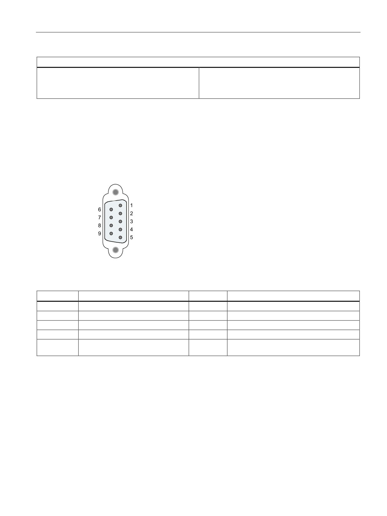
Technical specifications
A.9 Communication interfaces
Technical specifications
Weight
• Net weight
•
115 g
• Weight including packaging
•
152 g
*)The current load of an external consumer connected between VP (pin 6) and DGND (pin 5) must not exceed a maximum
of 15 mA (short-circuit proof) for bus termination.
A.9.1.2
Pinout of the D-sub socked of the CM 1242-5
PROFIBUS interface
Table A- 61 Pinout of the D-sub socket
Pin
Description
Pin
Description
1
- not used -
6
P5V2: +5V power supply
2
- not used -
7
- not used -
3
RxD/TxD-P: Data line B
8
RxD/TxD-N: Data line A
4
RTS
9
- not used -
5
M5V2: Data reference potential (ground
Housing
Ground connector
DGND)
415
Technical specifications
A.9 Communication interfaces
A.9.1.3
CM 1243-5 PROFIBUS DP Master
Table A- 62 Technical specifications of the CM 1243-5
Technical specifications
Article number
6GK7 243-5DX30-0XE0
Interfaces
Connection to PROFIBUS
9-pin D-sub female connector
Maximum current consumption on the PROFIBUS
15 mA at 5 V (only for bus termination) *)
interface when connecting network components
(for example optical network components)
Permitted ambient conditions
Ambient temperature
• during storage
•
-40 °C to 70 °C
• during transportation
•
-40 °C to 70 °C
• during operation with a vertical installation
•
0 °C to 55 °C
(DIN rail horizontal)
• during operation with a horizontal installation
•
0 °C to 45 °C
(DIN rail vertical)
Relative humidity at 25 °C during operation, with-
95 %
out condensation, maximum
Degree of protection
IP20
Power supply, current consumption and power loss
Type of power supply
DC
Power supply / external
24 V
• minimum
•
19.2 V
• maximum
•
28.8 V
Current consumption (typical)
• from 24 V DC
•
100 mA
• from the S7-1200 backplane bus
•
0 mA
Effective power loss (typical)
• from 24 V DC
•
2.4 W
• from the S7-1200 backplane bus
•
0 W
Power supply 24 VDC / external
• Min. cable cross section
•
min.: 0.14 mm2 (AWG 25)
• Max. cable cross section
•
max.: 1.5 mm2 (AWG 15)
• Tightening torque of the screw terminals
•
0.45 Nm (4 lb-in)
Electrical isolation
710 VDC for 1 minute
• PROFIBUS interface to ground
• PROFIBUS interface to internal circuit
416
Technical specifications
A.9 Communication interfaces
Technical specifications
Dimensions and weights
• Width
•
30 mm
• Height
•
100 mm
• Depth
•
75 mm
Weight
• Net weight
•
134 g
• Weight including packaging
•
171 g
*)The current load of an external consumer connected between VP (pin 6) and DGND (pin 5) must not
exceed a maximum of 15 mA (short-circuit proof) for bus termination.
Note
The CM 1243- (PROFIBUS master module) must eceive power from the 24 VDC sensor
supply of the CPU.
A.9.1.4
PROFIBUS master (CM 1243-5) requires 24 VDC power from the CPU
Note
The CM 1243-5 (PROFIBUS master module) must receive power from the 24 VDC sensor
supply of the CPU.
417
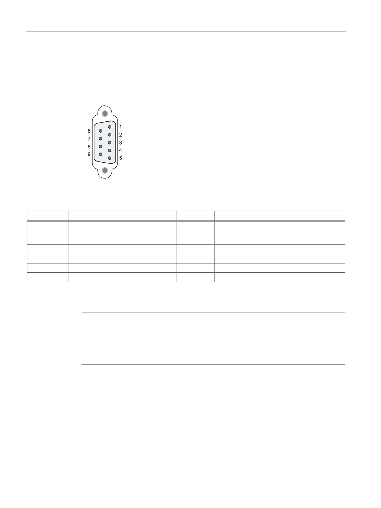
Technical specifications
A.9 Communication interfaces
A.9.1.5
Pinout of the D-sub socket of the CM 1243-5
PROFIBUS interface
Table A- 63 Pinout of the D-sub socket
Pin
Description
Pin
Description
1
- not used -
6
VP: Power supply +5 V only for bus terminating
resistors;
not for supplying external devices
2
- not used -
7
- not used -
3
RxD/TxD-P: Data line B
8
RxD/TxD-N: Data line A
4
CNTR-P: RTS
9
- not used -
5
DGND: Ground for data signals and VP
Housing
Ground connector
PROFIBUS cable
Note
Contacting the shield of the PROFIBUS cable
The shield of the PROFIBUS cable must be contacted.
To do this, strip the insulation from the end of the PROFIBUS cable and connect the shield
to functional earth.
418
Technical specifications
A.9 Communication interfaces
A.9.2
GPRS CP
Note
The CP 1242-7 is not approved for Maritime applications
The CP 1242-7 does not have Maritime approval.
Note
To use these modules, your CPU firmware must be V2.0 or higher.
A.9.2.1
CP 1242-7 GPRS
Table A- 64 Technical specifications of the CP 1242-7 GPRS V2
Technical specifications
Article number
6GK7 242-7KX3-0XE0
Wireless interface
Antenna connector
SMA socket
Nominal impedance
50 ohms
Wireless connection
Maximum transmit power
• GSM 850, class 4: +33 dBm ±2dBm
• GSM 900, class 4: +33 dBm ±2dBm
• GSM 1800, class 1: +30 dBm ±2dBm
• GSM 1900, class 1: +30 dBm ±2dBm
GPRS
Multislot class 10
device class B
coding scheme 1...4 (GMSK)
SMS
Mode outgoing: MO
service: point-to-point
Permitted ambient conditions
Ambient temperature
• during storage
•
-40 °C to 70 °C
• during transportation
•
-40 °C to 70 °C
• during operation with a vertical installation (DIN rail hori-
•
0 °C to 55 °C
zontal)
• during operation with a horizontal installation (DIN rail
•
0 °C to 45 °C
vertical)
Relative humidity at 25 °C during operation, without conden-
95 %
sation, maximum
Degree of protection
IP20
Power supply, current consumption and power loss
Type of power supply
DC
419
Technical specifications
A.9 Communication interfaces
Technical specifications
Power supply / external
24 V
• minimum
•
19.2 V
• maximum
•
28.8 V
Current consumption (typical)
• from 24 V DC
•
100 mA
• from the S7-1200 backplane bus
•
0 mA
Effective power loss (typical)
• from 24 V DC
•
2.4 W
• from the S7-1200 backplane bus
•
0 W
24 V DC power supply
• Min. cable cross section
•
min.: 0.14 mm2 (AWG 25)
• Max. cable cross section
•
max.: 1.5 mm2 (AWG 15)
• Tightening torque of the screw terminals
•
0.45 Nm (4 lb-in)
Electrical isolation
710 VDC for 1 minute
Power supply unit to internal circuit
Dimensions and weights
• Width
•
30 mm
• Height
•
100 mm
• Depth
•
75 mm
Weight
• Net weight
•
133 g
• Weight including packaging
•
170 g
420
Technical specifications
A.9 Communication interfaces
A.9.2.2
GSM/GPRS antenna ANT794-4MR
Technical specifications of the ANT794-4MR GSM/GPRS antenna
ANT794-4MR
Article number
6NH9860-1AA00
Mobile wireless networks
GSM/GPRS
Frequency ranges
•
824 to 960 MHz (GSM 850, 900)
•
1 710 to 1 880 MHz (GSM 1 800)
•
1 900 to 2 200 MHz (GSM / UMTS)
Characteristics
omnidirectional
Antenna gain
0 dB
Impedance
50 ohms
Standing wave ratio (SWR)
< 2,0
Max. power
20 W
Polarity
linear vertical
Connector
SMA
Length of antenna cable
5 m
External material
Hard PVC, UV-resistant
Degree of protection
IP20
Permitted ambient conditions
• Operating temperature
•
-40 °C through +70 °C
• Transport/storage temperature
•
-40 °C through +70 °C
• Relative humidity
•
100 %
External material
Hard PVC, UV-resistant
Construction
Antenna with 5 m fixed cable and SMA male
connector
Dimensions (D x H) in mm
25 x 193
Weight
• Antenna incl. cable
•
310 g
• Fittings
•
54 g
Installation
With supplied bracket
421
Technical specifications
A.9 Communication interfaces
A.9.2.3
Flat antenna ANT794-3M
Technical specifications of the flat antenna ANT794-3M
ANT794-3M
Article number
6NH9870-1AA00
Mobile wireless networks
GSM 900
GSM 1800/1900
Frequency ranges
890 - 960 MHz
1710 - 1990 MHz
Standing wave ratio (VSWR)
≤ 2:1
≤ 1,5:1
Return loss (Tx)
≈ 10 dB
≈ 14 dB
Antenna gain
0 dB
Impedance
50 ohms
Max. power
10 W
Antenna cable
HF cable RG 174 (fixed) with SMA male connector
Cable length
1.2 m
Degree of protection
IP64
Permitted temperature range
-40°C to +75°C
Flammability
UL 94 V2
External material
ABS Polylac PA-765, light gray (RAL 7035)
Dimensions (W x L x H) in mm
70.5 x 146.5 x 20.5
Weight
130 g
A.9.3
Teleservice (TS)
The following manuals contain the technical specification for the TS Adapter IE Basic and
the TS Adapter modular:
● Industrial Software Engineering Tools
Modular TS Adapter
● Industrial Software Engineering Tools
TS Adapter IE Basic
For more information about this product and for the product documentation, refer to the
product catalog web site for the TS Adapter
r%20IE%20basic&tab=).
422