Siemens simatic S7-1200. Manual (2015) - page 6
Motion control is easy
10.6 Operation of motion control for S7-1200
● Mode 3 - Active Referencing: This mode is the most precise method of Homing the Axis.
The initial direction and velocity of movement is configured in the Technology Object
Configuration Extended Parameters-Homing. This is dependent upon machine
configuration. There is also the ability to determine if the leading edge or falling edge of
the Reference Point Switch signal is the Home position. Virtually all sensors have an
active range and if the Steady State On position was used as the Home signal then there
would be a possibility for error in the Homing position since the On signal active range
would cover a range of distance. By using either the leading or falling edge of that signal
a much more precise Home position results. As with all other modes the value of the
Position input on the Homing instruction is added to the Hardware referenced position.
In active homing mode, the MC_Home instruction performs the required reference point
approach. When the reference point switch is detected, the axis is homed according to
the configuration. Active traversing motions are aborted.
Modes 0 and 1 do not require that the axis be moved at all. They are typically used in setup
and calibration. Modes 2 and 3 require that the axis move and pass a sensor that is
configured in the "Axis" technology object as the Reference Point Switch. The reference
point can be placed in the work area of the axis or outside of the normal work area but within
movement range.
10.6.3.2
Configuration of homing parameters
Configure the parameters for active and passive homing in the "Homing" configuration
window. The homing method is set using the "Mode" input parameter of the motion control
instruction. Here, Mode = 2 means passive homing and Mode = 3 means active homing.
Note
Use one of the following measures to ensure that the machine does not travel to a
mechanical endstop in the event of a direction reversal:
• Keep the approach velocity low
• Increase the configured acceleration/deceleration
• Increase the distance between hardware limit switch and mechanical stop
303

Motion control is easy
10.6 Operation of motion control for S7-1200
Table 10- 24 Configuration parameters for homing the axis
Parameter
Description
Input reference point switch
Select the digital input for the reference point switch from the drop-down list box. The
input must be interrupt-capable. The onboard CPU inputs and inputs of an inserted
(Active and passive homing)
signal board can be selected as inputs for the reference point switch.
The default filter time for the digital inputs is 6.4 ms. When the digital inputs are used
as a reference point switch, this can result in undesired decelerations and thus inac-
curacies. Depending on the reduced velocity and extent of the reference point switch,
the reference point may not be detected. The filter time can be set under "Input filter"
in the device configuration of the digital inputs.
The specified filter time must be less than the duration of the input signal at the refer-
ence point switch.
Auto reverse after reaching the
Activate the check box to use the hardware limit switch as a reversing cam for the
hardware limit switches
reference point approach. The hardware limit switches must be configured and acti-
vated for direction reversal.
(Active homing only)
If the hardware limit switch is reached during active homing, the axis brakes at the
configured deceleration (not with the emergency deceleration) and reverses direction.
The reference point switch is then sensed in reverse direction.
If the direction reversal is not active and the axis reaches the hardware limit switch
during active homing, the reference point approach is aborted with an error and the
axis is braked at the emergency deceleration.
Approach direction
With the direction selection, you determine the "approach direction" used during ac-
tive homing to search for the reference point switch, as well as the homing direction.
(Active and passive homing)
The homing direction specifies the travel direction the axis uses to approach the
configured side of the reference point switch to carry out the homing operation.
Reference point switch
• Active homing: Select whether the axis is to be referenced on the left or right side
(Active and passive homing)
of the reference point switch. Depending on the start position of the axis and the
configuration of the homing parameters, the reference point approach sequence
can differ from the diagram in the configuration window.
• Passive homing: With passive homing, the traversing motions for purposes of
homing must be implemented by the user via motion commands. The side of the
reference point switch on which homing occurs depends on the following factors:
- "Approach direction" configuration
- "Reference point switch" configuration
- Current travel direction during passive homing
Approach velocity
Specify the velocity at which the reference point switch is to be searched for during
the reference point approach.
(Active homing only)
Limit values (independent of the selected user unit):
Start/stop velocity ≤ approach velocity ≤ maximum velocity
304

Motion control is easy
10.6 Operation of motion control for S7-1200
Parameter
Description
Reduced velocity
Specify the velocity at which the axis approaches the reference point switch for hom-
ing.
(Active homing only)
Limit values (independent of the selected user unit):
Start/stop velocity ≤ reduced velocity ≤ maximum velocity
Home position offset
If the desired reference position deviates from the position of the reference point
switch, the home position offset can be specified in this field.
(Active homing only)
If the value does not equal 0, the axis executes the following actions following hom-
ing at the reference point switch:
1. Move the axis at reduced velocity by the value of the home position offset.
2. When the position of the home position offset is reached, the axis position is set
to the absolute reference position. The absolute reference position is specified via
parameter "Position" of motion control instruction "MC_Home".
Limit values (independent of the selected user unit):
-1.0e12 ≤ home position offset ≤ 1.0e12
Table 10- 25 Factors that affect homing
Influencing factors:
Result:
Configuration
Configuration
Current travel direction
Homing on
Approach direction
Reference point switch
Reference point switch
Positive
"Left (negative) side"
Positive direction
Left
Negative direction
Right
Positive
"Right (positive) side"
Positive direction
Right
Negative direction
Left
Negative
"Left (negative) side"
Positive direction
Right
Negative direction
Left
Negative
"Right (positive) side"
Positive direction
Left
Negative direction
Right
305
Motion control is easy
10.6 Operation of motion control for S7-1200
10.6.3.3
Sequence for active homing
You start active homing with motion control instruction "MC_Home" (input parameter
Mode = 3). Input parameter "Position" specifies the absolute reference point coordinates in
this case. Alternatively, you can start active homing on the control panel for test purposes.
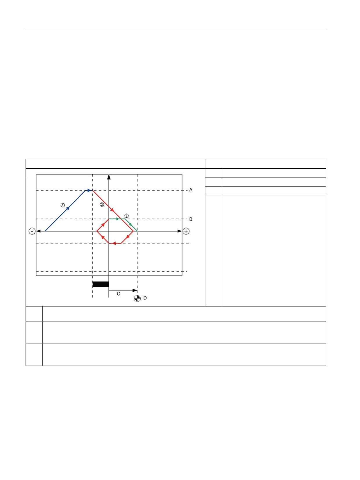
The following diagram shows an example of a characteristic curve for an active reference
point approach with the following configuration parameters:
● "Approach direction" = "Positive approach direction"
● "Reference point switch" = "Right (positive) side"
● Value of "home position offset" > 0
Table 10- 26 Velocity characteristics of MC homing
Operation
Notes
A
Approach velocity
B
Reduced velocity
C
Home position coordinate
D
Home position offset
Search phase (blue curve segment): When active homing starts, the axis accelerates to the configured "approach
①
velocity" and searches at this velocity for the reference point switch.
②
Reference point approach (red curve section): When the reference point switch is detected, the axis in this example
brakes and reverses, to be homed on the configured side of the reference point switch at the configured "reduced
velocity".
Travel to reference point position (green curve segment): After homing at the reference point switch, the axis travels
③
to the "Reference point coordinates" at the "reduced velocity". On reaching the "Reference point coordinates", the
axis is stopped at the position value that was specified in the Position input parameter of the MC_Home instruction".
306
Motion control is easy
10.7 Motion control instructions
Note
If the homing search does not function as you expected, check the inputs assigned to the
hardware limits or to the reference point. These inputs may have had their edge interrupts
disabled in device configuration.
Examine the configuration data for the axis technology object of concern to see which inputs
(if any) are assigned for "HW Low Limit Switch Input", "HW High Limit Switch Input", and
"Input reference point switch". Then open the Device configuration for the CPU and examine
each of the assigned inputs. Verify the "Enable rising edge detection" and "Enable falling
edge detection" are both selected. If these properties are not selected, delete the specified
inputs in the axis configuration and select them again.
10.7
Motion control instructions
10.7.1
MC instruction overview
The motion control instructions use an associated technology data block and the dedicated
PTO (pulse train outputs) of the CPU to control the motion on an axis.
● MC_Power (Page 308) enables and disables a motion control axis.
● MC_Reset (Page 311) resets all motion control errors. All motion control errors that can
be acknowledged are acknowledged.
● MC_Home (Page 312) establishes the relationship between the axis control program and
the axis mechanical positioning system.
● MC_Halt (Page 315) cancels all motion processes and causes the axis motion to stop.
The stop position is not defined.
● MC_MoveAbsolute (Page 317) starts motion to an absolute position. The job ends when
the target position is reached.
● MC_MoveRelative (Page 319) starts a positioning motion relative to the start position.
● MC_MoveVelocity (Page 321) causes the axis to travel with the specified speed.
● MC_MoveJog (Page 324) executes jog mode for testing and startup purposes.
● MC_CommandTable (Page 326) runs axis commands as a movement sequence.
● MC_ChangeDynamic (Page 328) changes Dynamics settings for the axis.
● MC_WriteParam (Page 330) writes a select number of parameters to change the
functionality of the axis from the user program.
● MC_ReadParam (Page 332) reads a select number of parameters that indicate the
current position, velocity, and so forth of the axis defined in the Axis input.
307
Motion control is easy
10.7 Motion control instructions
CPU firmware levels
If you have an S7-1200 CPU with V4.1 firmware, select the V5.0 version of each motion
instruction.
If you have an S7-1200 CPU with V4.0 or earlier firmware, select the applicable V4.0, V3.0,
V2.0, or V1.0 version of each motion instruction.
10.7.2
MC_Power (Release/block axis) instruction
Note
If the axis is switched off due to an error, it will be enabled again automatically after the error
has been eliminated and acknowledged. This requires that the Enable input parameter has
retained the value TRUE during this process.
Table 10- 27 MC_Power instruction
LAD / FBD
SCL
Description
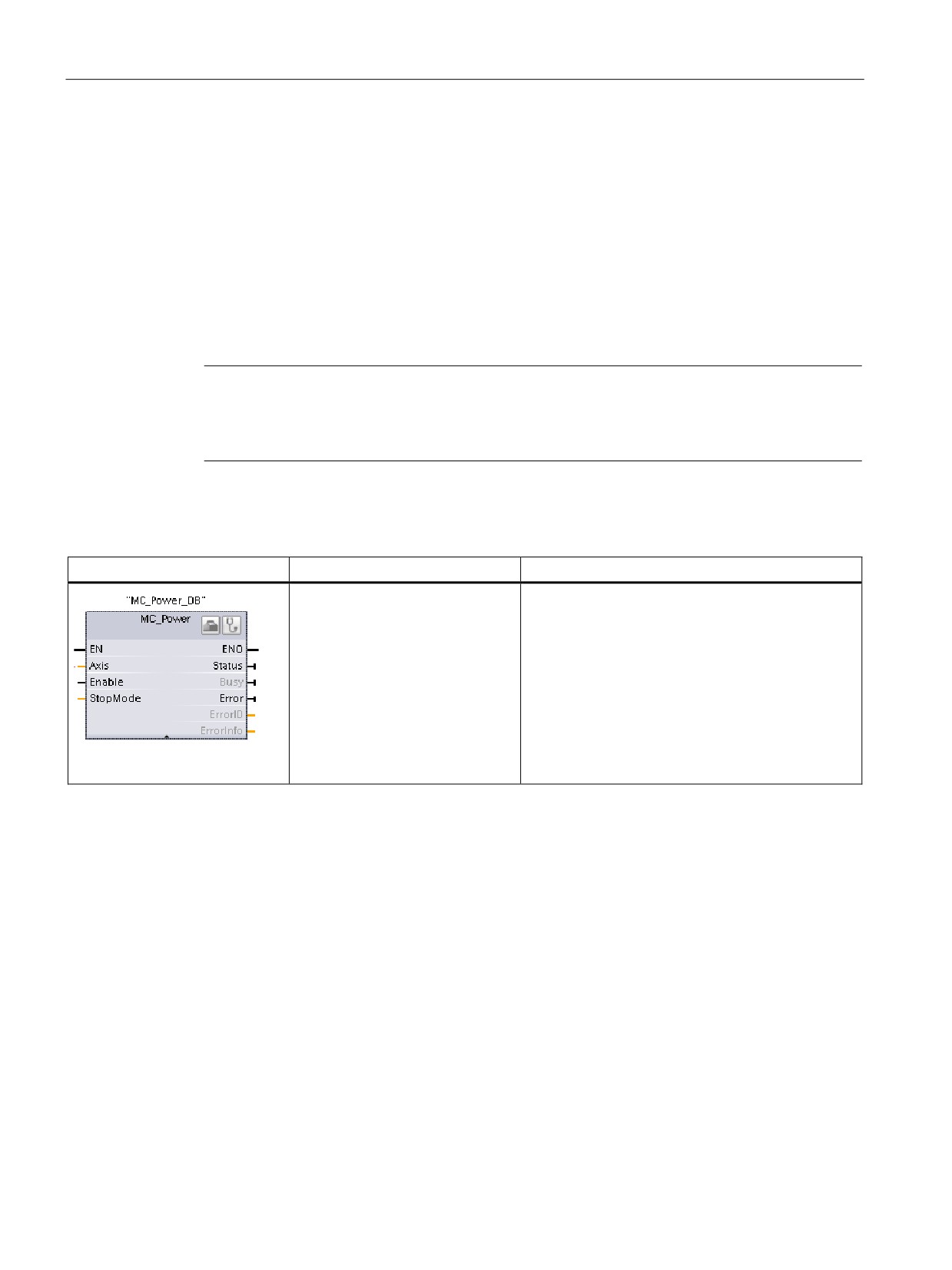
"MC_Power_DB"(
The MC_Power motion control instruction enables
Axis:=_multi_fb_in_,
or disables an axis. Before you can enable or disa-
Enable:=_bool_in_,
ble the axis, ensure the following conditions:
StopMode:=_int_in_,
• The technology object has been configured
Status=>_bool_out_,
correctly.
Busy=>_bool_out_,
• There is no pending enable-inhibiting error.
Error=>_bool_out_,
The execution of MC_Power cannot be aborted by
ErrorID=>_word_out_,
a motion control task. Disabling the axis (input
ErrorIn-
parameter Enable = FALSE) aborts all motion con-
fo=>_word_out_);
trol tasks for the associated technology object.
1
STEP 7 automatically creates the DB when you insert the instruction.
2
In the SCL example, "MC_Power_DB" is the name of the instance DB.
308

Motion control is easy
10.7 Motion control instructions
Table 10- 28 Parameters for the MC_Power instruction
Parameter and type
Data type
Description
Axis
IN
TO_Axis_1
Axis technology object
Enable
IN
Bool
• FALSE (default): All active tasks are aborted according to the pa-
rameterized "StopMode" and the axis is stopped.
• TRUE: Motion Control attempts to enable the axis.
StopMode
IN
Int
•
0: Emergency stop: If a request to disable the axis is pending, the
axis brakes at the configured emergency deceleration. The axis is
disabled after reaching standstill.
•
1: Immediate stop: If a request to disable the axis is pending, this
axis is disabled without deceleration. Pulse output is stopped imme-
diately.
•
2: Emergency stop with jerk control: If a request to disable the axis is
pending, the axis brakes at the configured emergency stop decelera-
tion. If the jerk control is activated, the configured jerk is taken into
account. The axis is disabled after reaching standstill.
Status
OUT
Bool
Status of axis enable:
• FALSE: The axis is disabled:
- The axis does not execute motion control tasks and does not ac-
cept any new tasks (exception: MC_Reset task).
- The axis is not homed.
- Upon disabling, the status does not change to FALSE until the
axis reaches a standstill.
• TRUE: The axis is enabled:
- The axis is ready to execute motion control tasks.
- Upon axis enabling, the status does not change to TRUE until
the signal "Drive ready" is pending. If the "Drive ready" drive in-
terface was not configured in the axis configuration, the status
changes to TRUE immediately.
Busy
OUT
Bool
FALSE: MC_Power is not active.
TRUE: MC_Power is active.
Error
OUT
Bool
FALSE: No error
TRUE: An error has occurred in motion control instruction "MC_Power"
or in the associated technology object. The cause of the error can be
found in parameters "ErrorID" and "ErrorInfo".
ErrorID
OUT
Word
Error ID for parameter "Error""
ErrorInfo
OUT
Word
Error info ID for parameter "ErrorID"
309
Motion control is easy
10.7 Motion control instructions
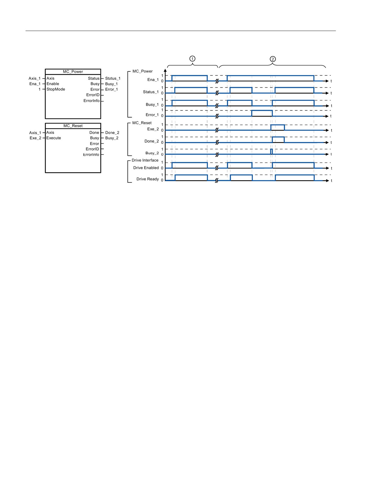
①
An axis is enabled and then disabled again. After the drive has signaled "Drive ready" back to the CPU, the suc-
cessful enable can be read out via "Status_1".
②
Following an axis enable, an error has occurred that caused the axis to be disabled. The error is eliminated and
acknowledged with "MC_Reset". The axis is then enabled again.
To enable an axis with configured drive interface, follow these steps:
1. Check the requirements indicated above.
2. Initialize input parameter "StopMode" with the desired value. Set input parameter
"Enable" to TRUE.
The enable output for "Drive enabled" changes to TRUE to enable the power to the drive.
The CPU waits for the "Drive ready" signal of the drive.
When the "Drive ready" signal is available at the configured ready input of the CPU, the
axis becomes enabled. Output parameter "Status" and technology object tag <Axis
name>.StatusBits.Enable indicates the value TRUE.
To enable an axis without configured drive interface, follow these steps:
1. Check the requirements indicated above.
2. Initialize input parameter "StopMode" with the desired value. Set input parameter
"Enable" to TRUE. The axis is enabled. Output parameter "Status" and technology object
tag <Axis name>.StatusBits.Enable indicate the value TRUE.
To disable an axis, follow these steps:
1. Bring the axis to a standstill.
You can identify when the axis is at a standstill in technology object tag <Axis
name>.StatusBits.StandStill.
2. Set input parameter "Enable" to FALSE after standstill is reached.
3. If output parameters "Busy" and "Status" and technology object tag <Axis
name>.StatusBits.Enable indicate the value FALSE, disabling of the axis is complete.
310
Motion control is easy
10.7 Motion control instructions
10.7.3
MC_Reset (Confirm error) instruction
Table 10- 29 MC_Reset instruction
LAD / FBD
SCL
Description
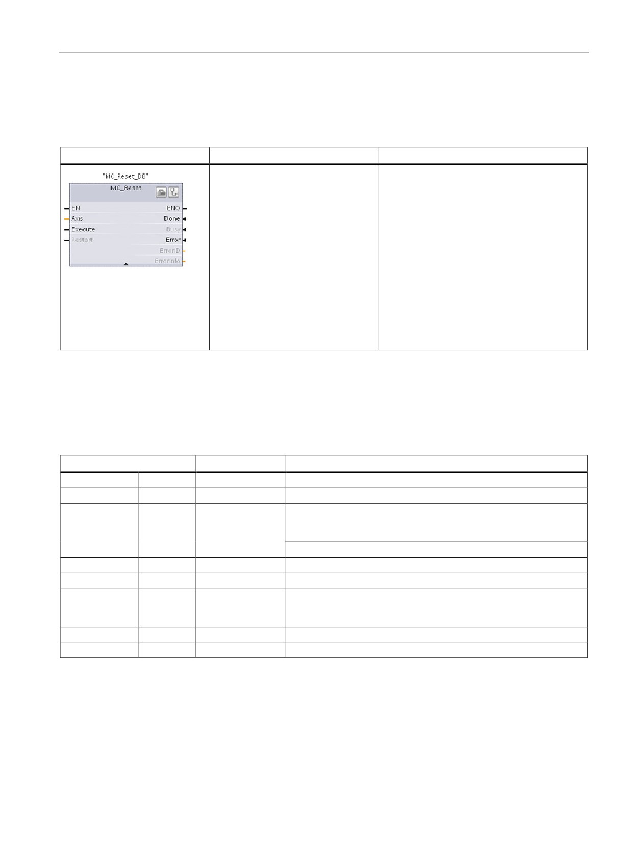
"MC_Reset_DB"(
Use the MC_Reset instruction to acknowledge
Axis:=_multi_fb_in_,
"Operating error with axis stop" and "Configura-
Execute:=_bool_in_,
tion error". The errors that require acknowl-
Restart:=_bool_in_,
edgement can be found in the "List of ErrorIDs
and ErrorInfos" under "Remedy".
Done=>_bool_out_,
Busy=>_bool_out_,
Before using the MC_Reset instruction, you
Error=>_bool_out_,
must have eliminated the cause of a pending
configuration error requiring acknowledgement
ErrorID=>_word_out_,
(for example, by changing an invalid accelera-
ErrorInfo=>_word_out_);
tion value in "Axis" technology object to a valid
value).
As of V3.0 and later, the Restart command
allows the axis configuration to be downloaded
to the work memory in the RUN operating
mode.
1
STEP 7 automatically creates the DB when you insert the instruction.
2
In the SCL example, "MC_Reset_DB" is the name of the instance DB.
The MC_Reset task cannot be aborted by any other motion control task. The new MC_Reset
task does not abort any other active motion control tasks.
Table 10- 30 Parameters of the MC_Reset instruction
Parameter and type
Data type
Description
Axis
IN
TO_Axis_1
Axis technology object
Execute
IN
Bool
Start of the task with a positive edge
Restart
IN
Bool
TRUE = Download the axis configuration from the load memory to the
work memory. The command can only be executed when the axis is
disabled.
FALSE = Acknowledges pending errors
Done
OUT
Bool
TRUE = Error has been acknowledged.
Busy
OUT
Bool
TRUE = The task is being executed.
Error
OUT
Bool
TRUE = An error has occurred during execution of the task. The
cause of the error can be found in parameters "ErrorID" and "ErrorIn-
fo".
ErrorID
OUTP
Word
Error ID for parameter "Error""
ErrorInfo
OUT
Word
Error info ID for parameter "ErrorID"
To acknowledge an error with MC_Reset, follow these steps:
1. Check the requirements indicated above.
2. Start the acknowledgement of the error with a rising edge at the Execute input parameter.
3. The error has been acknowledged when Done equals TRUE and the technology object
tag <Axis name>.StatusBits.Error equals FALSE.
311
Motion control is easy
10.7 Motion control instructions
10.7.4
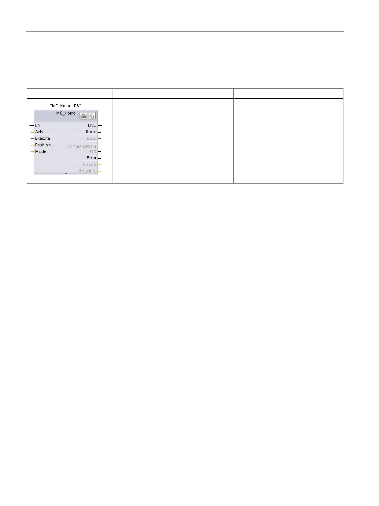
MC_Home (Home axis) instruction
Table 10- 31 MC_Home instruction
LAD / FBD
SCL
Description
"MC_Home_DB"(
Use the MC_Home instruction to match
Axis:=_multi_fb_in_,
the axis coordinates to the real, physical
Execute:=_bool_in_,
drive position. Homing is required for
Position:=_real_in_,
absolute positioning of the axis:
Mode:=_int_in_,
In order to use the MC_Home instruction,
Done=>_bool_out_,
the axis must first be enabled.
Busy=>_bool_out_,
CommandAborted=>_bool_out_,
Error=>_bool_out_,
ErrorID=>_word_out_,
ErrorInfo=>_word_out_);
1
STEP 7 automatically creates the DB when you insert the instruction.
2
In the SCL example, "MC_Home_DB" is the name of the instance DB.
The following types of homing are available:
● Direct homing absolute (Mode = 0): The current axis position is set to the value of
parameter "Position".
● Direct homing relative (Mode = 1): The current axis position is offset by the value of
parameter "Position".
● Passive homing (Mode = 2): During passive homing, the MC_Home instruction does not
carry out any homing motion. The traversing motion required for this step must be
implemented by the user via other motion control instructions. When the reference point
switch is detected, the axis is homed.
● Active homing (Mode = 3): The homing procedure is executed automatically.
312

Motion control is easy
10.7 Motion control instructions
Table 10- 32 Parameters for the MC_Home instruction
Parameter and type
Data type
Description
Axis
IN
TO_Axis_PTO
Axis technology object
Execute
IN
Bool
Start of the task with a positive edge
Position
IN
Real
• Mode = 0, 2, and 3 (Absolute position of axis after comple-
tion of the homing operation)
• Mode = 1 (Correction value for the current axis position)
Limit values: -1.0e12 ≤ Position ≤ 1.0e12
Mode
IN
Int
Homing mode
•
0: Direct homing absolute
New axis position is the position value of parameter "Posi-
tion".
•
1: Direct homing relative
New axis position is the current axis position + position
value of parameter "Position".
•
2: Passive homing
Homing according to the axis configuration. Following
homing, the value of parameter "Position" is set as the
new axis position.
•
3: Active homing
Reference point approach in accordance with the axis
configuration. Following homing, the value of parameter
"Position" is set as the new axis position.
Done
OUT
Bool
TRUE = Task completed
Busy
OUT
Bool
TRUE = The task is being executed.
CommandAborted
OUT
Bool
TRUE = During execution the task was aborted by another
task.
Error
OUT
Bool
TRUE = An error has occurred during execution of the task.
The cause of the error can be found in parameters "ErrorID"
and "ErrorInfo".
ErrorID
OUT
Word
Error ID for parameter "Error""
ErrorInfo
OUT
Word
Error info ID for parameter "ErrorID"
Note
Axis homing is lost under the following conditions
• Disabling of axis by the MC_Power instruction
• Switchover between automatic control and manual control
• Upon start of active homing (After successful completion of the homing operation, axis
homing is available again.)
• After power-cycling the CPU
• After CPU restart (RUN-to-STOP or STOP-to-RUN)
313

Motion control is easy
10.7 Motion control instructions
To home the axis, follow these steps:
1. Check the requirements indicated above.
2. Initialize the necessary input parameters with values, and start the homing operation with
a rising edge at input parameter "Execute".
3. If output parameter "Done" and technology object tag <Axis
name>.StatusBits.HomingDone indicate the value TRUE, homing is complete.
Table 10- 33
Override response
Mode
Description
0 or 1
The MC_Home task cannot be aborted by any other motion control task. The new MC_Home task does not
abort any active motion control tasks. Position-related motion tasks are resumed after homing according to
the new homing position (value at the Position input parameter).
2
The MC_Home task can be aborted by the following motion control tasks:
MC_Home task Mode = 2, 3: The new MC_Home task aborts the following active motion control task.
MC_Home task Mode = 2: Position-related motion tasks are resumed after homing according to the new
homing position (value at the Position input parameter).
3
The MC_Home task can be aborted by the following
The new MC_Home task aborts the following active
motion control tasks:
motion control tasks:
• MC_Home Mode = 3
• MC_Home Mode = 2, 3
• MC_Halt
• MC_Halt
• MC_MoveAbsolute
• MC_MoveAbsolute
• MC_MoveRelative
• MC_MoveRelative
• MC_MoveVelocity
• MC_MoveVelocity
• MC_MoveJog
• MC_MoveJog
314
Motion control is easy
10.7 Motion control instructions
10.7.5
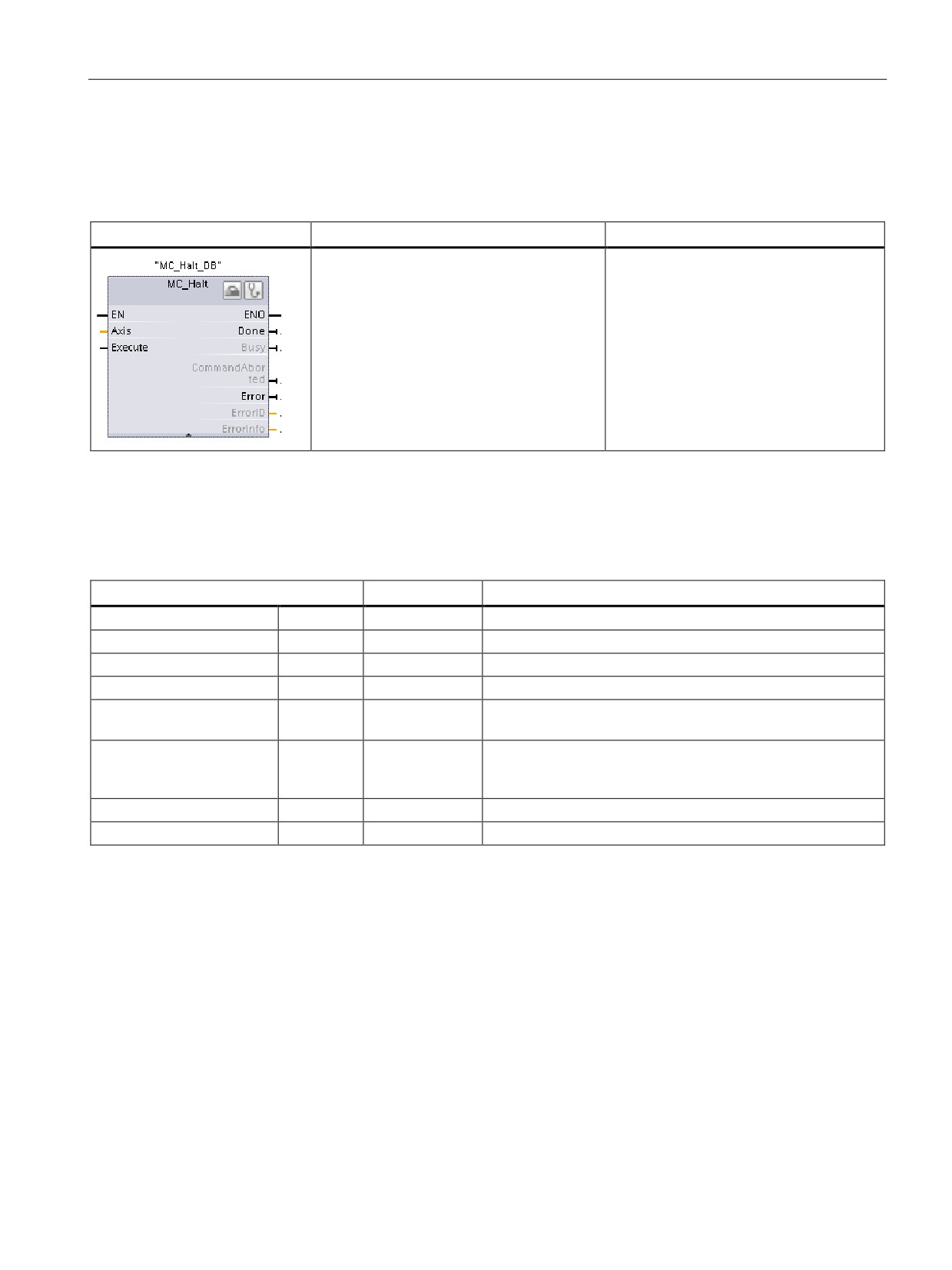
MC_Halt (Pause axis) instruction
Table 10- 34 MC_Halt instruction
LAD / FBD
SCL
Description
"MC_Halt_DB"(
Use the MC_Halt instruction to stop all
Axis:=_multi_fb_in_,
motion and to bring the axis to a stand-
Execute:=_bool_in_,
still. The stand-still position is not defined.
Done=>_bool_out_,
In order to use the MC_Halt instruction,
Busy=>_bool_out_,
the axis must first be enabled.
CommandAborted=>_bool_out_,
Error=>_bool_out_,
ErrorID=>_word_out_,
ErrorInfo=>_word_out_);
1
STEP 7 automatically creates the DB when you insert the instruction.
2
In the SCL example, "MC_Halt_DB" is the name of the instance DB.
Table 10- 35 Parameters for the MC_Halt instruction
Parameter and type
Data type
Description
Axis
IN
TO_Axis_1
Axis technology object
Execute
IN
Bool
Start of the task with a positive edge
Done
OUT
Bool
TRUE = Zero velocity reached
Busy
OUT
Bool
TRUE = The task is being executed.
CommandAborted
OUT
Bool
TRUE = During execution the task was aborted by another
task.
Error
OUT
Bool
TRUE = An error has occurred during execution of the task.
The cause of the error can be found in parameters "ErrorID"
and "ErrorInfo".
ErrorID
OUT
Word
Error ID for parameter "Error"
ErrorInfo
OUT
Word
Error info ID for parameter "ErrorID"
315
Motion control is easy
10.7 Motion control instructions
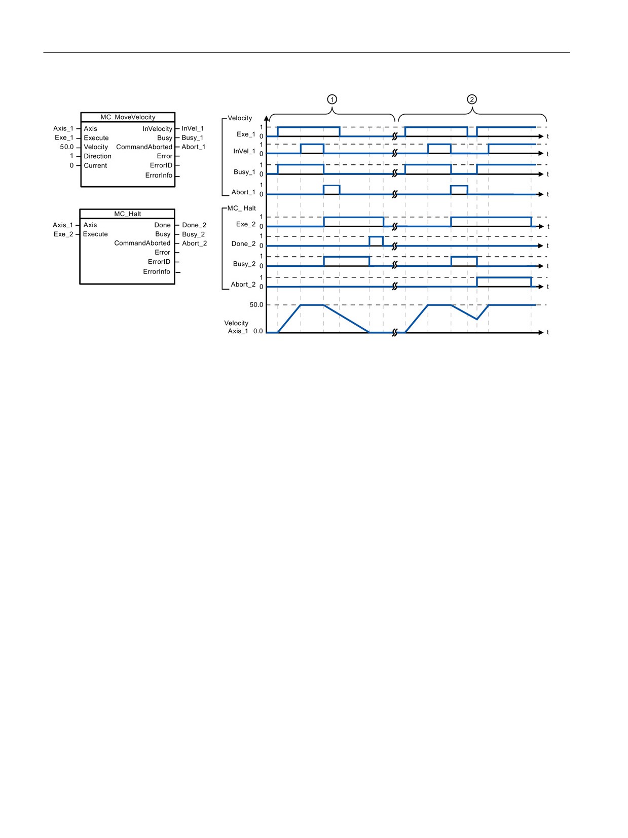
The following values were configured in the "Dynamics > General" configuration window: Acceleration = 10.0 and Decelera-
tion = 5.0
① The axis is braked by an MC_Halt task until it comes to a standstill. The axis standstill is signaled via "Done_2".
② While an MC_Halt task is braking the axis, this task is aborted by another motion task. The abort is signaled via
"Abort_2".
Override response
The MC_Halt task can be aborted by the
The new MC_Halt task aborts the following
following motion control tasks:
active motion control tasks:
• MC_Home Mode = 3
• MC_Home Mode = 3
• MC_Halt
• MC_Halt
• MC_MoveAbsolute
• MC_MoveAbsolute
• MC_MoveRelative
• MC_MoveRelative
• MC_MoveVelocity
• MC_MoveVelocity
• MC_MoveJog
• MC_MoveJog
316
Motion control is easy
10.7 Motion control instructions
10.7.6
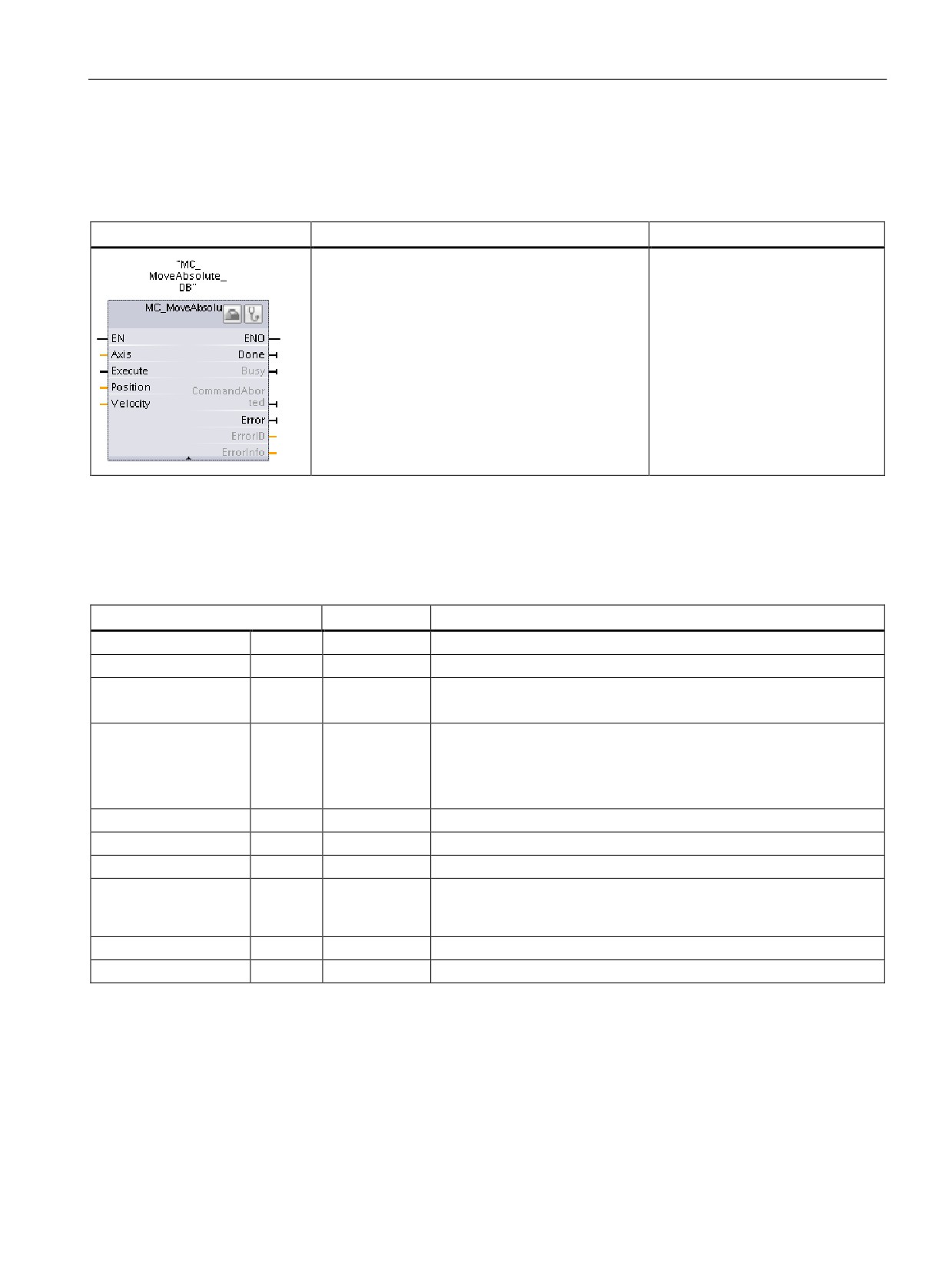
MC_MoveAbsolute (Position axis absolutely) instruction
Table 10- 36 MC_MoveAbsolute instruction
LAD / FBD
SCL
Description
"MC_MoveAbsolute_DB"(
Use the MC_MoveAbsolute in-
Axis:=_multi_fb_in_,
struction to start a positioning
Execute:=_bool_in_,
motion of the axis to an absolute
Position:=_real_in_,
position.
Velocity:=_real_in_,
In order to use the
Done=>_bool_out_,
MC_MoveAbsolute instruction, the
Busy=>_bool_out_,
axis must first be enabled and also
must be homed.
CommandAborted=>_bool_out_,
Error=>_bool_out_,
ErrorID=>_word_out_,
ErrorInfo=>_word_out_);
1
STEP 7 automatically creates the DB when you insert the instruction.
2
In the SCL example, "MC_MoveAbsolute_DB" is the name of the instance DB.
Table 10- 37 Parameters for the MC_MoveAbsolute instruction
Parameter and type
Data type
Description
Axis
IN
TO_Axis_1
Axis technology object
Execute
IN
Bool
Start of the task with a positive edge (Default value: False)
Position
IN
Real
Absolute target position (Default value: 0.0)
Limit values: -1.0e12 ≤ Position ≤ 1.0e12
Velocity
IN
Real
Velocity of axis (Default value: 10.0)
This velocity is not always reached because of the configured accel-
eration and deceleration and the target position to be approached.
Limit values: Start/stop velocity ≤ Velocity ≤ maximum velocity
Done
OUT
Bool
TRUE = Absolute target position reached
Busy
OUT
Bool
TRUE = The task is being executed.
CommandAborted
OUT
Bool
TRUE = During execution the task was aborted by another task.
Error
OUT
Bool
TRUE = An error has occurred during execution of the task. The
cause of the error can be found in parameters "ErrorID" and "ErrorIn-
fo".
ErrorID
OUT
Word
Error ID for parameter "Error" (Default value: 0000)
ErrorInfo
OUT
Word
Error info ID for parameter "ErrorID" (Default value: 0000)
317
Motion control is easy
10.7 Motion control instructions
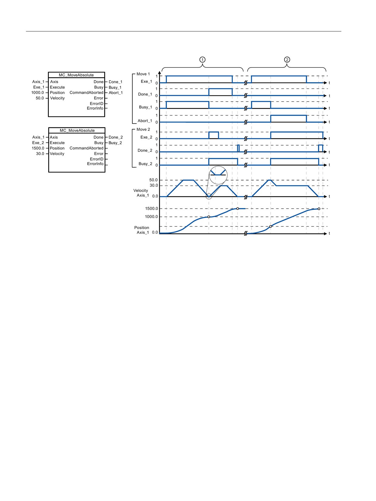
The following values were configured in the "Dynamics > General" configuration window: Acceleration = 10.0 and Decelera-
tion = 10.0
① An axis is moved to absolute position 1000.0 with a MC_MoveAbsolute task. When the axis reaches the target
position, this is signaled via "Done_1". When "Done_1" = TRUE, another MC_MoveAbsolute task, with target posi-
tion 1500.0, is started. Because of the response times (e.g., cycle time of user program, etc.), the axis comes to a
standstill briefly (see zoomed-in detail). When the axis reaches the new target position, this is signaled via
"Done_2".
② An active MC_MoveAbsolute task is aborted by another MC_MoveAbsolute task. The abort is signaled via
"Abort_1". The axis is then moved at the new velocity to the new target position 1500.0. When the new target posi-
tion is reached, this is signaled via "Done_2".
Override response
The MC_MoveAbsolute task can be abort-
The new MC_MoveAbsolute task aborts
ed by the following motion control tasks:
the following active motion control tasks:
• MC_Home Mode = 3
• MC_Home Mode = 3
• MC_Halt
• MC_Halt
• MC_MoveAbsolute
• MC_MoveAbsolute
• MC_MoveRelative
• MC_MoveRelative
• MC_MoveVelocity
• MC_MoveVelocity
• MC_MoveJog
• MC_MoveJog
318
Motion control is easy
10.7 Motion control instructions
10.7.7
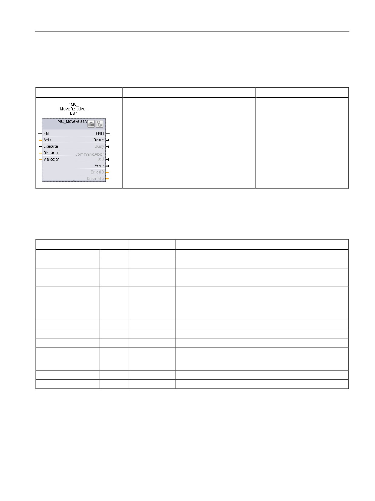
MC_MoveRelative (Position axis relatively) instruction
Table 10- 38 MC_MoveRelative instruction
LAD / FBD
SCL
Description
"MC_MoveRelative_DB"(
Use the MC_MoveRelative instruc-
Axis:=_multi_fb_in_,
tion to start a positioning motion
Execute:=_bool_in_,
relative to the start position.
Distance:=_real_in_,
In order to use the
Velocity:=_real_in_,
MC_MoveRelative instruction, the
Done=>_bool_out_,
axis must first be enabled.
Busy=>_bool_out_,
CommandAborted=>_bool_out_,
Error=>_bool_out_,
ErrorID=>_word_out_,
ErrorInfo=>_word_out_);
1
STEP 7 automatically creates the DB when you insert the instruction.
2
In the SCL example, "MC_MoveRelative_DB " is the name of the instance DB.
Table 10- 39 Parameters for the MC_MoveRelative instruction
Parameter and type
Data type
Description
Axis
IN
TO_Axis_1
Axis technology object
Execute
IN
Bool
Start of the task with a positive edge (Default value: False)
Distance
IN
Real
Travel distance for the positioning operation (Default value: 0.0)
Limit values: -1.0e12 ≤ Distance ≤ 1.0e12
Velocity
IN
Real
Velocity of axis (Default value: 10.0)
This velocity is not always reached on account of the configured
acceleration and deceleration and the distance to be traveled.
Limit values: Start/stop velocity ≤ Velocity ≤ maximum velocity
Done
OUT
Bool
TRUE = Target position reached
Busy
OUT
Bool
TRUE = The task is being executed.
CommandAborted
OUT
Bool
TRUE = During execution the task was aborted by another task.
Error
OUT
Bool
TRUE = An error has occurred during execution of the task. The
cause of the error can be found in parameters "ErrorID" and "Error-
Info".
ErrorID
OUT
Word
Error ID for parameter "Error" (Default value: 0000)
ErrorInfo
OUT
Word
Error info ID for parameter "ErrorID" (Default value: 0000)
319
Motion control is easy
10.7 Motion control instructions
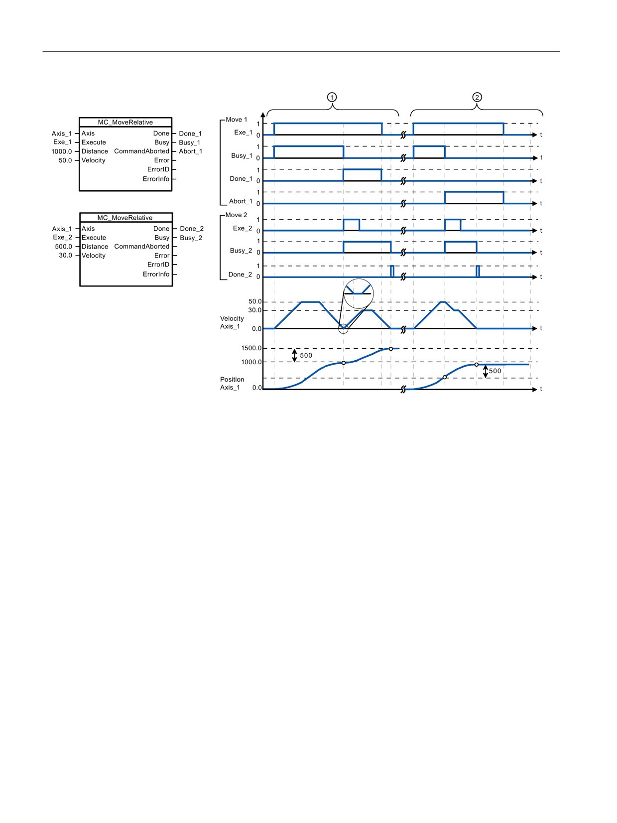
The following values were configured in the "Dynamics > General" configuration window: Acceleration = 10.0 and Decelera-
tion = 10.0
① The axis is moved by an MC_MoveRelative task by the distance ("Distance") 1000.0. When the axis reaches the
target position, this is signaled via "Done_1". When "Done_1" = TRUE, another MC_MoveRelative task, with travel
distance 500.0, is started. Because of the response times (for example, cycle time of user program), the axis
comes to a standstill briefly (see zoomed-in detail). When the axis reaches the new target position, this is signaled
via "Done_2".
② An active MC_MoveRelative task is aborted by another MC_MoveRelative task. The abort is signaled via
"Abort_1". The axis is then moved at the new velocity by the new distance ("Distance") 500.0. When the new target
position is reached, this is signaled via "Done_2".
Override response
The MC_MoveRelative task can be aborted
The new MC_MoveRelative task aborts the
by the following motion control tasks:
following active motion control tasks:
• MC_Home Mode = 3
• MC_Home Mode = 3
• MC_Halt
• MC_Halt
• MC_MoveAbsolute
• MC_MoveAbsolute
• MC_MoveRelative
• MC_MoveRelative
• MC_MoveVelocity
• MC_MoveVelocity
• MC_MoveJog
• MC_MoveJog
320
Motion control is easy
10.7 Motion control instructions
10.7.8
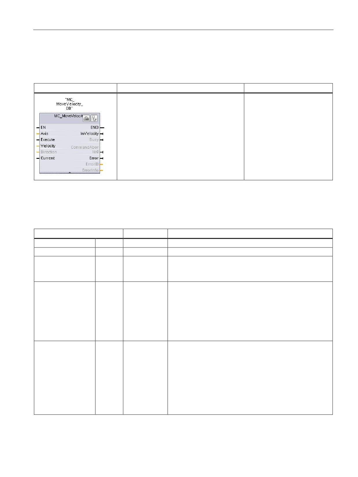
MC_MoveVelocity (Move axis at predefined velocity) instruction
Table 10- 40 MC_MoveVelocity instruction
LAD / FBD
SCL
Description
"MC_MoveVelocity_DB"(
Use the MC_MoveVelocity instruc-
Axis:=_multi_fb_in_,
tion to move the axis constantly at
Execute:=_bool_in_,
the specified velocity.
Velocity:=_real_in_,
In order to use the
Direction:=_int_in_,
MC_MoveVelocity instruction, the
Current:=_bool_in_,
axis must first be enabled.
InVelocity=>_bool_out_,
Busy=>_bool_out_,
CommandAborted=>_bool_out_,
Error=>_bool_out_,
ErrorID=>_word_out_,
ErrorInfo=>_word_out_);
1
STEP 7 automatically creates the DB when you insert the instruction.
2
In the SCL example, "MC_MoveVelocity_DB " is the name of the instance DB.
Table 10- 41 Parameters for the MC_MoveVelocity instruction
Parameter and type
Data type
Description
Axis
IN
TO_Axis_1
Axis technology object
Execute
IN
Bool
Start of the task with a positive edge (Default value: False)
Velocity
IN
Real
Velocity specification for axis motion (Default value: 10.0)
Limit values: Start/stop velocity ≤ |Velocity| ≤ maximum velocity
(Velocity = 0.0 is allowed)
Direction
IN
Int
Direction specification:
•
0: Direction of rotation corresponds to the sign of the value in
parameter "Velocity" (Default value)
•
1: Positive direction of rotation (The sign of the value in param-
eter "Velocity" is ignored.)
•
2: Negative direction of rotation (The sign of the value in pa-
rameter "Velocity" is ignored.)
Current
IN
Bool
Maintain current velocity:
• FALSE: "Maintain current velocity" is deactivated. The values
of parameters "Velocity" and "Direction" are used. (Default val-
ue)
• TRUE: "Maintain current velocity" is activated. The values in
parameters "Velocity" and "Direction" are not taken into ac-
count.
When the axis resumes motion at the current velocity, the "In-
Velocity" parameter returns the value TRUE.
321
Motion control is easy
10.7 Motion control instructions
Parameter and type
Data type
Description
InVelocity
OUT
Bool
TRUE:
• If "Current" = FALSE: The velocity specified in parameter "Ve-
locity" was reached.
• If "Current" = TRUE: The axis travels at the current velocity at
the start time.
Busy
OUT
Bool
TRUE = The task is being executed.
CommandAborted
OUT
Bool
TRUE = During execution the task was aborted by another task.
Error
OUT
Bool
TRUE = An error has occurred during execution of the task. The
cause of the error can be found in parameters "ErrorID" and "Error-
Info".
ErrorID
OUT
Word
Error ID for parameter "Error" (Default value: 0000)
ErrorInfo
OUT
Word
Error info ID for parameter "ErrorID" (Default value: 0000)
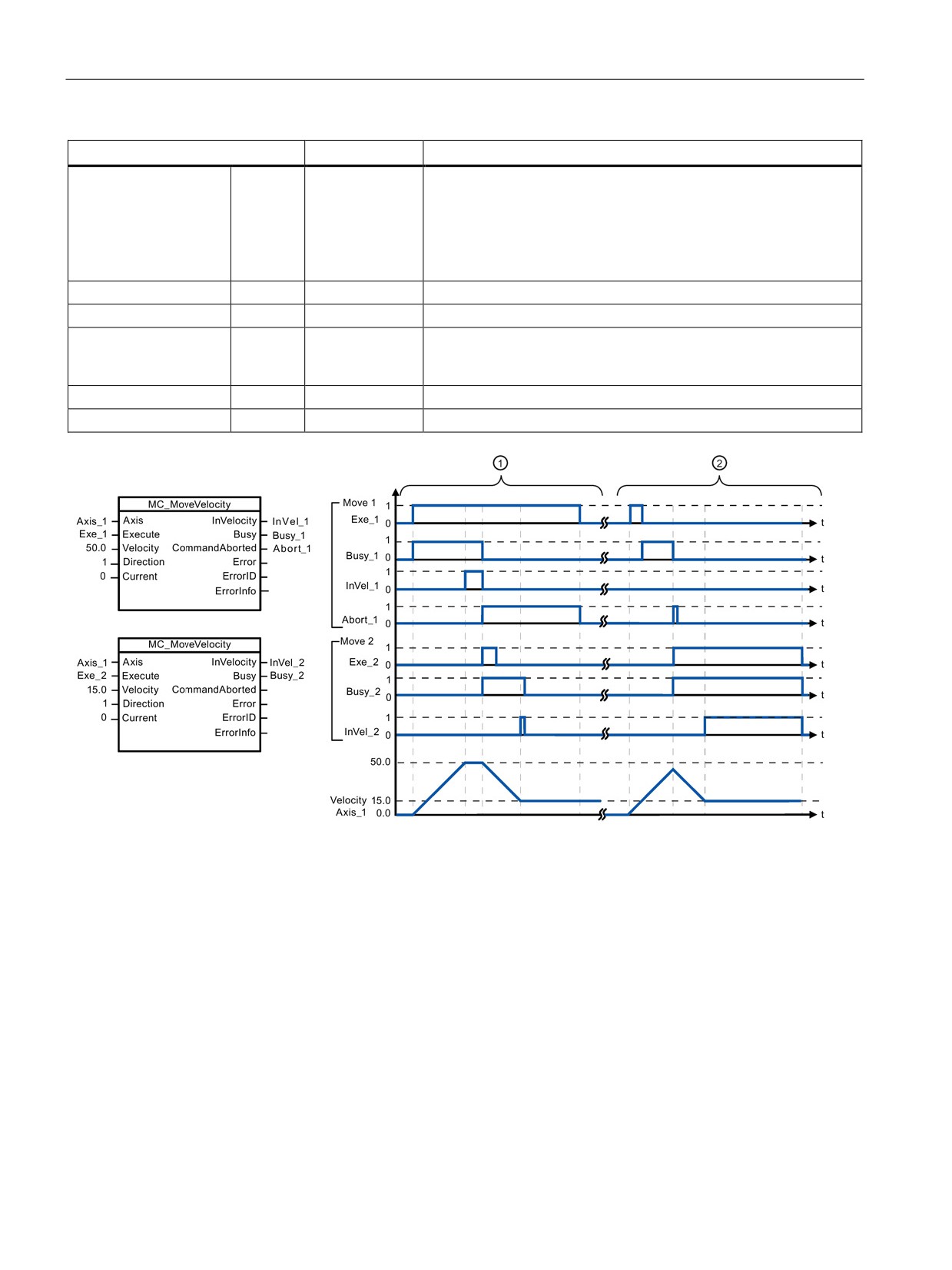
The following values were configured in the "Dynamics > General" configuration window: Acceleration = 10.0 and Decelera-
tion = 10.0
① An active MC_MoveVelocity task signals via "InVel_1" that its target velocity has been reached. It is then aborted
by another MC_MoveVelocity task. The abort is signaled via "Abort_1". When the new target velocity 15.0 is
reached, this is signaled via "InVel_2". The axis then continues moving at the new constant velocity.
② An active MC_MoveVelocity task is aborted by another MC_MoveVelocity task prior to reaching its target velocity.
The abort is signaled via "Abort_1". When the new target velocity 15.0 is reached, this is signaled via "InVel_2".
The axis then continues moving at the new constant velocity.
322
Motion control is easy
10.7 Motion control instructions
Override response
The MC_MoveVelocity task can be aborted
The new MC_MoveVelocity task aborts the
by the following motion control tasks:
following active motion control tasks:
• MC_Home Mode = 3
• MC_Home Mode = 3
• MC_Halt
• MC_Halt
• MC_MoveAbsolute
• MC_MoveAbsolute
• MC_MoveRelative
• MC_MoveRelative
• MC_MoveVelocity
• MC_MoveVelocity
• MC_MoveJog
• MC_MoveJog
Note
Behavior with zero set velocity (Velocity = 0.0)
An MC_MoveVelocity task with "Velocity" = 0.0 (such as an MC_Halt task) aborts active
motion tasks and stops the axis with the configured deceleration. When the axis comes to a
standstill, output parameter "InVelocity" indicates TRUE for at least one program cycle.
"Busy" indicates the value TRUE during the deceleration operation and changes to FALSE
together with "InVelocity". If parameter "Execute" = TRUE is set, "InVelocity" and "Busy" are
latched.
When the MC_MoveVelocity task is started, status bit "SpeedCommand" is set in the
technology object. Status bit "ConstantVelocity" is set upon axis standstill. Both bits are
adapted to the new situation when a new motion task is started.
323
Motion control is easy
10.7 Motion control instructions
10.7.9
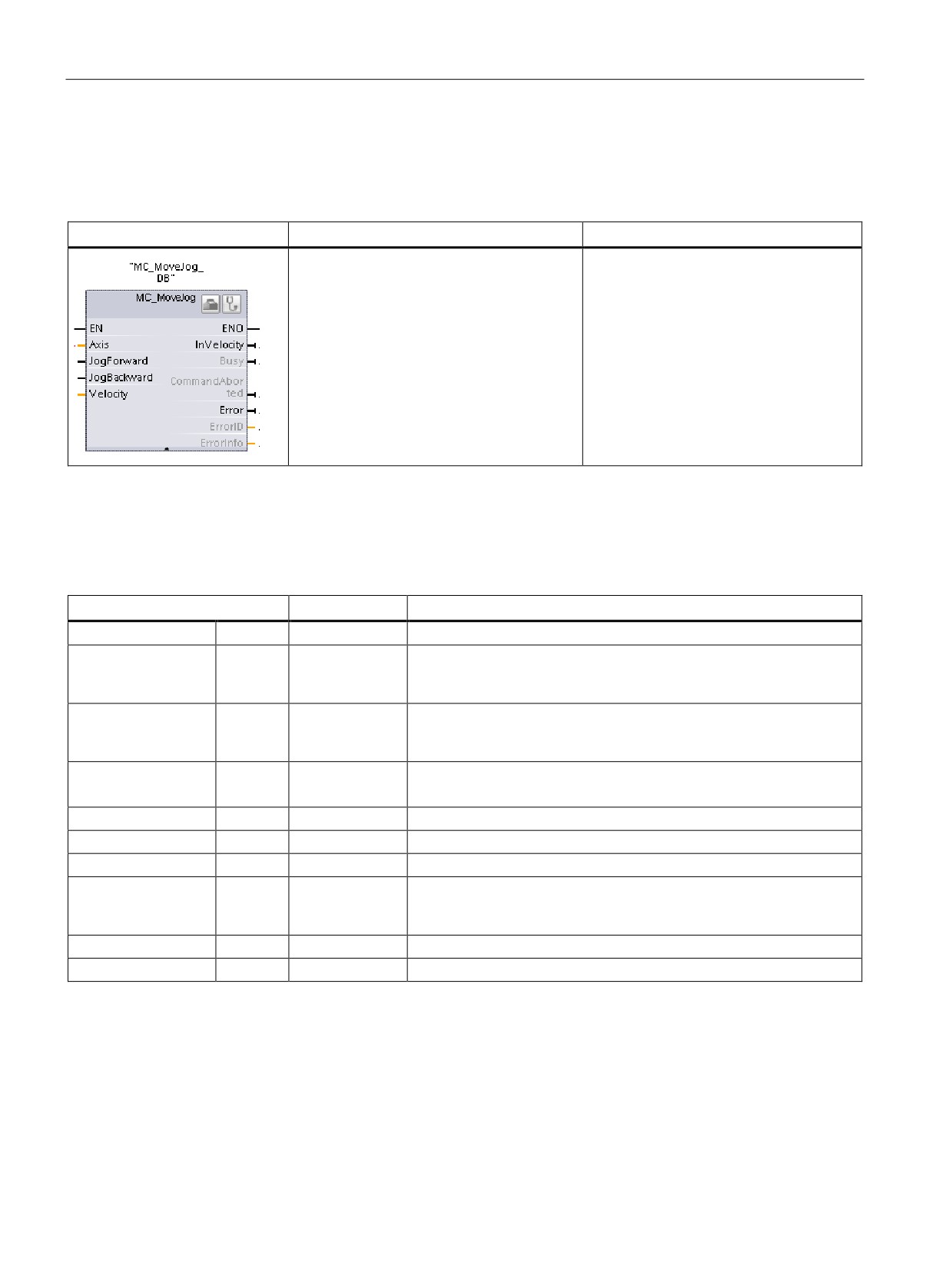
MC_MoveJog (Move axis in jog mode) instruction
Table 10- 42 MC_MoveJog instruction
LAD / FBD
SCL
Description
"MC_MoveJog_DB"(
Use the MC_MoveJog instruction to move
Axis:=_multi_fb_in_,
the axis constantly at the specified veloci-
JogForward:=_bool_in_,
ty in jog mode. This instruction is typically
JogBackward:=_bool_in_,
used for testing and commissioning pur-
poses.
Velocity:=_real_in_,
InVelocity=>_bool_out_,
In order to use the MC_MoveJog instruc-
Busy=>_bool_out_,
tion, the axis must first be enabled.
CommandAborted=>_bool_out_,
Error=>_bool_out_,
ErrorID=>_word_out_,
ErrorInfo=>_word_out_);
1
STEP 7 automatically creates the DB when you insert the instruction.
2
In the SCL example, "MC_MoveJog_DB " is the name of the instance DB.
Table 10- 43 Parameters for the MC_MoveJog instruction
Parameter and type
Data type
Description
Axis
IN
TO_Axis_1
Axis technology object
JogForward1
IN
Bool
As long as the parameter is TRUE, the axis moves in the positive
direction at the velocity specified in parameter "Velocity". The sign of
the value in parameter "Velocity" is ignored. (Default value: False)
JogBackward1
IN
Bool
As long as the parameter is TRUE, the axis moves in the negative
direction at the velocity specified in parameter "Velocity". The sign of
the value in parameter "Velocity" is ignored. (Default value: False)
Velocity
IN
Real
Preset velocity for jog mode (Default value: 10.0)
Limit values: Start/stop velocity ≤ |Velocity| ≤ maximum velocity
InVelocity
OUT
Bool
TRUE = The velocity specified in parameter "Velocity" was reached.
Busy
OUT
Bool
TRUE = The task is being executed.
CommandAborted
OUT
Bool
TRUE = During execution the task was aborted by another task.
Error
OUT
Bool
TRUE = An error has occurred during execution of the task. The
cause of the error can be found in parameters "ErrorID" and "ErrorIn-
fo".
ErrorID
OUT
Word
Error ID for parameter "Error" (Default value: 0000)
ErrorInfo
OUT
Word
Error info ID for parameter "ErrorID" (Default value: 0000)
1
If both the JogForward and JogBackward parameters are simultaneously TRUE, the axis stops with the configured
deceleration. An error is indicated in parameters "Error", "ErrorID", and "ErrorInfo".
324
Motion control is easy
10.7 Motion control instructions
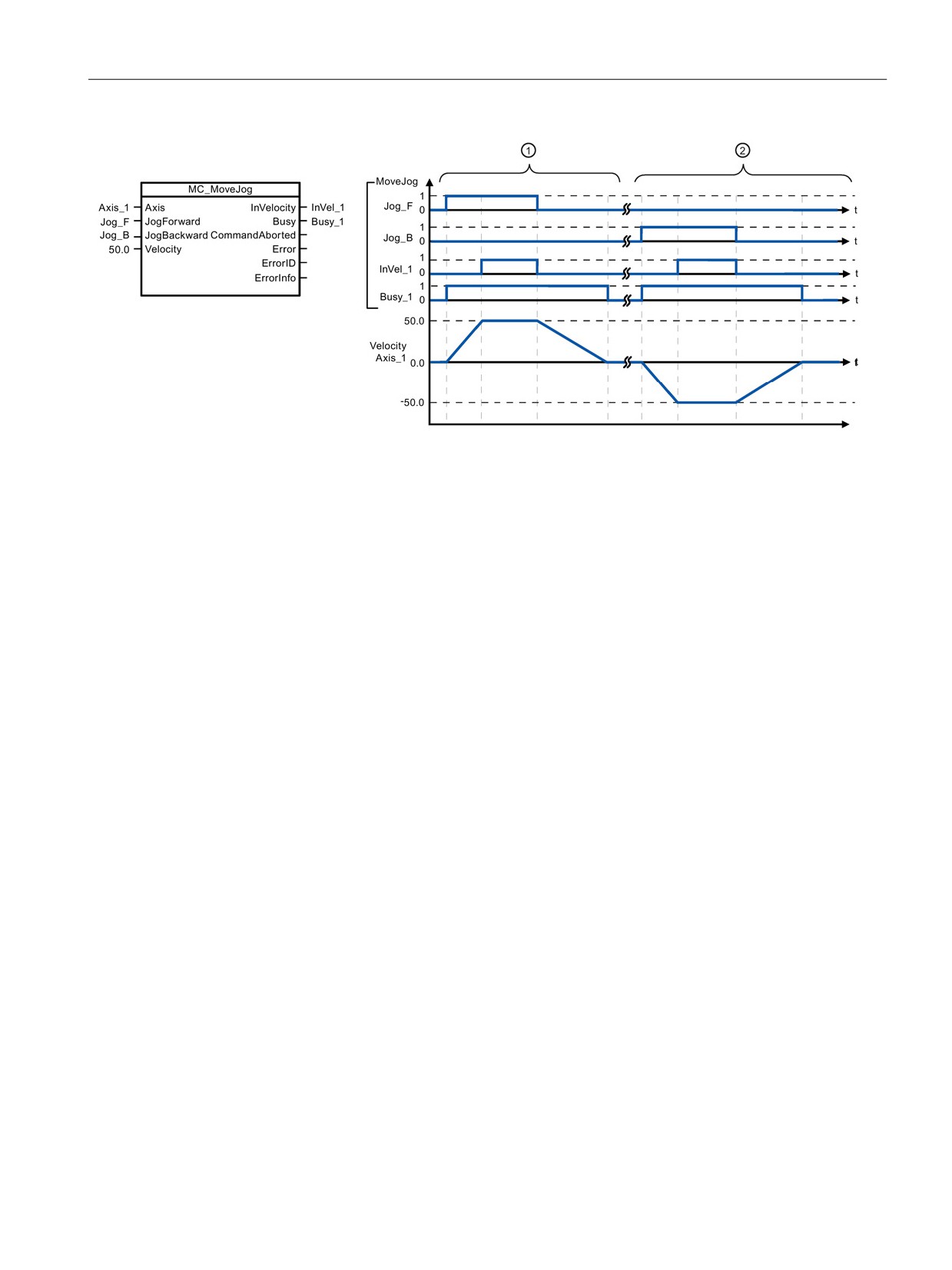
The following values were configured in the "Dynamics > General" configuration window: Acceleration = 10.0 and Decelera-
tion = 5.0
① The axis is moved in the positive direction in jog mode via "Jog_F". When the target velocity 50.0 is reached, this is
signaled via "InVelo_1". The axis brakes to a standstill again after Jog_F is reset.
② The axis is moved in the negative direction in jog mode via "Jog_B". When the target velocity 50.0 is reached, this
is signaled via "InVelo_1". The axis brakes to a standstill again after Jog_B is reset.
Override response
The MC_MoveJog task can be aborted by
The new MC_MoveJog task aborts the
the following motion control tasks:
following active motion control tasks:
• MC_Home Mode = 3
• MC_Home Mode = 3
• MC_Halt
• MC_Halt
• MC_MoveAbsolute
• MC_MoveAbsolute
• MC_MoveRelative
• MC_MoveRelative
• MC_MoveVelocity
• MC_MoveVelocity
• MC_MoveJog
• MC_MoveJog
325
Motion control is easy
10.7 Motion control instructions
10.7.10
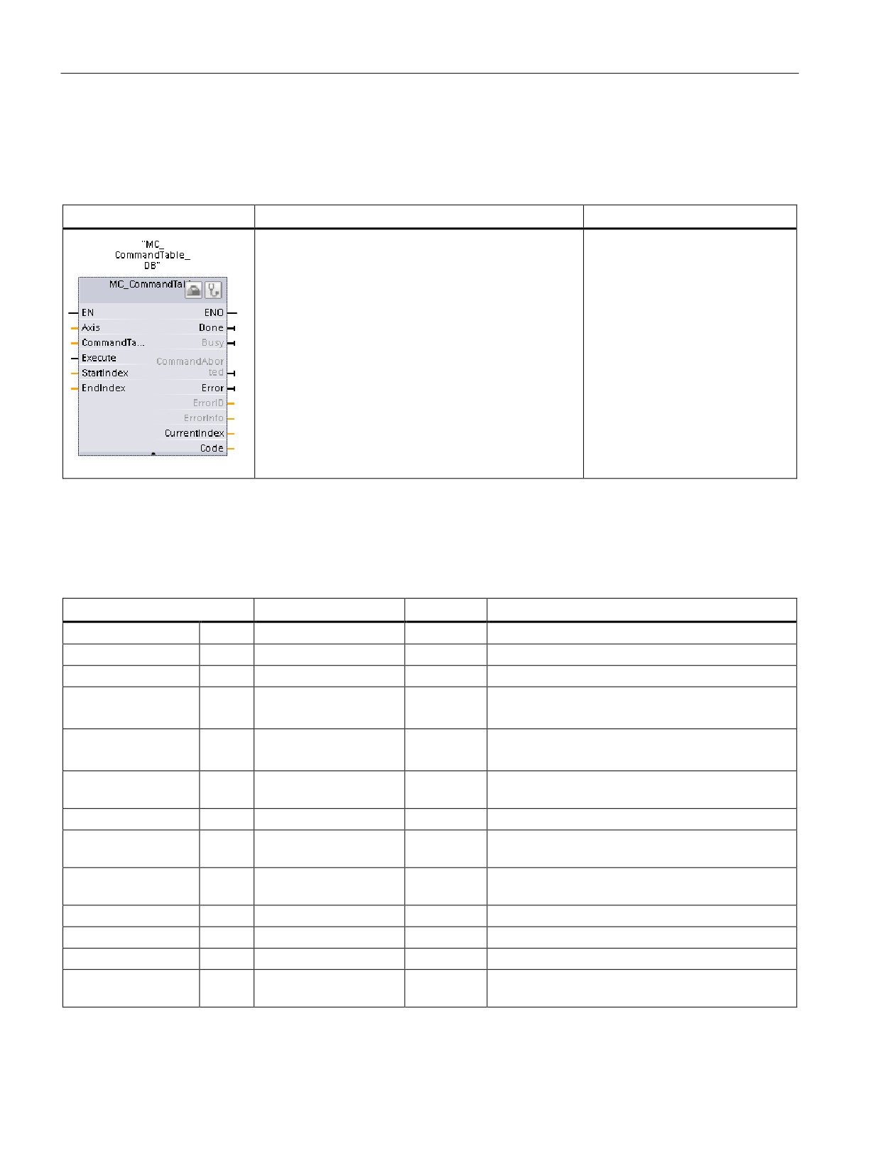
MC_CommandTable (Run axis commans as movement sequence) instruction
Table 10- 44 MC_CommandTable instruction
LAD / FBD
SCL
Description
"MC_CommandTable_DB"(
Executes a series of individual
Axis:=_multi_fb_in_,
motions for a motor control axis
CommandTable:=_multi_fb_in_,
that can combine into a move-
Execute:=_bool_in_,
ment sequence.
StartIndex:=_uint_in_,
Individual motions are configured
EndIndex:=_uint_in_,
in a technology object command
Done=>_bool_out_,
table for pulse train output
(TO_CommandTable_PTO).
Busy=>_bool_out_,
CommandAborted=>_bool_out_,
Error=>_bool_out_,
ErrorID=>_word_out_,
ErrorInfo=>_word_out_,
CurrentIndex=>_uint_out_,
Code=>_word_out_);
1
STEP 7 automatically creates the DB when you insert the instruction.
2
In the SCL example, "MC_CommandTable_DB " is the name of the instance DB.
Table 10- 45 Parameters for the MC_CommandTable instruction
Parameter and type
Data type
Initial value
Description
Axis
IN
TO_Axis_1
-
Axis technology object
Table
IN
TO_CommandTable_1
-
Command table technology object
Execute
IN
Bool
FALSE
Start job with rising edge
StartIndex
IN
Int
1
Start command table processing with this step
Limits: 1 ≤ StartIndex ≤ EndIndex
EndIndex
IN
Int
32
End command table processing with this step
Limits: StartIndex ≤ EndIndex ≤ 32
Done
OUT
Bool
FALSE
MC_CommandTable processing completed suc-
cessfully
Busy
OUT
Bool
FALSE
Operation in progress
CommandAborted
OUT
Bool
FALSE
The task was aborted during processing by anoth-
er task.
Error
OUT
Bool
FALSE
An error occurred during processing. The cause is
indicated by the parameters ErrorID and ErrorInfo.
ErrorID
OUT
Word
16#0000
Error identifier
ErrorInfo
OUT
Word
16#0000
Error information
Step
OUT
Int
0
Step currently in process
Code
OUT
Word
16#0000
User defined identifier of the step currently in pro-
cess
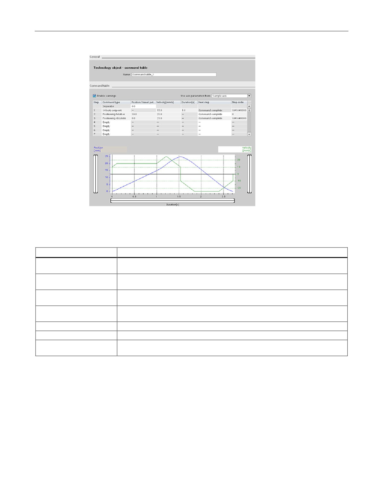
You can create the desired movement sequence in the "Command Table" configuration
window and check the result against the graphic view in the trend diagram.
326
Motion control is easy
10.7 Motion control instructions
You can select the command types that are to be used for processing the command table.
Up to 32 jobs can be entered. The commands are processed in sequence.
Table 10- 46 MC_CommandTable command types
Command type
Description
Empty
The empty serves as a placeholder for any commands to be added. The empty entry is
ignored when the command table is processed
Halt
Pause axis.
Note: The command only takes place after a "Velocity setpoint" command.
Positioning Relative
Positions the axis based upon distance. The command moves the axis by the given dis-
tance and velocity.
Positioning Absolute
Positions the axis based upon location. The command moves the axis to the given loca-
tion, using the velocity specified.
Velocity setpoint
Moves the axis at the given velocity.
Wait
Waits until the given period is over. "Wait" does not stop an active traversing motion.
Separator
Adds a "Separator" line above the selected line. The separator line allows more than one
profile to be defined in a single command table.
Prerequisites for MC_CommandTable execution:
● The technology object TO_Axis_PTO V2.0 must be correctly configured.
● The technology object TO_CommandTable_PTO must be correctly configured.
● The axis must be released.
327
Motion control is easy
10.7 Motion control instructions
Override response
The MC_CommandTable task can be
The new MC_CommandTable task aborts the
aborted by the following motion control
following active motion control tasks:
tasks:
• MC_Home Mode = 3
• MC_Home Mode = 3
• MC_Halt
• MC_Halt
• MC_MoveAbsolute
• MC_MoveAbsolute
• MC_MoveRelative
• MC_MoveRelative
• MC_MoveVelocity
• MC_MoveVelocity
• MC_MoveJog
• MC_MoveJog
• MC_CommandTable
• MC_CommandTable
• The current motion control job with the
launch of the first "Positioning Relative",
"Positioning Absolute", "Velocity setpoint"
or "Halt" command
10.7.11
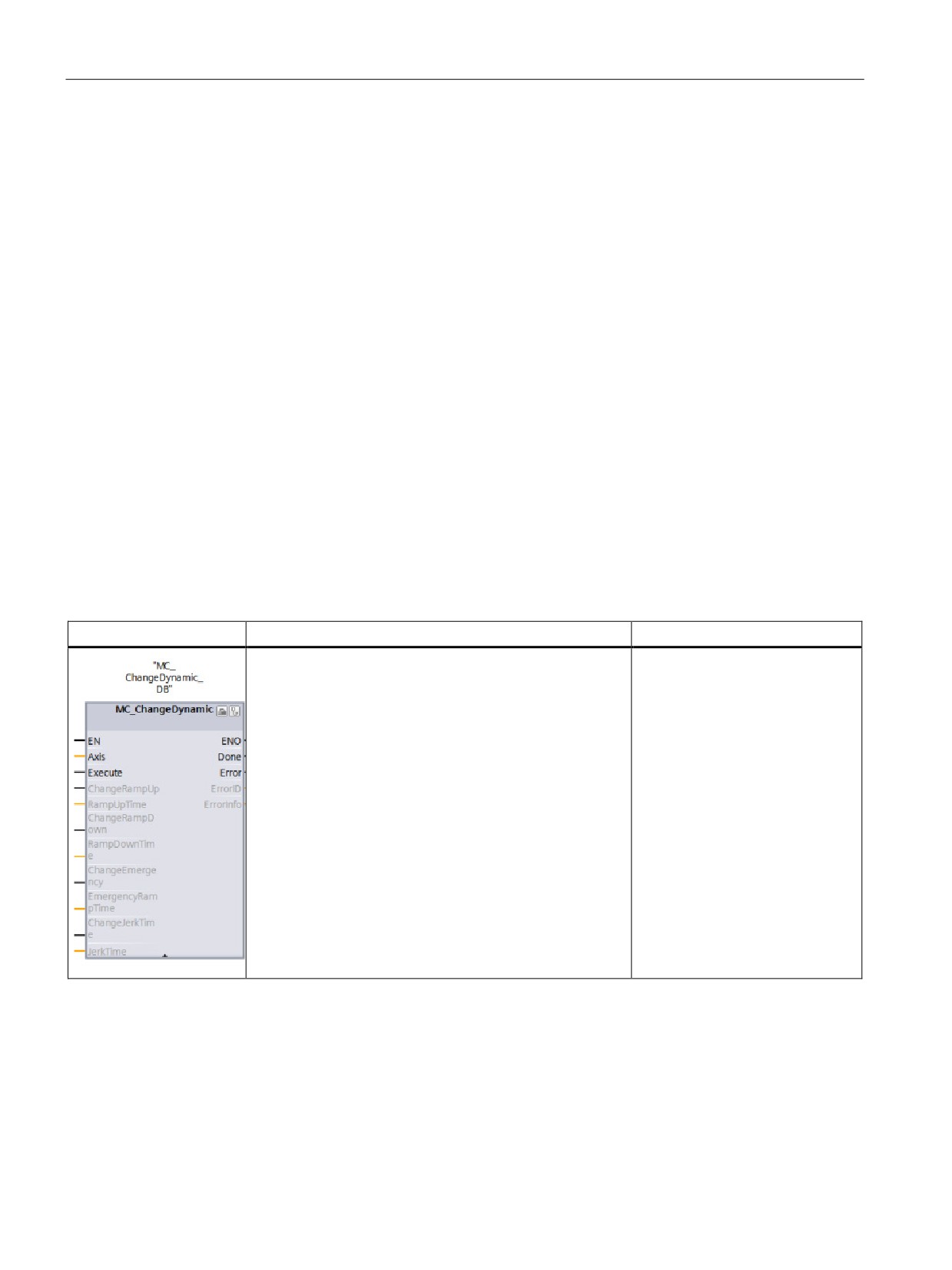
MC_ChangeDynamic (Change dynamc settings for the axis) instruction
Table 10- 47 MC_ChangeDynamic instruction
LAD / FBD
SCL
Description
"MC_ChangeDynamic_DB"(
Changes the dynamic settings of
Execute:=_bool_in_,
a motion control axis:
ChangeRampUp:=_bool_in_,
• Change the ramp-up time
RampUpTime:=_real_in_,
(acceleration) value
ChangeRampDown:=_bool_in_,
• Change the ramp-down time
RampDownTime:=_real_in_,
(deceleration) value
ChangeEmergency:=_bool_in_,
EmergencyRampTime:=_real_in_,
• Change the emergency stop
ChangeJerkTime:=_bool_in_,
ramp-down time (emergency
JerkTime:=_real_in_,
stop deceleration) value
Done=>_bool_out_,
• Change the smoothing time
Error=>_bool_out_,
(jerk) value
ErrorID=>_word_out_,
ErrorInfo=>_word_out_);
1
STEP 7 automatically creates the DB when you insert the instruction.
2
In the SCL example, "MC_ChangeDynamic_DB " is the name of the instance DB.
328

Motion control is easy
10.7 Motion control instructions
Table 10- 48 Parameters for the MC_ChangeDynamic instruction
Parameter and type
Data type
Description
Axis
IN
TO_Axis_1
Axis technology object
Execute
IN
Bool
Start of the command with a positive edge. Default value:
FALSE
ChangeRampUp
IN
Bool
TRUE = Change ramp-up time in line with input parameter
"RampUpTime". Default value: FALSE
RampUpTime
IN
Real
Time (in seconds) to accelerate from standstill to the configured
maximum velocity without jerk limit. Default value: 5.00
The change will influence the tag <Axis name>. Con-
fig.DynamicDefaults.Acceleration. The effectiveness of the
change is shown in the description of this tag.
ChangeRampDown
IN
Bool
TRUE = Change ramp-down time in line with input parameter
"RampDownTime". Default value: FALSE
RampDownTime
IN
Real
Time (in seconds) to decelerate axis from the configured maxi-
mum velocity to standstill without jerk limiter. Default value: 5.00
The change will influence the tag <Axis name>. Con-
fig.DynamicDefaults.Deceleration. The effectiveness of the
change is shown in the description of this tag.
ChangeEmergency
IN
Bool
TRUE = Change emergency stop ramp-down time in line with
input parameter "EmergencyRampTime" Default value: FALSE
EmergencyRampTime
IN
Real
Time (in seconds) to decelerate the axis from configured maxi-
mum velocity to standstill without jerk limiter in emergency stop
mode. Default value: 2.00
The change will influence the tag <Axis name>. Con-
fig.DynamicDefaults.EmergencyDeceleration. The effectiveness
of the change is shown in the description of this tag.
ChangeJerkTime
IN
Bool
TRUE = Change smoothing time according to the input parame-
ter "JerkTime". Default value: FALSE
JerkTime
IN
Real
Smoothing time (in seconds) used for the axis acceleration and
deceleration ramps. Default value: 0.25
The change will influence the tag <Axis name>. Con-
fig.DynamicDefaults.Jerk. The effectiveness of the change is
shown in the description of this tag.
Done
OUT
Bool
TRUE = The changed values have been written to the technolo-
gy data block. The description of the tags will show when the
change becomes effective. Default value: FALSE
Error
OUT
Bool
TRUE = An error occurred during execution of the command.
The cause of the error can be found in parameters "ErrorID" and
"ErrorInfo". Default value: FALSE
ErrorID
OUT
Word
Error identifier. Default value: 16#0000
ErrorInfo
IN
Word
Error information. Default value: 16#0000
Prerequisites for MC_ ChangeDynamic execution:
● The technology object TO_Axis_PTO V2.0 must be correctly configured.
● The axis must be released.
329
Motion control is easy
10.7 Motion control instructions
Override response
An MC_ChangeDynamic command cannot be aborted by any other Motion Control
command.
A new MC_ChangeDynamic command does not abort any active Motion Control jobs.
Note
The input parameters "RampUpTime", "RampDownTime", "EmergencyRampTime" and
"RoundingOffTime" can be specified with values that makes the resultant axis parameters
"acceleration", "delay", "emergency stop-delay" and "jerk" outside the permissible limits.
Make sure you keep the MC_ChangeDynamic parameters within the limits of the dynamic
configuration settings for the axis technology object.
10.7.12
MC_WriteParam (write parameters of a technology object) instruction
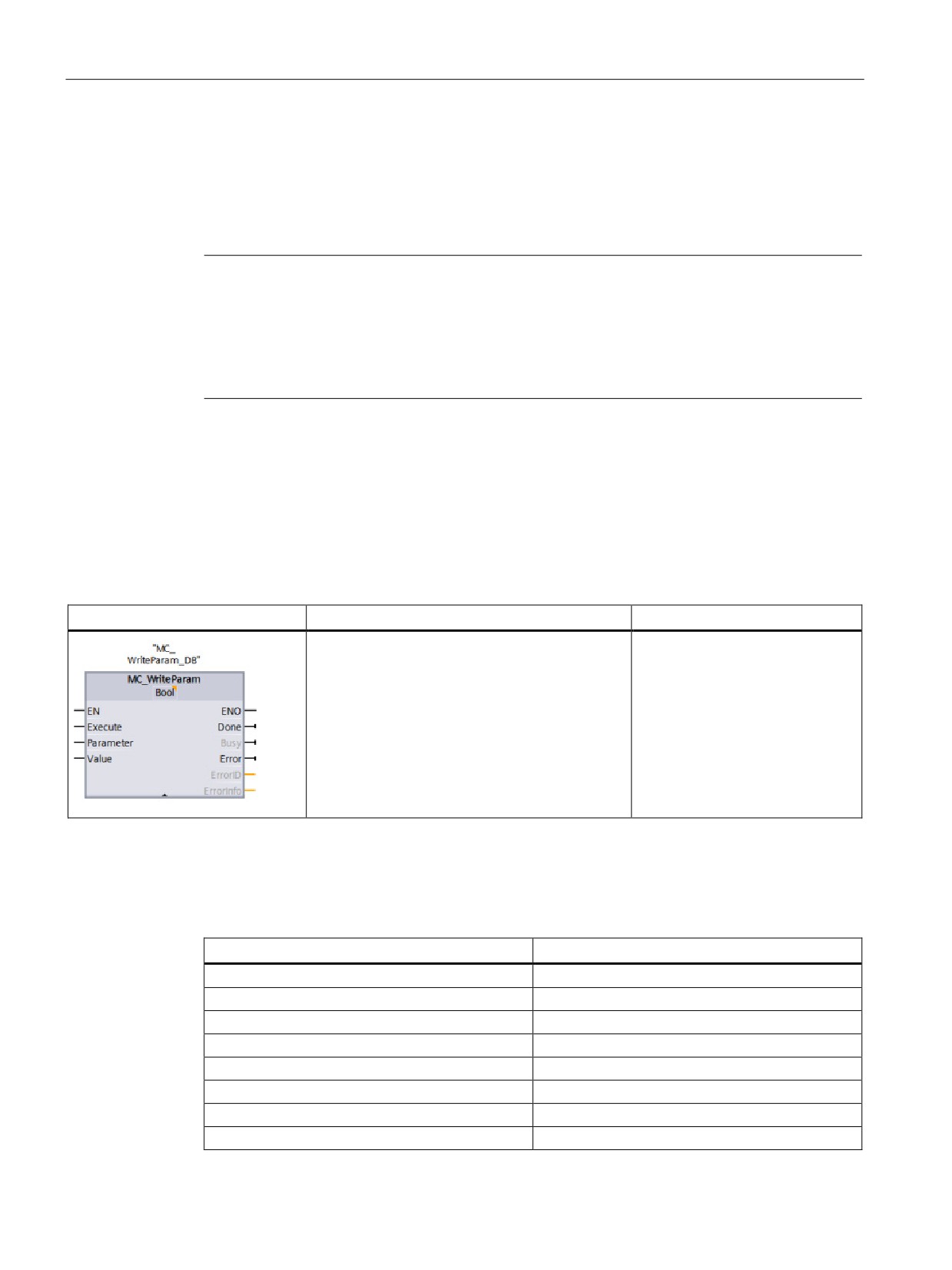
You use the MC_WriteParam instruction to write a select number of parameters to change
the functionality of the axis from the user program.
Table 10- 49 MC_WriteParam instruction
LAD / FBD
SCL
Description
"MC_WriteParam_DB"(
You use the MC_WriteParam
Parameter:=_variant_in_,
instruction to write to public pa-
Value:=_variant_in_,
rameters (for example, accelera-
Execute:=_bool_in_,
tion and user DB values).
Done:=_bool_out_,
Error:=_real_out_,
ErrorID:=_word_out_,
ErrorInfo:=_word_out_);
1
STEP 7 automatically creates the DB when you insert the instruction.
2
In the SCL example, "MC_WriteParam_DB" is the name of the instance DB.
You can write to the parameters that are public. You cannot write to "MotionStatus" and
"StatusBits". The valid parameters are listed in the table below:
Writeable parameter name
Writeable parameter name
Actor.InverseDirection
DynamicDefaults.Acceleration
Actor.DirectionMode
DynamicDefaults.Deceleration
Actor.DriveParameter.PulsesPerDriveRevolution
DynamicDefaults.Jerk
Sensor[1].ActiveHoming.Mode
DynamicDefaults.EmergencyDeceleration
Sensor[1].ActiveHoming.SideInput
PositionLimitsHW.Active
Sensor[1].ActiveHoming.Offset
PositionLimitsHW.MaxSwitchedLevel
Sensor[1].ActiveHoming.SwitchedLevel
PositionLimitsHW.MinSwitchedLevel
Sensor[1].PassiveHoming.Mode
PositionLimitsSW.Active
330

Motion control is easy
10.7 Motion control instructions
Writeable parameter name
Writeable parameter name
Sensor[1].PassiveHoming.SideInput
PositionLimitsSW.MinPosition
Sensor[1].PassiveHoming.SwitchedLevel
PositionLimitsSW.MaxPosition
Units.LengthUnit
Homing.AutoReversal
Mechanics.LeadScrew
Homing.ApproachDirection
DynamicLimits.MinVelocity
Homing.ApproachVelocity
DynamicLimits.MaxVelocity
Homing.ReferencingVelocity
Table 10- 50 Parameters for the MC_WriteParam instruction
Parameter and type
Data type
Description
PARAMNAME
IN
Variant
Name of parameter where value is written
VALUE
IN
Variant
Value to write to assigned parameter
EXECUTE
IN
Bool
Start the instruction. Default value: FALSE
DONE
OUT
Bool
Value has been written. Default value: FALSE
BUSY
OUT
Bool
If TRUE, the instruction is operating. Default value: FALSE
ERROR
OUT
Real
If TRUE, an error occurred. Default value: FALSE
ERRORID
OUT
Word
ID of the error
ERRORINFO
OUT
Word
Related information to the ERRORID
Table 10- 51 Condition codes for ERRORID and ERRORINFO
ERRORID
ERRORINFO
Description
(W#16#...)
(W#16#...)
0
0
Successful change of an Axis TO-DB parameter
8410[1]
0028[1]
Set an invalid parameter (Axis TO-DB parameter with incorrect length)
8410[1]
0029[1]
Set an invalid parameter (no Axis TO-DB parameter)
8410[1]
002B[1]
Set an Invalid parameter (read-only Axis TO-DB parameter)
8410[1]
002C[1]
Set a valid parameter, but axis is not disabled
Config
Config
Set a valid parameter (public read-only Axis TO-DB parameter) out-of-range
Error[2]
Error[2]
Config
Config
Set a valid parameter (public Axis TO-DB parameter) out-of-range
Error[3]
Error[3]
[1] Error at MC_WriteParam
[2] Error at MC_Power
[3] Error at MC_Power and MC_MoveXXX or MC_CommandTable
331
Motion control is easy
10.7 Motion control instructions
10.7.13
MC_ReadParam instruction (read parameters of a technology object) instruction
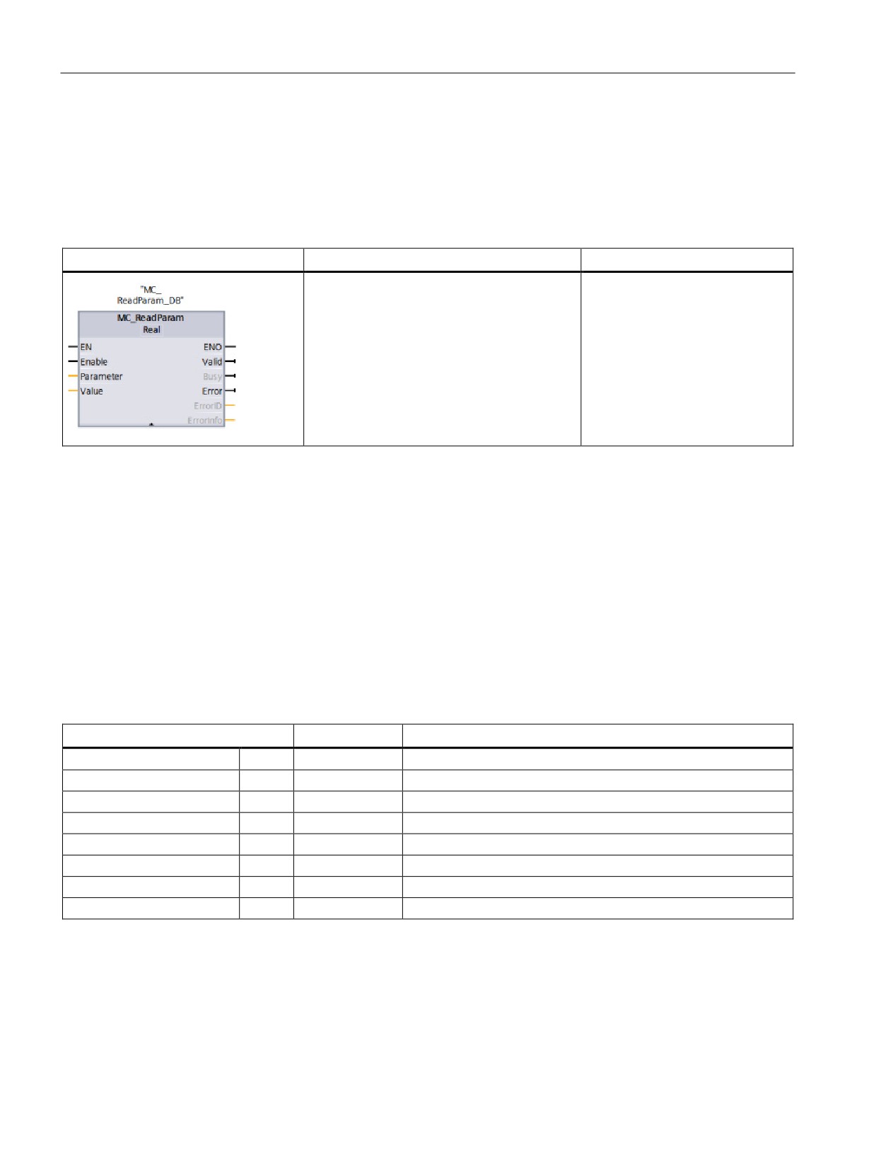
You use the MC_ReadParam instruction to read a select number of parameters that indicate
the current position, velocity, and so forth of the axis defined in the Axis input.
Table 10- 52 MC_ReadParam instruction
LAD / FBD
SCL
Description
"MC_ReadParam_DB"(
You use the MC_ReadParam
Enable:=_bool_in_,
instruction to read single status
Parameter:=_variant_in_,
values, independent of the cycle
Value:=_variant_in_out_,
control point.
Valid:=_bool_out_,
Busy:=_bool_out_,
Error:=_real_out_,
ErrorID:=_word_out_,
ErrorInfo:=_word_out_);
1
STEP 7 automatically creates the DB when you insert the instruction.
2
In the SCL example, "MC_ReadParam_DB " is the name of the instance DB.
The MC_ReadParam instruction works on an enable behavior. As long as the input "Enable"
is true the instruction reads the specified "Parameter" to the "Value" storage location.
The "MotionStatus" "Position" value updates at each Cycle Control Point (CCP) based upon
the current HSC value.
The "MotionStatus" "Velocity" value is the command velocity at the end of the current
segment (updated ~10ms). The MC_ReadParam can also read this value.
If an error occurs, the instruction switches to an error state that can only be reset by a new
rising edge at the input "Enable".
Table 10- 53 Parameters for the MC_ReadParam instruction
Parameter and type
Data type
Description
ENABLE
IN
Bool
Start the instruction. Default value: FALSE
PARAMETER
IN
Variant
Pointer to the TO-parameter that is to be read
VALID
OUT
Bool
If TRUE, the value has been read. Default value: FALSE
BUSY
OUT
Bool
If TRUE, the instruction is operating. Default value: FALSE
ERROR
OUT
Real
If TRUE, an error occurred. Default value: FALSE
ERRORID
OUT
Word
ID of the error. Default value: 0
ERRORINFO
OUT
Word
Related information to the ERRORID. Default value: 0
VALUE
INOUT
Variant
Pointer to the location where the read value is stored
332

Motion control is easy
10.7 Motion control instructions
Table 10- 54 Condition codes for ERRORID and ERRORINFO
ERRORID
ERRORINFO
Description
(W#16#...)
(W#16#...)
0
0
Successful read of a parameter
8410
0028
Invalid parameter (incorrect length)
8410
0029
Invalid parameter (no TO-DB)
8410
0030
Invalid parameter (not readable)
8411
0032
Invalid parameter (wrong value)
TO parameters
The axis "MotionStatus" consists of four values. You will want to monitor changes in these
values, which can be read while the program is running:
Variable name
Data type
Readable through
MC_ReadParam
MotionStatus:
Structure
No
• Position
REAL
Yes
• Velocity
REAL
Yes
• Distance
REAL
Yes
• TargetPosition
REAL
Yes
333
Motion control is easy
10.7 Motion control instructions
334
Easy to use the online tools
11
11.1
Going online and connecting to a CPU
You must establish an online connection between the programming device and CPU for
loading programs and project engineering data as well as for activities such as the following:
● Testing user programs
● Displaying and changing the operating mode of the CPU (Page 336)
● Displaying and setting the date and time of day of the CPU (Page 346)
● Displaying the module information
● Comparing and synchronizing (Page 345) offline to online program blocks
● Uploading and downloading program blocks
● Displaying diagnostics and the diagnostics buffer (Page 346)
● Using a watch table (Page 338) to test the user program by monitoring and modifying
values
● Using a force table to force values in the CPU (Page 340)
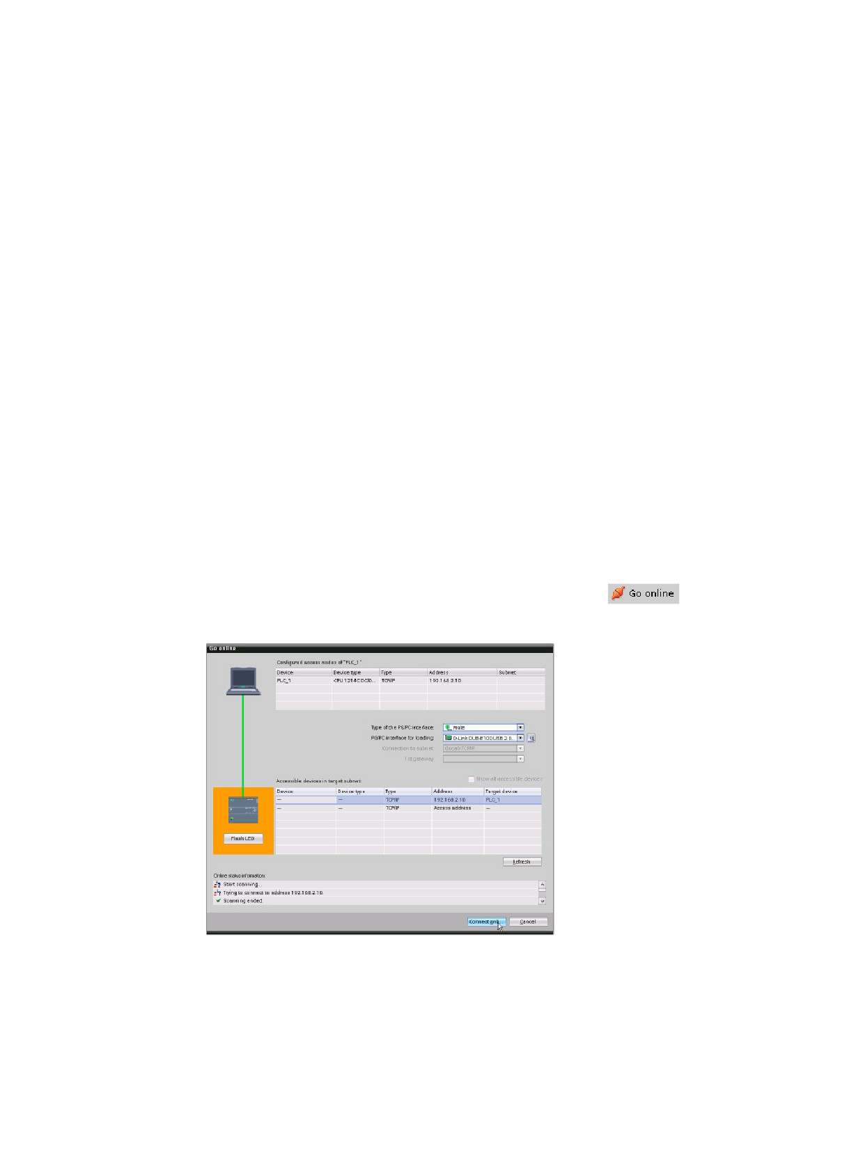
To establish an online connection to a configured CPU, click
the CPU from the Project Navigation tree and click the "Go
online" button from the Project View:
If this is the first time to go
online with this CPU, you
must select the type of PG/PC
interface and the specific
PG/PC interface from the Go
Online dialog before estab-
lishing an online connection to
a CPU found on that inter-
face.
You have now connected your programming device to the CPU. The orange color frames
indicate an online connection. You can now use the Online & diagnostics tools from the
Project tree and the Online tools task card.
335
Easy to use the online tools
11.2 Interacting with the online CPU
11.2
Interacting with the online CPU
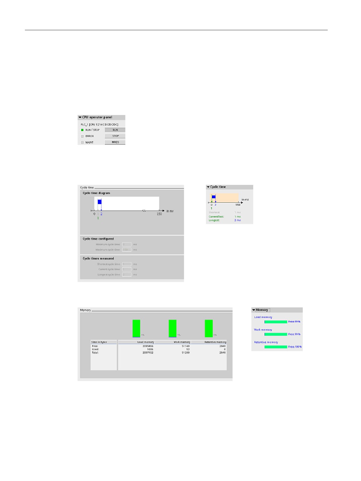
The "Online tools" task card in the project view displays an operator panel that shows the
operating mode of the online CPU. The operator panel also allows you to change the
operating mode of the online CPU. Use the button on the operator panel to change the
operating mode (STOP or RUN). The operator panel also provides an MRES button for
resetting the memory.
The color of the RUN/STOP indicator shows the current operating
mode of the CPU: yellow indicates STOP mode, and green indicates
RUN mode.
To use the operator panel, you must establish an online connection between STEP 7 and
the CPU. After you select the CPU in the device configuration or display a code block in the
online CPU, you can display the operator panel from the "Online tools" task card.
You can monitor the cycle time of an online CPU.
You can also view the memory usage of the CPU.
336
Easy to use the online tools
11.3 Going online to monitor the values in the CPU
11.3
Going online to monitor the values in the CPU
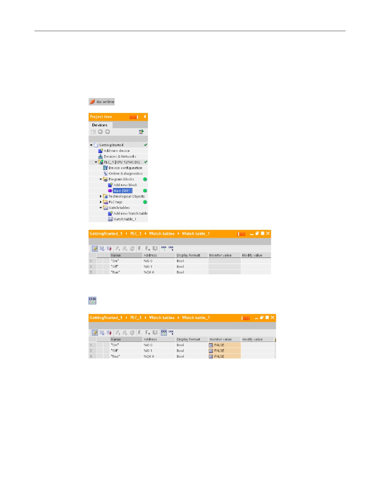
To monitor the tags, you must have an online connection to the CPU. Simply click the "Go
online" button in the toolbar.
When you have connected to the CPU, STEP 7 turns the headers of
the work areas orange.
The project tree displays a comparison of the offline project and the
online CPU. A green circle means that the CPU and the project are
synchronized, meaning that both have the same configuration and
user program.
Tag tables show the tags. Watch tables can also show the tags, as
well as direct addresses.
To monitor the execution of the user program and to display the values of the tags,
click the "Monitor all" button in the toolbar.
The "Monitor value" field shows the value for each tag.
337
Easy to use the online tools
11.4 Displaying status of the user program is easy
11.4
Displaying status of the user program is easy
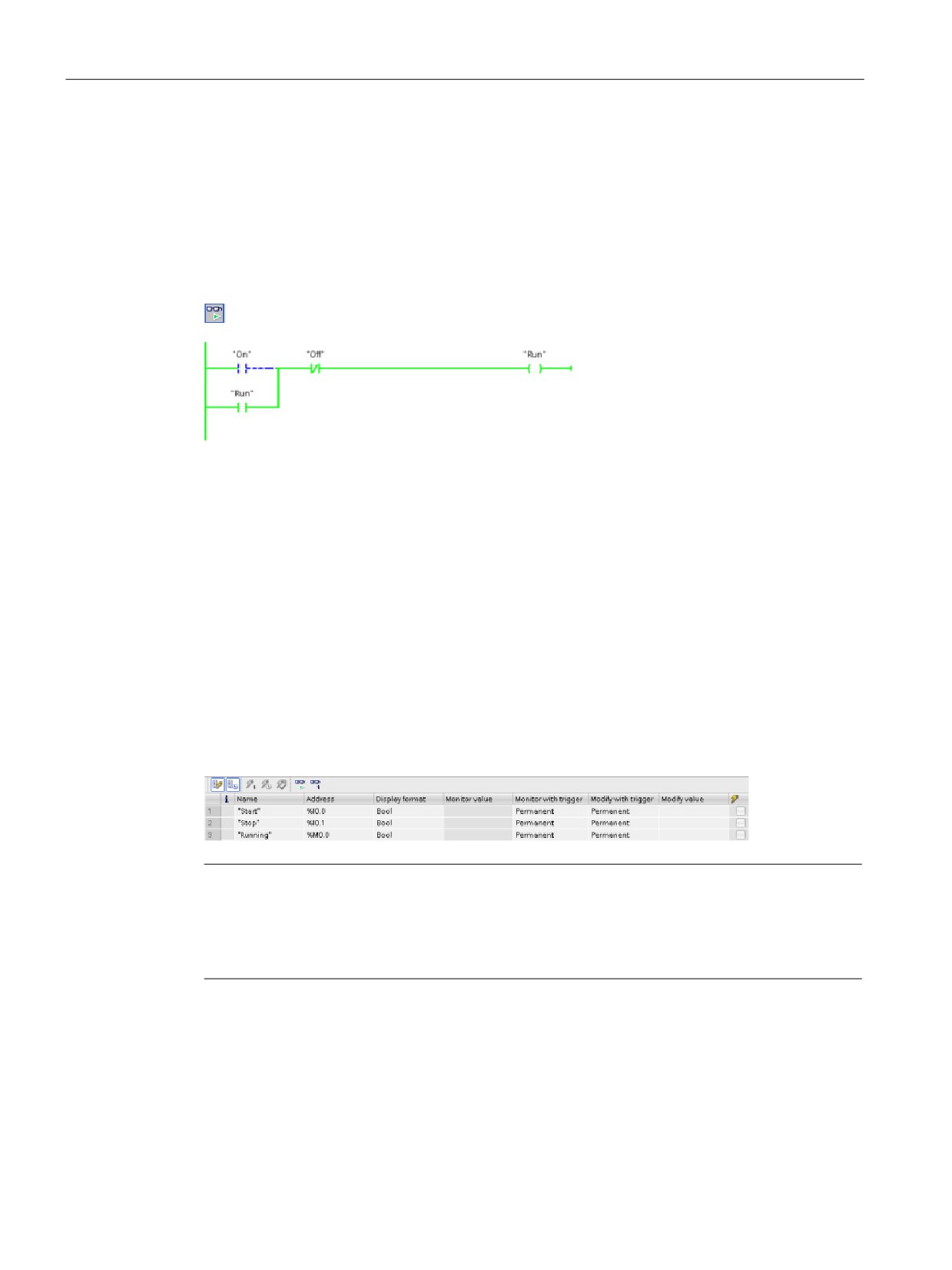
You can monitor the status of up to 50 tags in the LAD and FBD program editors. Use the
editor bar to display the LAD editor. The editor bar allows you to change the view between
the open editors without having to open or close the editors.
In the toolbar of the program editor, click the "Monitoring on/off" button to display the status
of your user program.
The network in the program editor displays power flow in green.
You can also right-click on the instruction or parameter to modify the value for the instruction.
11.5
Using a watch table for monitoring the CPU
A watch table allows you to monitor or modify data points while the CPU executes your user
program. These data points can be inputs (I), outputs (Q), M memory, a DB, or peripheral
inputs (such as "On:P" or "I 3.4:P"). You cannot accurately monitor the physical outputs
(such as Q0.0:P) because the monitor function can only display the last value written from Q
memory and does not read the actual value from the physical outputs.
The monitoring function does not change the program sequence. It presents you with
information about the program sequence and the data of the program in the CPU. You can
also use the "Modify value" function to test the execution of your user program.
Note
The digital I/O points used by the high-speed counter (HSC), pulse-width modulation (PWM),
and pulse-train output (PTO) devices are assigned during device configuration. When digital
I/O point addresses are assigned to these devices, the values of the assigned I/O point
addresses cannot be modified by the "Force" function of the watch table.
With a watch table, you can monitor or modify the values of the individual tags, choosing
from the following options:
● At the beginning or the end of the scan cycle
● When the CPU changes to STOP mode
● "Permanently" (with the value not being reset after a STOP to RUN transition)
338
Easy to use the online tools
11.5 Using a watch table for monitoring the CPU
To create a watch table:
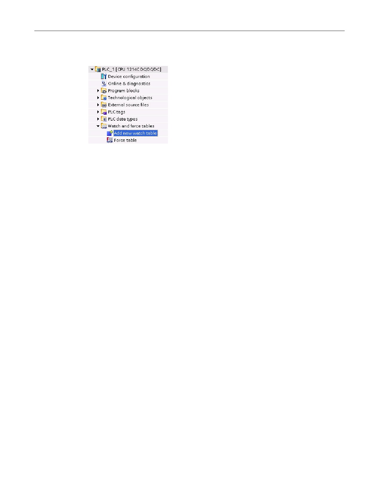
1. Double-click "Add new watch table" to open a new
watch table.
2. Enter the tag name to add a tag to the watch
table.
To monitor the tags, you must have an online connection to the CPU. The following options
are available for modifying tags:
● "Modify now" immediately changes the value for the selected addresses for one scan
cycle.
● "Modify with trigger" changes the values for the selected addresses.
This function does not provide feedback to indicate that the selected addresses were
actually modified. If feedback of the change is required, use the "Modify now" function.
● "Enable peripheral outputs" allows you to turn on the peripheral outputs when the CPU is
in STOP mode. This feature is useful for testing the wiring of the output modules.
The various functions can be selected using the buttons at the top of a watch table. Enter the
tag name to monitor and select a display format from the dropdown selection. With an online
connection to the CPU, clicking the "Monitor" button displays the actual value of the data
point in the "Monitor value" field.
339

Easy to use the online tools
11.6 Using the force table
11.6
Using the force table
A force table provides a "force" function that overwrites the value for an input or output point
to a specified value for the peripheral input or peripheral output address. The CPU applies
this forced value to the input process image prior to the execution of the user program and to
the output process image before the outputs are written to the modules.
Note
The force values are stored in the CPU and not in the force table.
You cannot force an input (or "I" address) or an output (or "Q" address). However, you can
force a peripheral input or peripheral output. The force table automatically appends a ":P" to
the address (for example: "On":P or "Run":P).
In the "Force value" cell, enter the value for the input or output to be forced. You can then
use the check box in the "Force" column to enable forcing of the input or output.
Use the "Start or replace forcing" button to force the value of the tags in the force
table. Click the "Stop forcing" button to reset the value of the tags.
In the force table, you can monitor the status of the forced value for an input. However, you
cannot monitor the forced value of an output.
You can also view the status of the forced value in the program editor.
Note
When an input or output is forced in a force table, the force actions become part of the
project configuration. If you close STEP 7, the forced elements remain active in the CPU
program until they are cleared. To clear these forced elements, you must use STEP 7 to
connect with the online CPU and then use the force table to turn off or stop the force function
for those elements.
340
Easy to use the online tools
11.6 Using the force table
The CPU allows you to force input and output point(s) by specifying the physical input or
output address (I_:P or Q_:P) in the force table and then starting the force function.
In the program, reads of physical inputs are overwritten by the forced value. The program
uses the forced value in processing. When the program writes a physical output, the output
value is overwritten by the force value. The forced value appears at the physical output and
is used by the process.
When an input or output is forced in the force table, the force actions become part of the
user program. Even though the programming software has been closed, the force selections
remain active in the operating CPU program until they are cleared by going online with the
programming software and stopping the force function. Programs with forced points loaded
on another CPU from a memory card will continue to force the points selected in the
program.
If the CPU is executing the user program from a write-protected memory card, you cannot
initiate or change the forcing of I/O from a watch table because you cannot override the
values in the write-protected user program. Any attempt to force the write-protected values
generates an error. If you use a memory card to transfer a user program, any forced
elements on that memory card will be transferred to the CPU.
Note
Digital I/O points assigned to HSC, PWM, and PTO cannot be forced
The digital I/O points used by the high-speed counter (HSC), pulse-width modulation (PWM),
and pulse-train output (PTO) devices are assigned during device configuration. When digital
I/O point addresses are assigned to these devices, the values of the assigned I/O point
addresses cannot be modified by the force function of the force table.
341
Easy to use the online tools
11.6 Using the force table
Startup
RUN
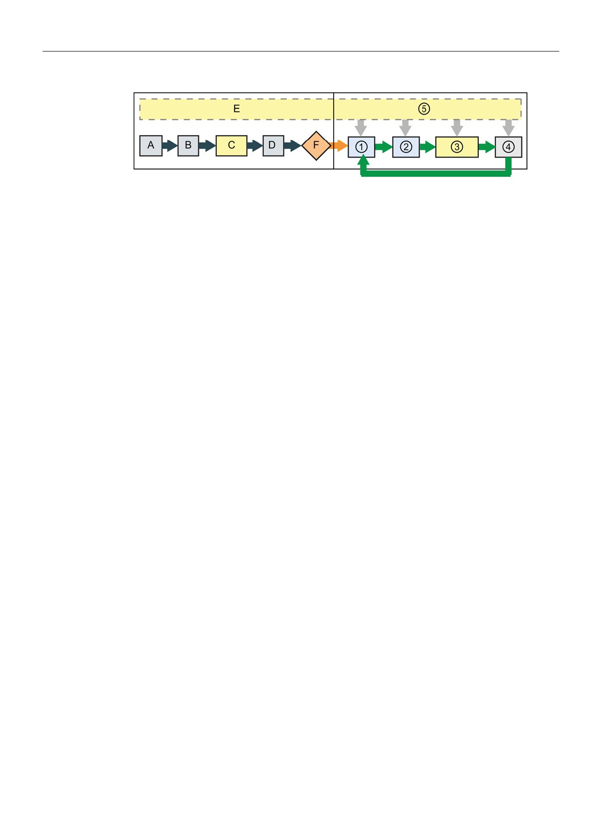
A The clearing of the I memory area is not
① While writing Q memory to the physical out-
affected by the Force function.
puts, the CPU applies the force value as the
outputs are updated.
B The initialization of the outputs values is
② When reading the physical inputs, the CPU
not affected by the Force function.
applies the force values just prior to copying
the inputs into I memory.
C During the execution of the startup OBs,
③ During the execution of the user program
the CPU applies the force value when
(program cycle OBs), the CPU applies the
the user program accesses the physical
force value when the user program accesses
input.
the physical input or writes the physical out-
put.
D The storing of interrupt events into the
④ Handling of communication requests and self-
queue is not affected.
test diagnostics are not affected by the Force
function.
E The enabling of the writing to the out-
⑤ The processing of interrupts during any part of
puts is not affected.
the scan cycle is not affected.
342
Easy to use the online tools
11.7 Capturing the online values of a DB to reset the start values
11.7
Capturing the online values of a DB to reset the start values
You can capture the current values being monitored in an online CPU to become the start
values for a global DB.
●
You must have an online connection to the CPU.
●
The CPU must be in RUN mode.
●
You must have opened the DB in STEP 7.
Use the "Show a snapshot of the monitored values" button to capture the current val-
ues of the selected tags in the DB. You can then copy these values into the "Start val-
ue" column of the DB.
1.
In the DB editor, click the "Monitor all tags" button. The "Monitor value" column displays
the current data values.
2.
Click the "Show a snapshot of the monitored values" button to display the current values
in the "Snapshot" column.
3.
Click the "Monitor all" button to stop monitoring the data in the CPU.
4.
Copy a value in the "Snapshot" column for a tag.
- Select a value to be copied.
- Right-click the selected value to display the context menu.
- Select the "Copy" command.
5.
Paste the copied value into the corresponding "Start value" column for the tag. (Right-
click the cell and select "Paste" from the context menu.)
6.
Save the project to configure the copied values as the new start values for the DB.
7.
Compile and download the DB to the CPU. The DB uses the new start values after the
CPU goes to RUN mode.
Note
The values that are shown in the "Monitor value" column are always copied from the
CPU. STEP 7 does not check whether all values come from the same scan cycle of the
CPU.
343
Easy to use the online tools
11.8 Uploading elements of the project
11.8
Uploading elements of the project
You can also copy the program blocks from an online CPU or a memory card attached to
your programming device.
Prepare the offline project for the copied program blocks:
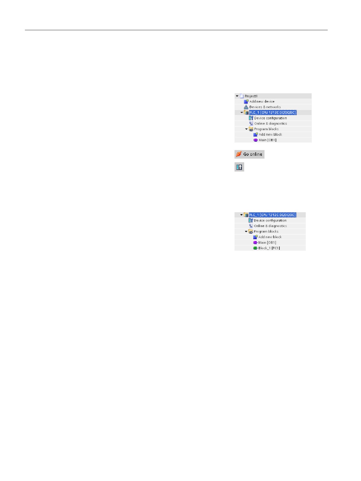
1. Add a CPU device that matches the online CPU.
2. Expand the CPU node once so that the "Program
blocks" folder is visible.
To upload the program blocks from the online CPU to the
offline project, follow these steps:
1. Click the "Program blocks" folder in the offline project.
2. Click the "Go online" button.
3. Click the "Upload" button.
4. Confirm your decision from the Upload dialog
(Page 335).
When the upload is complete, STEP 7 displays all of the
uploaded program blocks in the project.
344
Easy to use the online tools
11.9 Comparing offline and online CPUs
11.9
Comparing offline and online CPUs
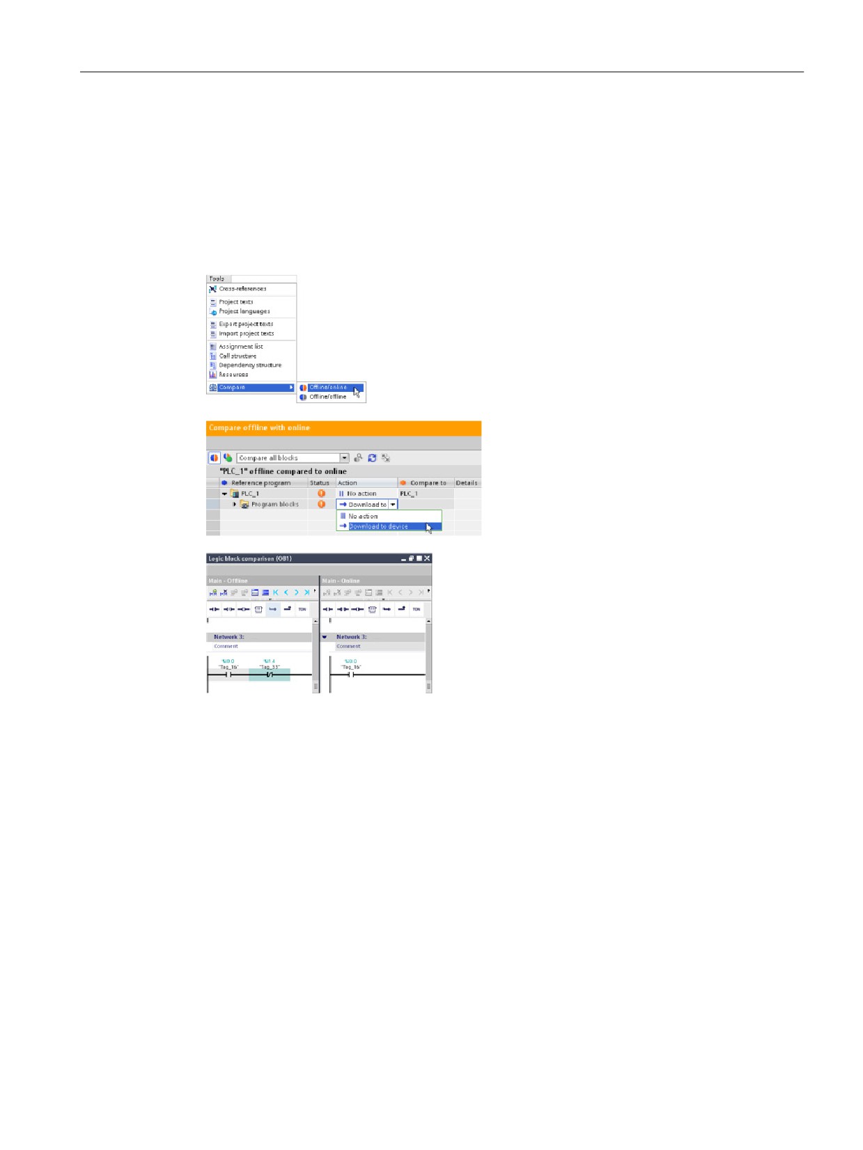
You can compare the code blocks in an online CPU with the code blocks in your project. If
the code blocks of your project do not match the code blocks of the online CPU, the
"Compare" editor allows you to synchronize your project with the online CPU by downloading
the code blocks of your project to the CPU, or by deleting blocks from the project that do not
exist in the online CPU.
Select the CPU in your project.
Use the "Compare Offline/online" command to open the "Com-
pare" editor. (Access the command either from the "Tools"
menu or by right-clicking the CPU in your project.)
Click in the "Action" column for an object to
select whether to delete the object, take no
action, or download the object to the device.
Click the "Synchronize" button to load the code
blocks.
Right-click an object in the "Compare to" column and
select "Start detailed comparison" button to show the
code blocks side-by-side.
The detailed comparison highlights the differences
between the code blocks of online CPU and the code
blocks of the CPU in your project.
345
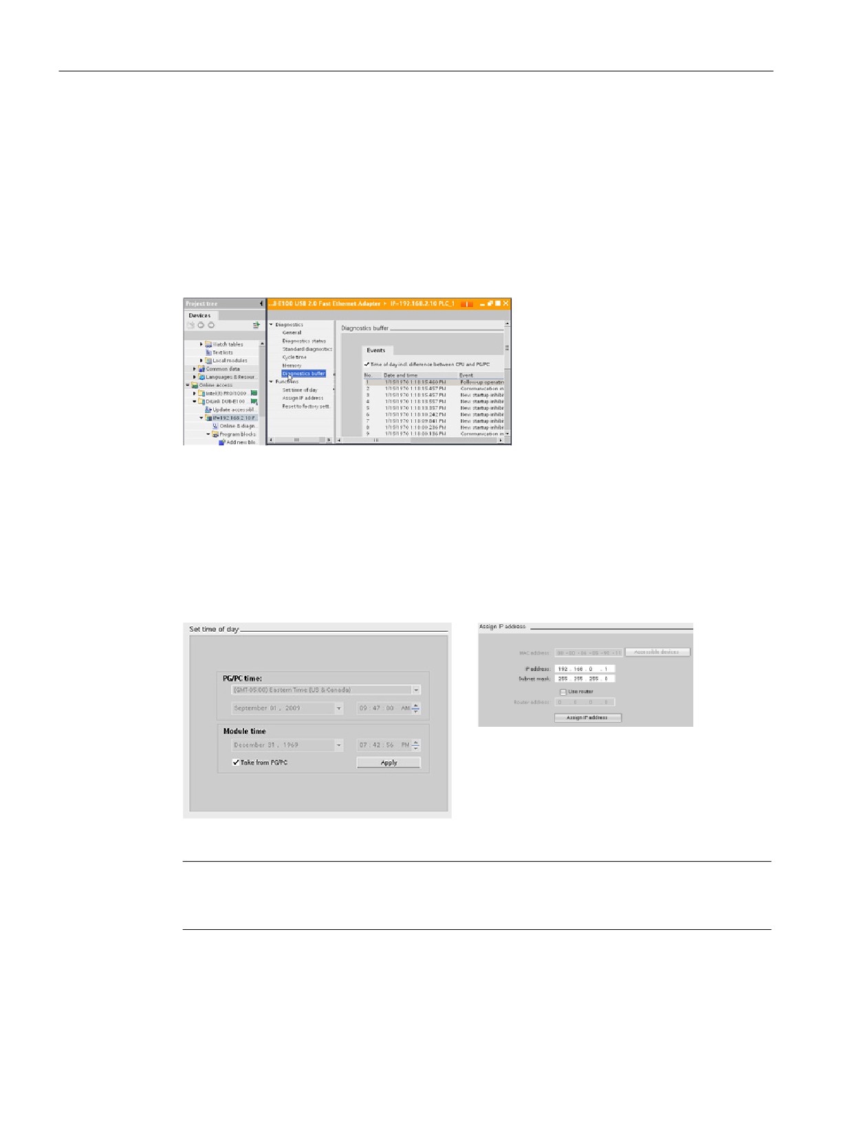
Easy to use the online tools
11.10 Displaying the diagnostic events
11.10
Displaying the diagnostic events
The CPU provides a diagnostic buffer that contains an entry for each diagnostic event, such
as transition of the CPU operating mode or errors detected by the CPU or modules. To
access the diagnostic buffer, you must be online.
Each entry includes a date and time the event occurred, an event category, and an event
description. The entries are displayed in chronological order, with the most recent event at
the top.
While the CPU maintains power, up to
50 most recent events are available in
this log. When the log is full, a new
event replaces the oldest event in the
log.
When power is lost, the ten most re-
cent events are saved.
11.11
Setting the IP address and time of day
You can set the IP address and time of day in the online CPU. After accessing "Online &
diagnostics" from the Project tree for an online CPU, you can display or change the IP ad-
dress. You can also display or set the time and date parameters of the online CPU.
Note
This feature is available only for a CPU that either has only a MAC address (has not yet
been assigned an IP address) or has been reset to factory settings.
346

Easy to use the online tools
11.12 Resetting to factory settings
11.12
Resetting to factory settings
You can reset an S7-1200 to its original factory settings under the following conditions:
● The CPU has an online connection.
● The CPU is in STOP mode.
Note
If the CPU is in RUN mode and you start the reset operation, you can place it in STOP
mode after acknowledging a confirmation prompt.
Procedure
To reset a CPU to its factory settings, follow these steps:
1. Open the Online and Diagnostics view of the CPU.
2. Select "Reset to factory settings" from the "Functions" folder.
3. Select the "Retain IP address" check box if you want to retain the IP address or the
"Delete IP address" check box if you want to delete the IP address.
4. Click the "Reset" button.
5. Acknowledge the confirmation prompt with "OK".
Result
The module switches to STOP mode if necessary, and it resets the factory settings. The
CPU perfoms the following actions:
With memory card installed in CPU
Without memory card installed in CPU
• Clears the diagnostics buffer
• Clears the diagnostics buffer
• Resets the time of day
• Resets the time of day
• Restores work memory from the memory card
• Clears the work memory and internal load
memory
• Sets all operand areas to configured initial
values
• Sets all operand areas to configured initial
values
• Sets all parameters to their configured values
• Sets all parameters to their configured values
• Retains or deletes the IP address based on
the selection you made. (The MAC address is
• Retains or deletes the IP address based on
fixed and is never changed.)1
the selection you made. (The MAC address is
fixed and is never changed.)1
• Deletes the control data record, if present
• Deletes the control data record, if present
1
If you selected "Retain IP address", the CPU sets the IP address, subnet mask, and router ad-
dress (if used) to the settings in your hardware configuration, unless you have modified these val-
ues from the user program or another tool, in which case the CPU restores the modified values.
347
Easy to use the online tools
11.13 Updating firmware
11.13
Updating firmware
You can update the firmware of the connected CPU from the STEP 7 online and diagnostics
tools.
To perform a firmware update, follow these steps:
1. Open the Online and Diagnostics view of the connected CPU.
2. Select "Firmware update" from the "Functions" folder.
3. Click the Browse button and navigate to the location that contains the firmware update
file. This could be a location on your hard drive to which you have downloaded an
firmware update file from the service and support Web site
4. Select a file that is compatible with your module. For a selected file, the table displays the
compatible modules.
5. Click the "Run update" button. Follow the dialogs, if necessary, to change the operating
mode of your CPU.
STEP 7 displays progress dialogs as it loads the firmware update. When it finishes, it
prompts you to start the module with the new firmware.
Note
If you do not choose to start the module with the new firmware, the previous firmware
remains active until you reset the module, for example by cycling power. The new firmware
becomes active only after you reset the module.
You can also perform a firmware update by one of the following additional methods:
● Using a memory card (Page 61)
● Using the Web server "Module Information" standard Web page (Page 254)
348
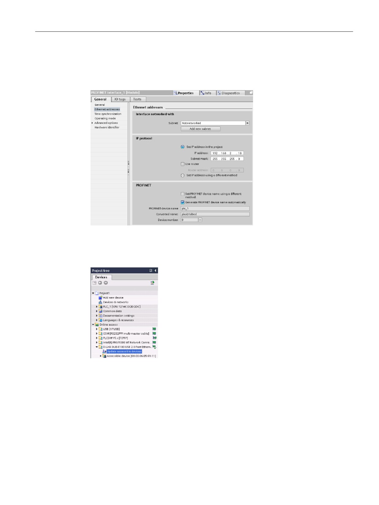
Easy to use the online tools
11.14 Downloading an IP address to an online CPU
11.14
Downloading an IP address to an online CPU
To assign an IP address, you must perform the following tasks:
• Configure the IP
address for the CPU
(Page 85).
• Save and download the
configuration to the
CPU.
The IP address and subnet mask for the CPU must be compatible with the IP address and
subnet mask of the programming device. Consult your network specialist for the IP address
and subnet mask for your CPU.
If the CPU has not been previously configured, you can also
use "Online access" to set the IP address.
An IP address that you have downloaded with the device con-
figuration will not be lost on a power cycle of the PLC.
After you have downloaded the device configuration with the IP address, you can see the IP
address under the "Online access" folder.
349
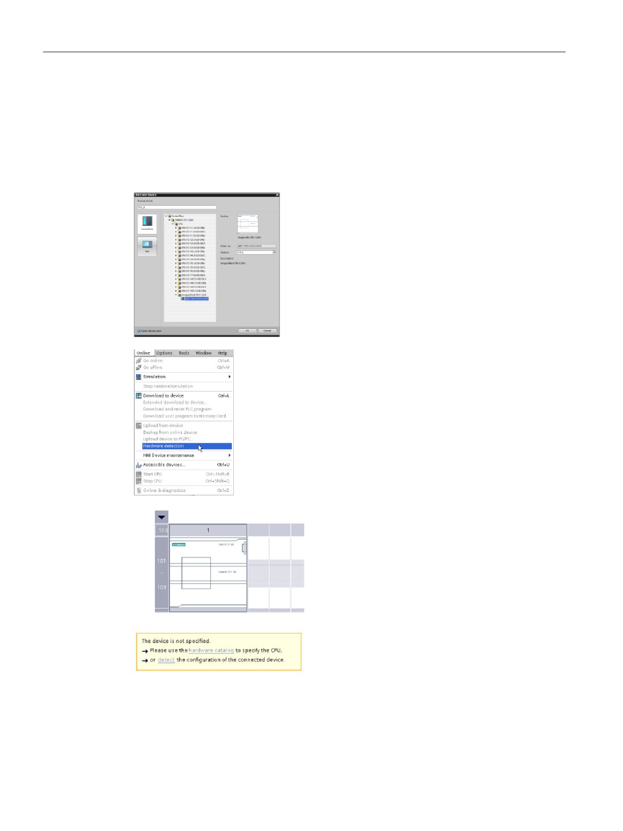
Easy to use the online tools
11.15 Using the "unspecified CPU" to upload the hardware configuration
11.15
Using the "unspecified CPU" to upload the hardware configuration
If you have a physical CPU that you can connect to the programming device, it is easy to
upload the configuration of the hardware.
You must first connect the CPU to your programming device, and you must create a new
project.
In the device configuration (Project view or Portal view),
add a new device, but select the "unspecified CPU" in-
stead of selecting a specific CPU. STEP 7 creates an
unspecified CPU.
After creating the unspecified CPU, you can upload the hard-
ware configuration for the online CPU.
• From the program editor, you select the "Hardware
detection" command from the "Online" menu.
• From the device configuration editor, you select the option
for detecting the configuration of the connected device
After you select the CPU from the online dialog, STEP 7 uploads the hardware configuration
from the CPU, including any modules (SM, SB, or CM). The IP address is not uploaded. You
must go to "Device configuration" to manually configure the IP address.
350

Easy to use the online tools
11.16 Downloading in RUN mode
11.16
Downloading in RUN mode
The CPU supports "Download in RUN mode". This capability is intended to allow you to
make small changes to a user program with minimal disturbance to the process being
controlled by the program. However, implementing this capability also allows massive
program changes that could be disruptive or even dangerous.
WARNING
Risks with downloading in RUN mode
When you download changes to the CPU in RUN mode, the changes immediately affect
process operation. Changing the program in RUN mode can result in unexpected system
operation, which could cause death or serious injury to personnel, and/or damage to
equipment.
Only authorized personnel who understand the effects of RUN mode changes on system
operation should perform a download in RUN mode.
The "Download in RUN mode" feature allows you to make changes to a program and
download them to your CPU without switching to STOP mode:
● You can make minor changes to your current process without having to shut down (for
example, change a parameter value).
● You can debug a program more quickly with this feature (for example, invert the logic for
a normally open or normally closed switch).
You can make the following program block and tag changes and download them in RUN
mode:
● Create, overwrite, and delete Functions (FC), Function Blocks (FB), and Tag tables.
● Create, delete, and overwrite Data Blocks (DB) and instance data blocks for Function
Blocks (FB). You can add to DB structures and download them in RUN mode. The CPU
can maintain the values of existing block tags and initialize the new data block tags to
their initial values, or the CPU can set all data block tags to initial values, depending on
your configuration settings. You cannot download a web server DB (control or fragment)
in RUN mode.
● Overwrite Organization Blocks (OB); however, you cannot create or delete OBs.
You can download a maximum number of twenty blocks in RUN mode at one time. If you
must download more than twenty blocks, you must place the CPU in STOP mode.
If you download changes to a real process (as opposed to a simulated process, which you
might do in the course of debugging a program), it is vital to think through the possible safety
consequences to machines and machine operators before you download.
Note
If the CPU is in RUN mode and program changes have been made, STEP 7 always tries to
download in RUN first. If you do not want this to happen, you must put the CPU into STOP.
If the changes made are not supported in "Download in RUN", STEP 7 prompts the user that
the CPU must go to STOP.
351
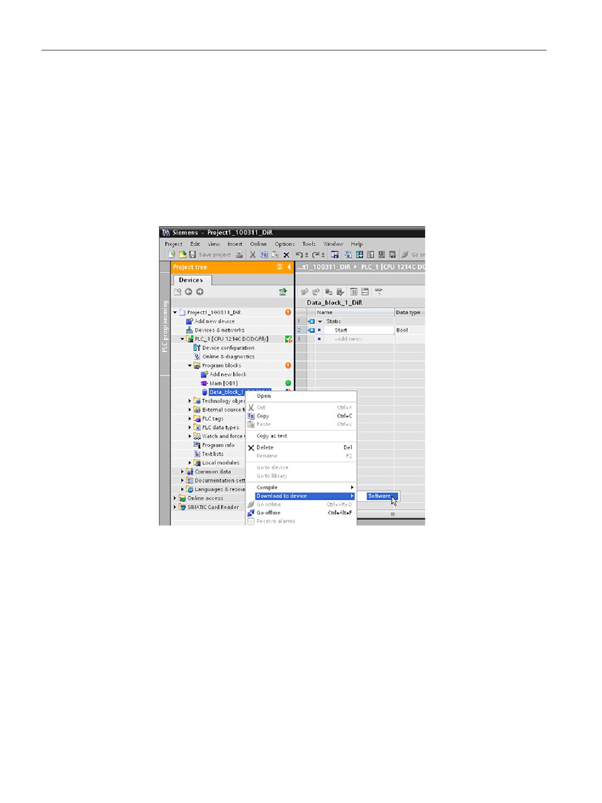
Easy to use the online tools
11.16 Downloading in RUN mode
11.16.1
Changing your program in RUN mode
To change the program in RUN mode, your must first ensure that the CPU and program
meet the prerequisites, and then follow these steps:
1. To download your program in RUN mode, select one of the following methods:
- Select the "Download to device" command from the "Online" menu.
- Click the "Download to device" button in the toolbar.
- In the "Project tree", right-click "Program blocks" and select the "Download to device >
Software" command.
If the program compiles successfully, STEP 7 starts to download the program to the CPU.
2. When STEP 7 prompts you to load your program or cancel the operation, click "Load" to
download the program to the CPU.
352
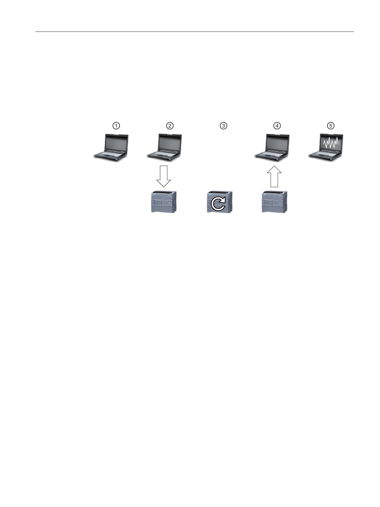
Easy to use the online tools
11.17 Tracing and recording CPU data on trigger conditions
11.17
Tracing and recording CPU data on trigger conditions
STEP 7 provides trace and logic analyzer functions with which you can configure variables
for the PLC to trace and record. You can then upload the recorded trace data to your
programming device and use STEP 7 tools to analyze, manage, and graph your data. You
use the Traces folder in the STEP 7 project tree to create and manage traces.
The following figure shows the various steps of the trace feature:
① Configure the trace in the trace editor of STEP 7. You can configure the data values to record,
the recording duration, the recording frequency, and the trigger condition.
② Transfer the trace configuration from STEP 7 to the PLC.
③ The PLC executes the program, and when the trigger condition occurs, begins recording the
trace data.
④ Transfer the recorded values from the PLC to STEP 7.
⑤ Use the tools in STEP 7 to analyze the data, display it graphically, and save it.
The maximum size of a trace is 512 Kbytes per trace.
Access to examples
See the STEP 7 information system for details about how to program a trace, how to
download the configuration, upload the trace data, and display the data in the logic analyzer.
You can find detailed examples there in the "Using online and diagnostics functions > Using
the trace and logic analyzer function" chapter.
In addition the online manual "Industry Automation SINAMICS/SIMATIC Using the trace and
an excellent reference.
353
Easy to use the online tools
11.17 Tracing and recording CPU data on trigger conditions
354
IO-Link is easy
12
12.1
Overview of IO-Link technology
IO-Link is an innovative communication technology for sensors and actuators defined by the
PROFIBUS user organization (PNO). IO-Link is an international standard according to IEC
61131-9. It is based on a point-to-point connection between the sensors and actuators
(slaves) and the controller (master). It does not therefore represent a bus system, but is an
upgrade of the conventional point-to-point connection.
In addition to cyclic operating data, extensive parameter and diagnostic data is transmitted
by the connected sensors/actuators. The same 3-wire connecting cable that is used for
standard sensor technology is used for data transmission.
12.2
Components of an IO-Link system
An IO-Link system consists of IO-Link devices (usually sensors, actuators, or combinations
thereof), a standard 3-wire sensor/actuator cable, and an IO-Link master. The master can be
a device with any design and degree of protection.
An IO-Link master can have one or more ports. The SM 1278 4xIO-Link Master has four
ports. One IO-Link device or one standard sensor/actuator can be connected to each port.
IO-Link is a point-to-point communication system.
12.3
After power-up
At power-up, the IO-Link device is always in SIO mode (standard I/O mode). The ports of the
master can have different configurations. See the IO-Link chapter in the S7-1200
Programmable Controller System Manual for details.
If a port is set to SIO mode, the master acts on this port like a normal digital input. If the port
is set to IO-Link mode (communication mode), the master tries to find the connected IO-Link
device. This process is called wake-up.
During wake-up, the master sends a defined signal and waits for the slave device to
respond. Initially, the master attempts to do this with the highest possible baud rate. If this is
unsuccessful, the master tries the next lower baud rate. The master tries to address the
device three times with each baud rate. The device always supports only one defined baud
rate. If the master receives a response (that is, if the device has been woken up), both will
start communication. At first, they exchange the communication parameters, and then they
start the cyclical exchange of process data.
If the slave device is removed during operation, the master detects the communication abort,
reports it with fieldbus specificity to the controller, and attempts to wake up the device again
cyclically. After another successful wake-up, the communication parameters are read out
again, validated if applicable, and then the cyclic communication channel starts again.
355
IO-Link is easy
12.4 IO-Link protocol
12.4
IO-Link protocol
The IO-Link system can exchange three types of data:
● Cyclic process data (process data inputs, outputs) → Cyclic data
● Device parameters (on-request data objects) → Acyclic data
● Events → Acyclic data
The IO-Link device only sends data after being requested by the IO-Link master to do so.
Process data is sent after the IDLE frame of the master, and the master explicitly requests
device parameter data and events.
12.5
Configuration in the fieldbus
The IO-Link master appears on the fieldbus as a normal fieldbus node and is integrated via
the appropriate device description in the relevant network configurator. These files describe
the communication properties and other properties of the IO-Link master, such as the
number of ports. They do not indicate which IO-Link devices are connected.
However, the IO-Link Device Description (IODD) has been defined for full transparent
representation of the system architecture up to the IO-Link device. With the help of the IODD
and the IO-Link configuration tool S7-PCT, you can configure which IO-Link device is
connected to which port of your IO-Link master.
See the S7-PCT help system and the S7-1200 Programmable Controller System Manual for
detailed configuration information.
12.6
IO-Link and your STEP 7 program
The IO-Link master programs acyclic communication with an IO-Link device using the
IOL_CALL function block (FB) in your STEP 7 S7-1200 controller program. The IOL_CALL
FB indicates the IO-Link master your program uses, and which ports the master uses for
data exchange.
for details on working with the IOL_CALL FB. Enter "IO-Link" in the website's search box to
access information about IO-Link products and their use.
356
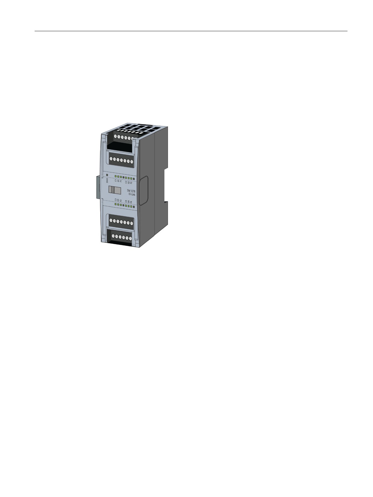
IO-Link is easy
12.7 The SM 1278 4xIO-Link Master
12.7
The SM 1278 4xIO-Link Master
The SM 1278 4xIO-Link Master is a 4-port module that functions as both a signal module
and a communication module. Each port can operate in the IO-Link mode, single 24 VDC
digital input or 24 VDC digital output. You can connect up to four IO-Link devices (3-wire
connection) or four standard actuators or standard encoders.
357
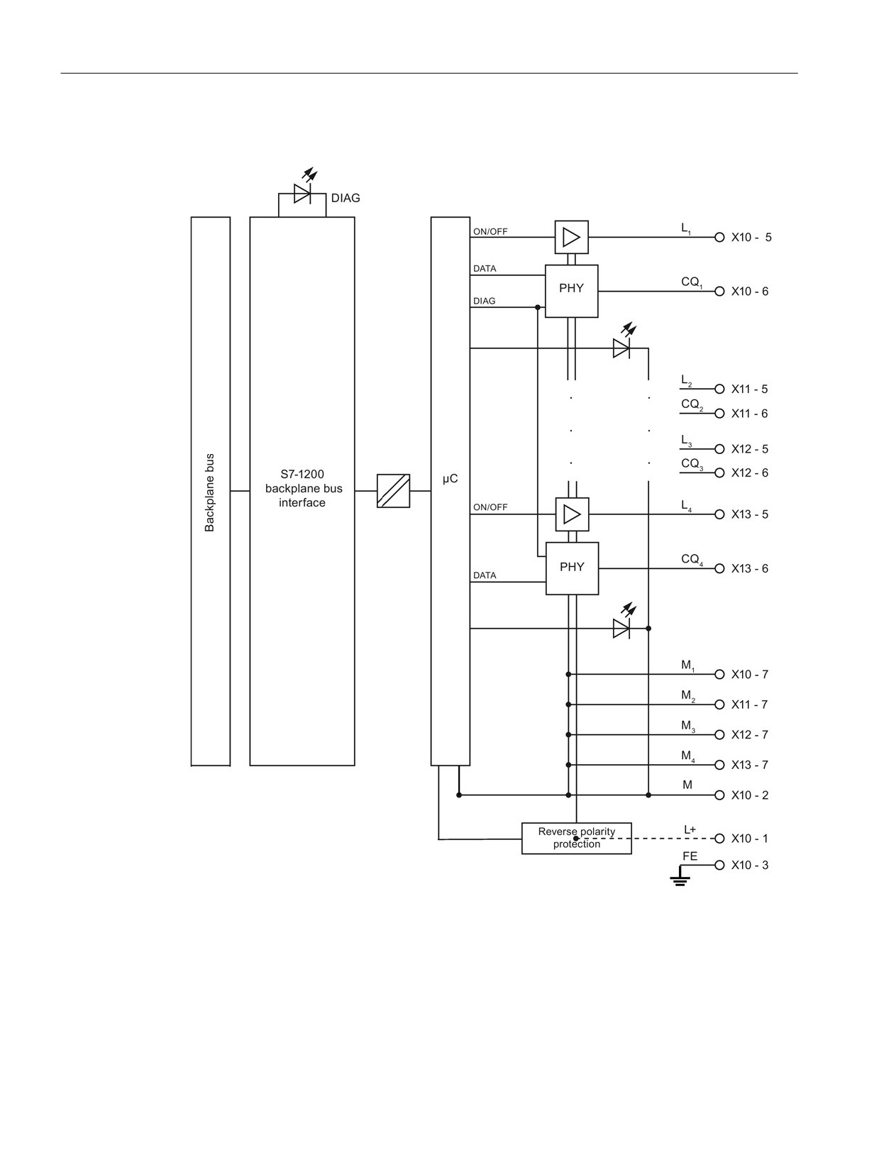
IO-Link is easy
12.7 The SM 1278 4xIO-Link Master
SM 1278 4xIO-Link Master block diagram
358
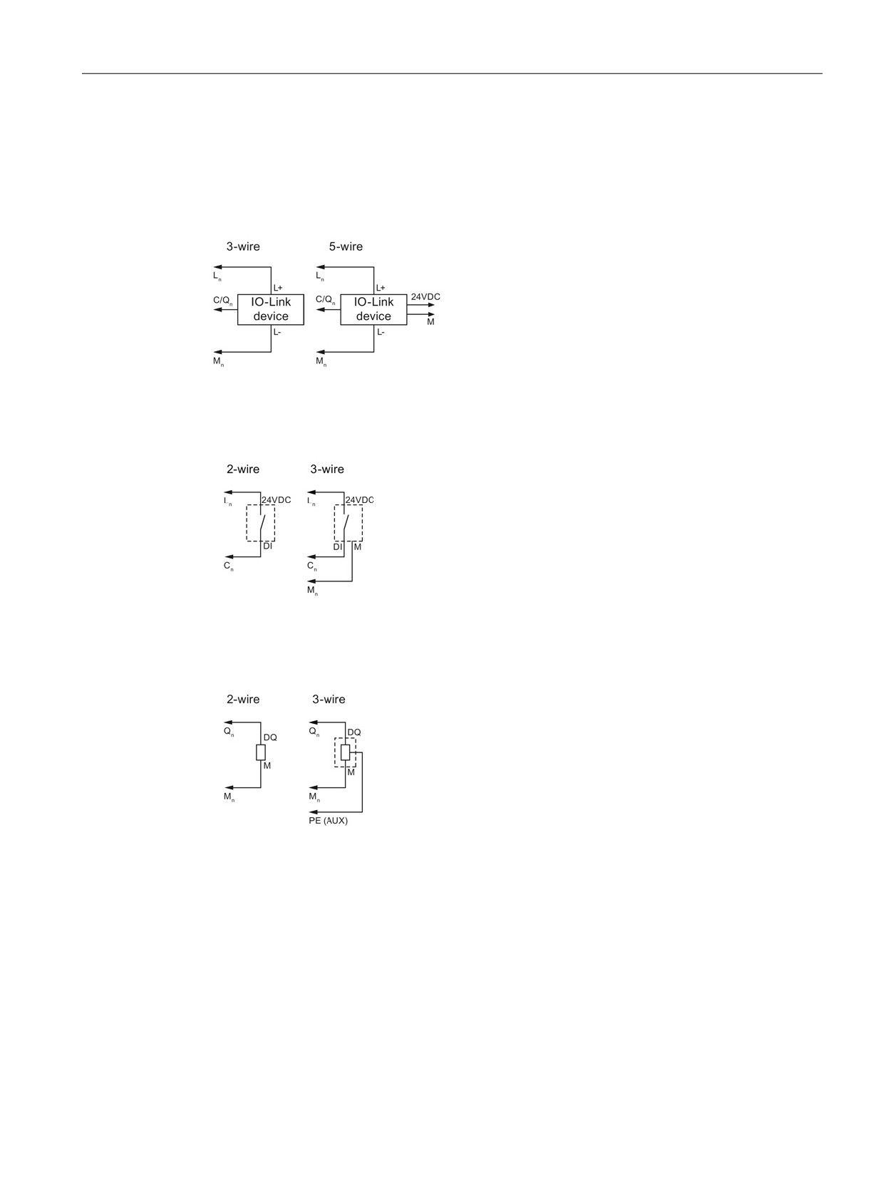
IO-Link is easy
12.7 The SM 1278 4xIO-Link Master
Connection examples
The following illustration shows the configuration for IO-Link operating mode (3-wire and
5-wire), where n = port number:
The following illustration shows the configuration for DI operating mode (2-wire and 3-wire),
where n = port number:
The following illustration shows the configuration for DQ operating mode (2-wire and 3-wire),
where n = port number:
Detailed information on using and configuring the SM 1278 4xIO-Link Master
For detailed information on the SM 1278 4xIO-Link Master, including diagrams, connection,
parameterization, diagnostic alarms and more, refer to the S7-1200 Programmable
Controller System Manual.
359
IO-Link is easy
12.7 The SM 1278 4xIO-Link Master
360
Technical specifications
A
A.1
General technical specifications
Standards compliance
The S7-1200 automation system design conforms with the following standards and test
specifications. The test criteria for the S7-1200 automation system are based on these
standards and test specifications.
Note that not all S7-1200 models may be certified to these standards, and certification status
may change without notification. It is your responsibility to determine applicable certifications
by referring to the ratings marked on the product. Consult your local Siemens representative
if you need additional information related to the latest listing of exact approvals by part
number.
CE approval
The S7-1200 Automation System satisfies requirements and safety related objectives
according to the EC directives listed below, and conforms to the harmonized European
standards (EN) for the programmable controllers listed in the Official Journals of the
European Community.
● EC Directive 2006/95/EC (Low Voltage Directive) "Electrical Equipment Designed for Use
within Certain Voltage Limits"
- EN 61131-2:2007 Programmable controllers - Equipment requirements and tests
● EC Directive 2004/108/EC (EMC Directive) "Electromagnetic Compatibility"
- Emission standard
EN 61000-6-4:2007+A1:2011: Industrial Environment
- Immunity standard
EN 61000-6-2:2005: Industrial Environment
● EC Directive 94/9/EC (ATEX) "Equipment and Protective Systems Intended for Use in
Potentially Explosive Atmosphere"
- EN 60079-15:2010: Type of Protection 'n'
The CE Declaration of Conformity is held on file available to competent authorities at:
Siemens AG
Sector Industry
I IA AS FA DH AMB
Postfach 1963
D-92209 Amberg
Germany
361
Technical specifications
A.1 General technical specifications
cULus approval
Underwriters Laboratories Inc. complying with:
● Underwriters Laboratories, Inc.: UL 508 Listed (Industrial Control Equipment)
● Canadian Standards Association: CSA C22.2 Number 142 (Process Control Equipment)
Note
The SIMATIC S7-1200 series meets the CSA standard.
The cULus logo indicates that the S7-1200 has been examined and certified by
Underwriters Laboratories (UL) to standards UL 508 and CSA 22.2 No. 142.
FM approval
Factory Mutual Research (FM)
Approval Standard Class Number 3600 and 3611
Approved for use in:
Class I, Division 2, Gas Group A, B, C, D, Temperature Class T3C Ta = 60 °C
Class I, Zone 2, IIC, Temperature Class T3 Ta = 60 °C
Canadian Class I, Zone 2 Installation per CEC 18-150
IMPORTANT EXCEPTION: See Technical Specifications for the number of inputs or outputs
allowed on simultaneously. Some models are de-rated for Ta = 60 °C.
WARNING
Substitution of components can impair the suitability for Class I, Division 2 and Zone 2.
Repair of units should only be performed by an authorized Siemens Service Center.
IECEx approval
EN 60079-0: Explosive Atmospheres - General Requirements
EN60079-15: Electrical Apparatus for Potentially Explosive Atmospheres;
Type of protection ‘nA’
IECEX FMG14.0012X
Ex nA IIC Tx Gc
IECEx rating information may appear on the product with the FM Hazardous Location
information.
Only products marked with an IECEx rating are approved. Consult your local Siemens
representative if you need additional information related to the latest listing of exact
approvals by part number.
Relay models are not included in IECEx approvals.
Refer to specific product marking for temperature rating.
Install modules in a suitable enclosure providing a minimum degree of protection of IP54
according to IEC 60079-15.
362