Siemens simatic S7-1200. Manual (2015) - page 4

Easy to communicate between devices
7.10 PtP, USS, and Modbus communication protocols
PtP over PROFIBUS or PROFINET
Version V4.1 of the S7-1200 CPU together with STEP 7 V13 SP1 extends the capability of
PtP to use a PROFINET or PROFIBUS distributed I/O rack to communicate to various
devices (RFID readers, GPS device, and others):
● PROFINET (Page 147): You connect the Ethernet interface of the S7-1200 CPU to a
PROFINET interface module. PtP communication modules in the rack with the interface
module can then provide serial communications to the PtP devices.
● PROFIBUS (Page 157): You insert a PROFIBUS communication module in the left side
of the rack with the S7-1200 CPU. You connect the PROFIBUS communication module
to a rack containing a PROFIBUS interface module. PtP communication modules in the
rack with the interface module can then provide serial communications to the PtP
devices.
For this reason, the S7-1200 supports two sets of PtP instructions:
● Legacy point-to-point instructions: These instructions existed prior to version V4.0 of the
S7-1200 and only work with serial communications using a CM 1241 communication
module or CB 1241 communication board.
● Point-to-point instructions (Page 185): These instructions provide all of the functionaity of
the legacy instructions, plus the ability to connect to PROFINET and PROFIBUS
distributed I/O. The point-to-point instructions allow you to configure the communications
between the PtP communication modules in the distributed I/O rack and the PtP devices.
Note
With version V4.1 of the S7-1200, you can use the point-to-point instructions for all types of
point-to-point communication: serial, serial over PROFINET, and serial over PROFIBUS.
STEP 7 provides the legacy point-to-point instructions only to support existing programs. The
legacy instructions still function, however, with V4.1 CPUs as well as V4.0 and earlier CPUs.
You do not have to convert prior programs from one set of instructions to the other.
183
Easy to communicate between devices
7.10 PtP, USS, and Modbus communication protocols
7.10.2
Using the serial communication interfaces
Two communication modules (CMs) and one communication board (CB) provide the
interface for PtP communications:
● CM 1241 RS232 (Page 426)
● CM 1241 RS422/485 (Page 425)
● CB 1241 RS485 (Page 423)
You can connect up to three CMs (of any type) plus a CB for a total of four communication
interfaces. Install the CM to the left of the CPU or another CM. Install the CB on the front of
the CPU. Refer to the installation guidelines (Page 19) for information on module installation
and removal.
The serial communication interfaces have the following characteristics:
● Have an isolated port
● Support Point-to-Point protocols
● Are configured and programmed through the point-to-point communication processor
instructions
● Display transmit and receive activity by means of LEDs
● Display a diagnostic LED (CMs only)
● Are powered by the CPU: No external power connection is needed.
Refer to the technical specifications for communication interfaces (Page 414).
LED indicators
The communication modules have three LED indicators:
● Diagnostic LED (DIAG): This LED flashes red until it is addressed by the CPU. After the
CPU powers up, it checks for CMs and addresses them. The diagnostic LED begins to
flash green. This means that the CPU has addressed the CM, but has not yet provided
the configuration to it. The CPU downloads the configuration to the configured CMs when
the program is downloaded to the CPU. After a download to the CPU, the diagnostic LED
on the communication module should be a steady green.
● Transmit LED (Tx): The transmit LED illuminates when data is being transmitted out the
communication port.
● Receive LED (Rx): This LED illuminates when data is being received by the
communication port.
The communication board provides transmit (TxD) and receive (RxD) LEDs. It has no
diagnostic LED.
184
Easy to communicate between devices
7.10 PtP, USS, and Modbus communication protocols
7.10.3
PtP instructions
The Port_Config, Send_Config, and Receive_Config instructions allow you to change the
configuration from your user program.
● Port_Config changes the port parameters such as baud rate.
● Send_Config changes the configuration of serial transmission parameters.
● Receive_Config changes the configuration of serial receiver parameters in a
communication port. This instruction configures the conditions that signal the start and
end of a received message. Messages that satisfy these conditions will be received by
the Receive_P2P instruction.
The dynamic configuration changes are not permanently stored in the CPU. After a power
cycle, the initial static configuration from the device configuration will be used.
The Send_P2P, Receive_P2P, and Receive_Reset instructions control the PtP
communication:
● Send_P2P transfers the specified buffer to the CM or CB. The CPU continues to execute
the user program while the module sends the data at the specified baud rate.
● Receive_P2P checks for messages that have been received in the CM or CB. If a
message is available, it will be transferred to the CPU.
● Receive_Reset resets the receive buffer.
Each CM or CB can buffer up to a maximum of 1K bytes. This buffer can be allocated across
multiple received messages.
The Signal_Set and Signal_Get instructions are valid only for the RS232 CM. Use these
instructions to read or set the RS232 communication signals.
The Get_Features and Set_Features instructions enable the program to read and set module
features.
185
Easy to communicate between devices
7.10 PtP, USS, and Modbus communication protocols
7.10.4
USS instructions
S7-1200 supports the USS protocol and provides instructions that are specifically designed
for communicating with drives over the RS485 port of a CM or a CB. You can control the
physical drive and the read/write drive parameters with the USS instructions. Each RS485
CM or CB supports a maximum of 16 drives.
● The USS_Port_Scan instruction handles actual communication between the CPU and all
the drives attached to one CM or CB. Insert a different USS_Port_Scan instruction for
each CM or CB in your application. Ensure that the user program executes the
USS_Port_Scan instruction fast enough to prevent a communication timeout by the drive.
Use the USS_Port_Scan instruction in a program cycle or any interrupt OB.
● The USS_Drive_Control instruction accesses a specified drive on the USS network. The
input and output parameters of the USS_Drive_Control instruction are the status and
controls for the drive. If there are 16 drives on the network, your program must have at
least 16 USS_Drive_Control instructions, with one instruction for each drive.
Ensure that the CPU executes the USS_Drive_Control instruction at the rate that is
required to control the functions of the drive. Use the USS_Drive_Control instruction only
in a program cycle OB.
● The USS_Read_Param and USS_Write_Param instructions read and write the operating
parameters of the remote drive. These parameters control the internal operation of the
drive. See the drive manual for the definition of these parameters.
Your program can contain as many of these instructions as necessary. However, only
one read or write request can be active for any one drive at any given time. Use the
USS_Read_Param and USS_Write_Param instructions only in a program cycle OB.
An instance DB contains temporary storage and buffers for all of the drives on the USS
network connected to each CM or CB. The USS instructions for a drive use the instance DB
to share the information.
186

Easy to communicate between devices
7.10 PtP, USS, and Modbus communication protocols
Calculating the time required for communicating with the drive
Communications with the drive are asynchronous to the CPU scan. The CPU typically
completes several scans before one drive communications transaction is completed.
The USS_Port_Scan interval is the time required for one drive transaction. The table below
shows the minimum USS_Port_Scan interval for each communication baud rate. Calling the
USS_Port_Scan function more frequently than the USS_Port_Scan interval will not increase
the number of transactions. The drive timeout interval is the amount of time that might be
taken for a transaction, if communications errors caused 3 tries to complete the transaction.
By default, the USS protocol library automatically does up to 2 retries on each transaction.
Table 7- 14 Calculating the time requirements
Baud rate
Calculated minimum USS_Port_Scan call
Drive message interval timeout per
Interval (milliseconds)
drive (milliseconds)
1200
790
2370
2400
405
1215
4800
212.5
638
9600
116.3
349
19200
68.2
205
38400
44.1
133
57600
36.1
109
115200
28.1
85
187

Easy to communicate between devices
7.10 PtP, USS, and Modbus communication protocols
7.10.5
Modbus instructions
The CPU supports Modbus communication over different networks:
●
Modbus RTU (Remote Terminal Unit) is a standard network communication protocol that
uses the RS232 or RS485 electrical connection for serial data transfer between Modbus
network devices. You can add PtP (Point to Point) network ports to a CPU with a RS232
or RS485 CM or a RS485 CB.
Modbus RTU uses a master/slave network where all communications are initiated by a
single Master device and slaves can only respond to a master’s request. The master
sends a request to one slave address and only that slave address responds to the
command.
●
Modbus TCP (Transmission Control Protocol) is a standard network communication
protocol that uses the PROFINET connector on the CPU for TCP/IP communication. No
additional communication hardware module is required.
Modbus TCP uses client-server connections as a Modbus communication path. Multiple
client-server connections may exist, in addition to the connection between STEP 7 and
the CPU. Mixed client and server connections are supported up to the maximum number
of connections allowed by the CPU. Each MB_SERVER connection must use a unique
instance DB and IP port number. Only 1 connection per IP port is supported. Each
MB_SERVER (with its unique instance DB and IP port) must be executed individually for
each connection.
WARNING
If an attacker can physically access your networks, the attacker can possibly read and
write data.
The TIA Portal, the CPU, and HMIs (except HMIs using GET/PUT) use secure
communication that protects against replay and "man-in-the-middle" attacks. Once
communication is enabled, the exchange of signed messages takes place in clear text
which allows an attacker to read data, but protects against unauthorized writing of data.
The TIA Portal, not the communication process, encrypts the data of know-how
protected blocks.
All other forms of communication (I/O exchange through PROFIBUS, PROFINET, AS-i,
or other I/O bus, GET/PUT, T-Block, and communication modules (CM)) have no
security features. You must protect these forms of communication by limiting physical
access. If an attacker can physically access your networks utilizing these forms of
communication, the attacker can possibly read and write data.
For security information and recommendations, please see our "Operational Guidelines
for Industrial Security" on the Service and Support site:
security/Documents/operational_guidelines_industrial_security_en.pdf
security/Documents/operational_guidelines_industrial_security_en.pdf)
Note
Modbus TCP will only operate correctly with CPU firmware release V1.02 or later. An
attempt to execute the Modbus instructions on an earlier firmware version will result in an
error.
188

Easy to communicate between devices
7.10 PtP, USS, and Modbus communication protocols
Table 7- 15 Modbus instructions
Type of communication
Instruction
Modbus RTU (RS232 or RS485)
Modbus_Comm_Load: One execution of Modbus_Comm_Load is used to set up PtP
port parameters like baud rate, parity, and flow control. After the CPU port is config-
ured for the Modbus RTU protocol, it can only be used by either the Modbus_Master
or Modbus_Slave instructions.
Modbus_Master: The Modbus master instruction enables the CPU to act as a Mod-
bus RTU master device and communicate with one or more Modbus slave devices.
Modbus_Slave: The Modbus slave instruction enables the CPU to act as a Modbus
RTU slave device and communicate with a Modbus master device.
Modbus TCP (PROFINET)
MB_CLIENT: Make client-server TCP connection, send command message, receive
response, and control the disconnection from the server.
MB_SERVER: Connect to a Modbus TCP client upon request, receive Modbus mes-
sage, and send response.
The Modbus instructions do not use communication interrupt events to control the
communication process. Your program must poll the Modbus_Master / Modbus_Slave or
MB_CLIENT/ MB_SERVER instructions for transmit and receive complete conditions.
A Modbus TCP client (master) must control the client-server connection with the
DISCONNECT parameter. The basic Modbus client actions are shown below.
1. Initiate a connection to a particular server (slave) IP address and IP port number
2. Initiate client transmission of Modbus messages and receive the server responses
3. When required, initiate the disconnection of client and server to enable connection with a
different server.
189
Easy to communicate between devices
7.10 PtP, USS, and Modbus communication protocols
190

PID is easy
8
STEP 7 provides the following PID instructions for the S7-1200 CPU:
● The PID_Compact instruction is used to control technical processes with continuous
input- and output variables.
● The PID_3Step instruction is used to control motor-actuated devices, such as valves that
require discrete signals for open- and close actuation.
● The PID_Temp instruction provides a universal PID controller that allows handling of the
specific requirements of temperature control.
Note
Changes that you make to the PID configuration and download in RUN do not take effect
until the CPU transitions from STOP to RUN mode. Changes that you make in the "PID
parameters" dialog using the "Start value control" take effect immediately.
All three PID instructions (PID_Compact, PID_3Step, and PID_Temp) can calculate the P-, I-
, and D-components during startup (if configured for "pre-tuning"). You can also configure
the instruction for "fine tuning" to allow you to optimize the parameters. You do not need to
manually determine the parameters.
Note
Execute the PID instruction at constant intervals of the sampling time (preferably in a cyclic
OB).
Because the PID loop needs a certain time to respond to changes of the control value, do
not calculate the output value in every cycle. Do not execute the PID instruction in the main
program cycle OB (such as OB 1).
The sampling time of the PID algorithm represents the time between two calculations of the
output value (control value). The output value is calculated during self-tuning and rounded to
a multiple of the cycle time. All other functions of PID instruction are executed at every call.
191
PID is easy
PID algorithm
The PID (Proportional/Integral/Derivative) controller measures the time interval between two
calls and then evaluates the results for monitoring the sampling time. A mean value of the
sampling time is generated at each mode changeover and during initial startup. This value is
used as reference for the monitoring function and is used for calculation. Monitoring includes
the current measuring time between two calls and the mean value of the defined controller
sampling time.
The output value for the PID controller consists of three components:
● P (proportional): When calculated with the "P" component, the output value is proportional
to the difference between the setpoint and the process value (input value).
● I (integral): When calculated with the "I" component, the output value increases in
proportion to the duration of the difference between the setpoint and the process value
(input value) to finally correct the difference.
● D (derivative): When calculated with the "D" component, the output value increases as a
function of the increasing rate of change of the difference between the setpoint and the
process value (input value). The output value is corrected to the setpoint as quickly as
possible.
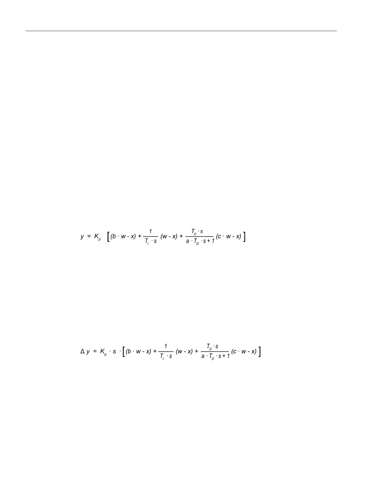
The PID controller uses the following formula to calculate the output value for the
PID_Compact instruction.
y
Output value
x
Process value
w Setpoint value
s
Laplace operator
Kp
Proportional gain
a
Derivative delay coefficient
(P component)
(D component)
T1
Integral action time
b
Proportional action weighting
(I component)
(P component)
TD
Derivative action time
c
Derivative action weighting
(D component)
(D component)
The PID controller uses the following formula to calculate the output value for the PID_3Step
instruction.
y
Output value
x
Process value
w Setpoint value
s
Laplace operator
Kp
Proportional gain
a
Derivative delay coefficient
(P component)
(D component)
T1
Integral action time
b
Proportional action weighting
(I component)
(P component)
TD
Derivative action time
c
Derivative action weighting
(D component)
(D component)
192
PID is easy
8.1 Inserting the PID instruction and technology object
8.1
Inserting the PID instruction and technology object
STEP 7 provides two instructions for PID control:
● The PID_Compact instruction and its associated technology object provide a universal
PID controller with tuning. The technology object contains all of the settings for the control
loop.
● The PID_3Step instruction and its associated technology object provide a PID controller
with specific settings for motor-activated valves. The technology object contains all of the
settings for the control loop. The PID_3Step controller provides two additional Boolean
outputs.
After creating the technology object, you must configure the parameters (Page 222). You
also adjust the autotuning parameters ("pre-tuning" during startup or manual "fine tuning") to
commission the operation of the PID controller (Page 239).
Table 8- 1
Inserting the PID instruction and the technology object
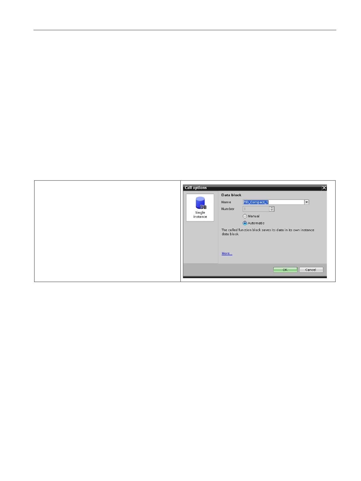
When you insert a PID instruction into your user program,
STEP 7 automatically creates a technology object and an
instance DB for the instruction. The instance DB contains
all of the parameters that are used by the PID instruction.
Each PID instruction must have its own unique instance
DB to operate properly.
After inserting the PID instruction and creating the tech-
nology object and instance DB, you configure the parame-
ters for the technology object (Page 222).
193
PID is easy
8.1 Inserting the PID instruction and technology object
Table 8- 2
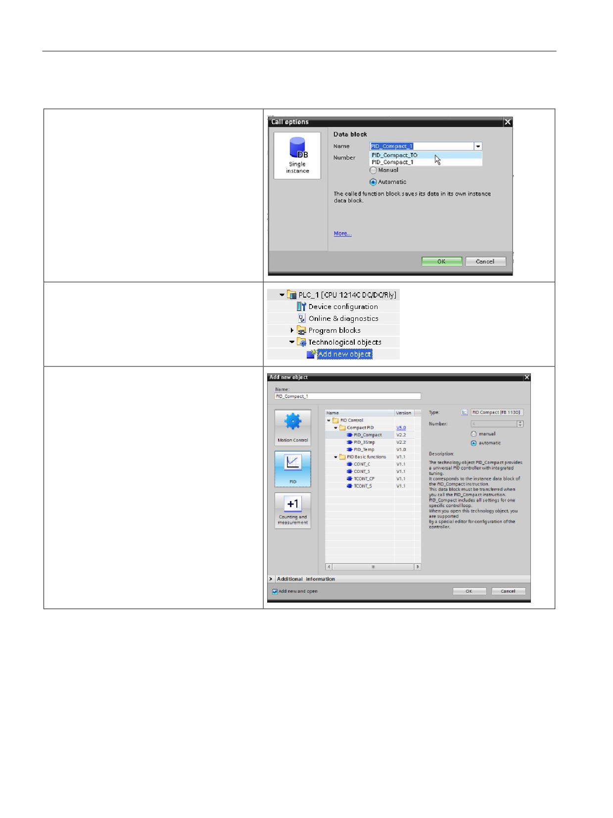
(Optional) Creating a technology object from the project navigator
You can also create technology objects for your
project before inserting the PID instruction. By
creating the technology object before inserting a
PID instruction into your user program, you can
then select the technology object when you insert
the PID instruction.
To create a technology object, double-click the
"Add new object" icon in the project navigator.
Click the "Control" icon and select the technology
object for the type of PID controller (PID_Compact
or PID_3Step). You can create an optional name
for the technology object.
Click "OK" to create the technology object.
194
PID is easy
8.2 PID_Compact instruction
8.2
PID_Compact instruction
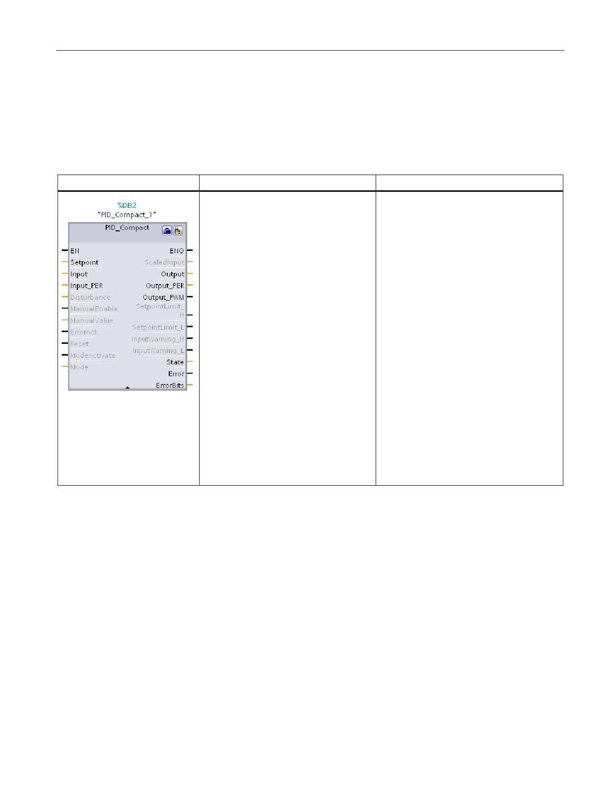
The PID_Compact instruction provides a universal PID controller with integrated self-tuning
for automatic and manual mode.
Table 8- 3
PID_Compact instruction
LAD / FBD
SCL
Description
"PID_Compact_1"(
PID_Compact provides a PID controller with
Setpoint:=_real_in_,
self-tuning for automatic and manual mode.
Input:=_real_in_,
PID_Compact is a PID T1 controller with
Input_PER:=_word_in_,
anti-windup and weighting of the P- and D-
component.
Disturbance:=_real_in_,
ManualEnable:=_bool_in_,
ManualValue:=_real_in_,
ErrorAck:=_bool_in_,
Reset:=_bool_in_,
ModeActivate:=_bool_in_,
Mode:=_int_in_,
ScaledInput=>_real_out_,
Output=>_real_out_,
Output_PER=>_word_out_,
Output_PWM=>_bool_out_,
SetpointLimit_H=>_bool_out_,
SetpointLimit_L=>_bool_out_,
InputWarn-
ing_H=>_bool_out_,
InputWarn-
ing_L=>_bool_out_,
State=>_int_out_,
Error=>_bool_out_,
ErrorBits=>_dword_out_);
1
STEP 7 automatically creates the technology object and instance DB when you insert the instruction. The instance DB
contains the parameters of the technology object.
2
In the SCL example, "PID_Compact_1" is the name of the instance DB.
195

PID is easy
8.2 PID_Compact instruction
Table 8- 4
Data types for the parameters
Parameter and type
Data type
Description
Setpoint
IN
Real
Setpoint of the PID controller in automatic mode. (Default value: 0.0)
Input
IN
Real
A tag of the user program is used as the source of the process value.
(Default value: 0.0)
If you are using the Input parameter, you must set Con-
fig.InputPerOn = FALSE.
Input_PER
IN
Word
An Analog input is used as the source of the process value. (Default
value: W#16#0)
If you are using the Input_PER parameter, you must set Con-
fig.InputPerOn = TRUE.
Disturbance
IN
Real
Disturbance variable or pre-control value
ManualEnable
IN
Bool
Enables or disables the manual operation mode. (Default value:
FALSE):
• A FALSE to TRUE edge activates "manual mode", while State = 4,
Mode remains unchanged.
As long as ManualEnable = TRUE, you cannot change the operat-
ing mode using a rising edge at ModeActivate or use the commis-
sioning dialog.
• A TRUE to FALSE edge activates the operating mode that is as-
signed by Mode.
Note: We recommend that you change the operating mode using
ModeActivate only.
ManualValue
IN
Real
Output value for manual operation. (Default value: 0.0)
You can use values from Config.OutputLowerLimit to Con-
fig.OutputUpperLimit.
ErrorAck
IN
Bool
Resets the ErrorBits and warning outputs. FALSE to TRUE edge
Reset
IN
Bool
Restarts the controller. (Default value: FALSE):
• FALSE to TRUE edge:
- Switches to "inactive" mode
- Resets the ErrorBits and warning outputs
- Clears Integral action
- Maintains PID parameters
• As long as Reset = TRUE, PID_Compact remains in "Inactive"
mode (State = 0).
• TRUE to FALSE edge:
- PID_Compact switches to the operating mode that is saved in
the Mode parameter.
ModeActivate
IN
Bool
The PID_Compact switches to the operating mode that is saved in the
Mode parameter. FALSE to TRUE edge:
Mode
IN
Int
The desired PID mode; Activated on the leading edge of the Mode
Activate input.
ScaledInput
OUT
Real
Scaled process value. (Default value: 0.0)
Output1
OUT
Real
Output value in REAL format. (Default value: 0.0)
Output_PER1
OUT
Word
Analog output value. (Default value: W#16#0)
196

PID is easy
8.2 PID_Compact instruction
Parameter and type
Data type
Description
Output_PWM1
OUT
Bool
Output value for pulse width modulation. (Default value: FALSE)
On and Off times form the output value.
SetpointLimit_H
OUT
Bool
Setpoint high limit. (Default value: FALSE)
If SetpointLimit_H = TRUE, the absolute setpoint upper limit is reached
(Setpoint ≥ Config.SetpointUpperLimit).
The setpoint is limited to Config.SetpointUpperLimit.
SetpointLimit_L
OUT
Bool
Setpoint low limit. (Default value: FALSE)
If SetpointLimit_L = TRUE, the absolute setpoint lower limit is reached
(Setpoint ≤ Config.SetpointLowerLimit).
The setpoint is limited to Config.SetpointLowerLimit.
InputWarning_H
OUT
Bool
If InputWarning_H = TRUE, the process value has reached or exceed-
ed the warning high limit. (Default value: FALSE)
InputWarning_L
OUT
Bool
If InputWarning_L = TRUE, the process value has reached or fallen
below the warning low limit. (Default value: FALSE)
State
OUT
Int
Current operating mode of the PID controller. (Default value: 0)
You can change the operating mode using the Mode input parameter
and a rising edge at ModeActivate:
• State = 0: Inactive
• State = 1: Pre-tuning
• State = 2: Manual fine tuning
• State = 3: Automatic mode
• State = 4: Manual mode
• State = 5: Substitute output value with error monitoring
Error
OUT
Bool
If Error = TRUE, at least one error message is pending in this cycle.
(Default value: FALSE)
Note: The Error parameter in V1.x PID was the ErrorBits field that con-
tained the error codes. It is now a Boolean flag indicating that an error
has occurred.
ErrorBits
OUT
DWord
The PID_Compact instruction ErrorBits parameters table (Page 199)
defines the error messages that are pending. (Default value:
DW#16#0000 (no error)). ErrorBits is retentive and is reset upon a
rising edge at Reset or ErrorAck.
Note: In V1.x, the ErrorBits parameter was defined as the Error param-
eter and did not exist.
1
You can use the outputs of the Output, Output_PER, and Output_PWM parameters in parallel.
197
PID is easy
8.2 PID_Compact instruction
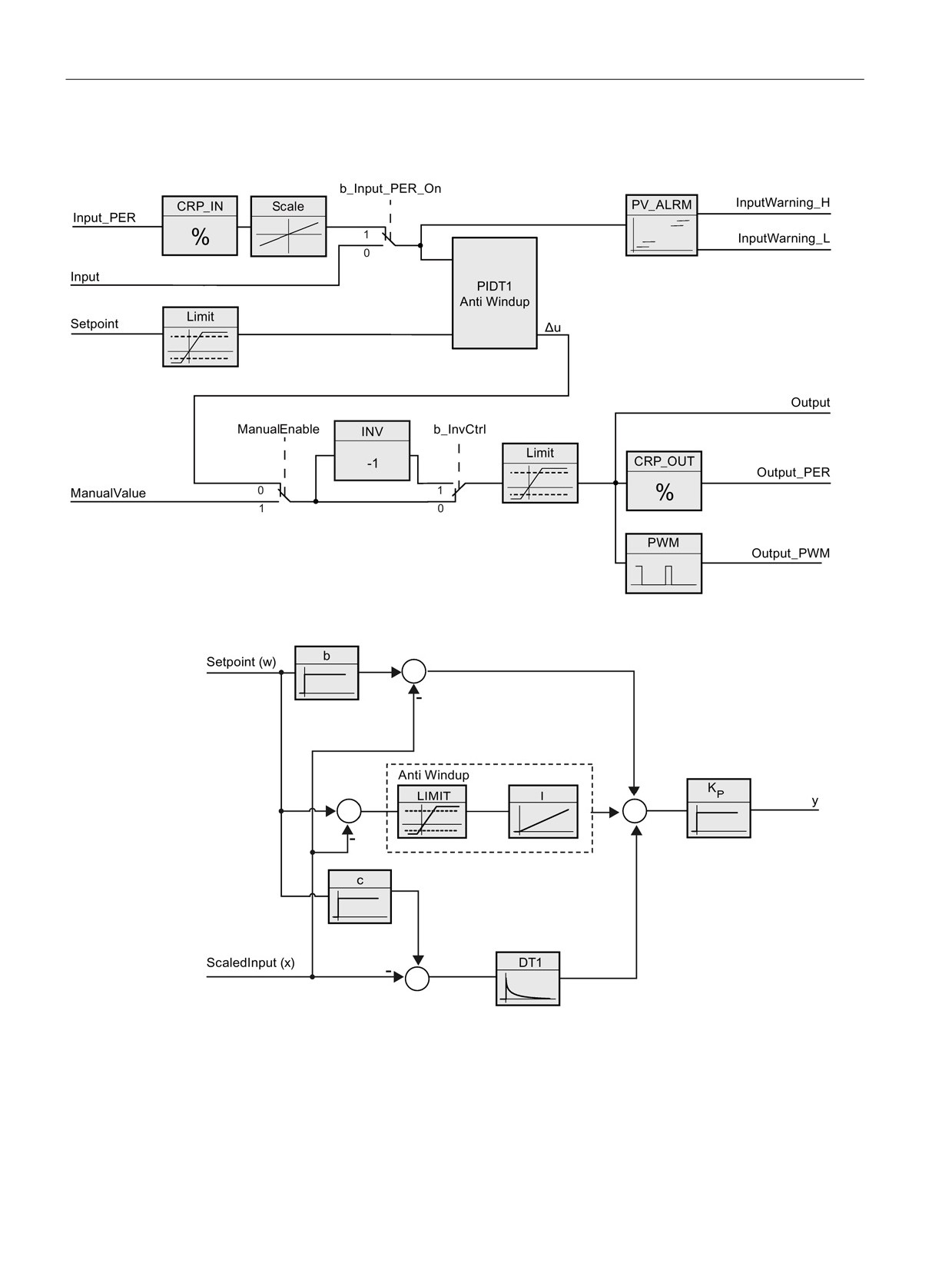
Operation of the PID_Compact controller
Figure 8-1
Operation of the PID_Compact controller
Figure 8-2
Operation of the PID_Compact controller as a PIDT1 controller with anti-windup
198
PID is easy
8.3 PID_Compact instruction ErrorBit parameters
8.3
PID_Compact instruction ErrorBit parameters
If several errors are pending, the values of the error codes are displayed by means of binary
addition. The display of error code 0003, for example, indicates that the errors 0001 and
0002 are also pending.
Table 8- 5
PID_Compact instruction ErrorBit parameters
ErrorBit (DW#16#...)
Description
0000
No error
0001 1, 2
The Input parameter is outside the process value limits.
Input > Config.InputUpperLimit
Input < Config.InputLowerLimit
0002 2, 3
Invalid value at the Input_PER parameter. Check whether an error is pend-
ing at the analog input.
0004 4
Error during fine tuning. Oscillation of the process value could not be main-
tained.
0008 4
Error at start of pre-tuning. The process value is too close to the setpoint.
Start fine tuning.
0010 4
The setpoint was changed during tuning.
Note: You can set the permitted fluctuation on the setpoint at the Cancel-
TuningLevel tag.
0020
Pre-tuning is not permitted during fine tuning.
Note: If ActivateRecoverMode = TRUE before the error occurred,
PID_Compact remains in fine tuning mode.
0080 4
Error during pre-tuning. Incorrect configuration of output value limits.
Check whether the limits of the output value are configured correctly and
match the control logic.
0100 4
Error during fine tuning resulted in invalid parameters.
0200 2, 3
Invalid value at the Input parameter: Value has an invalid number format.
0400 2, 3
Calculation of the output value failed. Check the PID parameters.
0800 1, 2
Sampling time error: PID_Compact is not called within the sampling time of
the cyclic interrupt OB.
1000 2, 3
Invalid value at the Setpoint parameter: Value has an invalid number format.
10000
Invalid value at the ManualValue parameter: Value has an invalid number
format.
Note: If ActivateRecoverMode = TRUE before the error occurred,
PID_Compact uses SubstituteOutput as the output value. As soon as you
assign a valid value in the ManualValue parameter, PID_Compact uses it as
the output value.
199

PID is easy
8.3 PID_Compact instruction ErrorBit parameters
ErrorBit (DW#16#...)
Description
20000
Invalid value at the SubstituteValue tag: Value has an invalid number for-
mat.
PID_Compact uses the output value low limit as the output value.
Note: If automatic mode was active before the error occurred, Acti-
vateRecoverMode = TRUE, and the error is no longer pending,
PID_Compact switches back to automatic mode.
40000
Invalid value at the Disturbance parameter: Value has an invalid number
format.
Note: If automatic mode was active and ActivateRecoverMode = FALSE
before the error occurred, Disturbance is set to zero. PID_Compact remains
in automatic mode.
Note: If pre-tuning or fine tuning mode was active and ActivateRecoverMode
= TRUE before the error occurred, PID_Compact switches to the operating
mode that is saved in the Mode parameter. If Disturbance in the current
phase has no effect on the output value, tuning is not canceled.
1
Note: If automatic mode was active before the error occurred and ActivateRecoverMode = TRUE,
PID_Compact remains in automatic mode.
2
Note: If pre-tuning or fine tuning mode was active before the error occurred and ActivateRecover-
Mode = TRUE, PID_Compact switches to the operating mode that is saved in the
Mode parameter.
3
Note: If automatic mode was active before the error occurred and ActivateRecoverMode = TRUE,
PID_Compact outputs the configured substitute output value. As soon as the error is no longer
pending, PID_Compact switches back to automatic mode.
4
Note: If ActivateRecoverMode = TRUE before the error occurred, PID_Compact cancels the tuning
and switches to the operating mode that is saved in the Mode parameter.
200
PID is easy
8.4 PID_3Step instruction
8.4
PID_3Step instruction
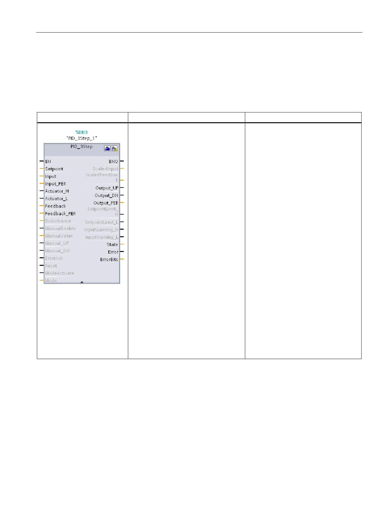
The PID_3Step instruction configures a PID controller with self-tuning capabilities that has
been optimized for motor-controlled valves and actuators.
Table 8- 6
PID_3Step instruction
LAD / FBD
SCL
Description
"PID_3Step_1"(
PID_3Step configures a PID controller with
SetpoInt:=_real_in_,
self-tuning capabilities that has been opti-
Input:=_real_in_,
mized for motor-controlled valves and
ManualValue:=_real_in_,
actuators. It provides two Boolean outputs.
Feedback:=_real_in_,
PID_3Step is a PID T1controller with anti-
InputPer:=_word_in_,
windup and weighting of the P- and D-
FeedbackPer:=_word_in_,
components.
Disturbance:=_real_in_,
ManualEnable:=_bool_in_,
ManualUP:=_bool_in_,
ManualDN:=_bool_in_,
ActuatorH:=_bool_in_,
ActuatorL:=_bool_in_,
ErrorAck:=_bool_in_,
Reset:=_bool_in_,
ModeActivate:=_bool_in_,
Mode:=_int_in_,
ScaledInput=>_real_out_,
ScaledFeedback=>_real_out_,
ErrorBits=>_dword_out_,
OutputPer=>_word_out_,
State=>_int_out_,
OutputUP=>_bool_out_,
OutputDN=>_bool_out_,
SetpoIntLimitH=>_bool_out_,
SetpoIntLimitL=>_bool_out_,
InputWarningH=>_bool_out_,
InputWarningL=>_bool_out_,
Error=>_bool_out_,
ErrorBits=>_dword_out_);
1
STEP 7 automatically creates the technology object and instance DB when you insert the instruction. The instance DB
contains the parameters of the technology object.
2
In the SCL example, "PID_3Step_1" is the name of the instance DB.
201

PID is easy
8.4 PID_3Step instruction
Table 8- 7
Data types for the parameters
Parameter and type
Data type
Description
Setpoint
IN
Real
Setpoint of the PID controller in automatic mode. (Default value: 0.0)
Input
IN
Real
A tag of the user program is used as the source of the process value.
(Default value: 0.0)
If you are using the Input parameter, you must set Con-
fig.InputPerOn = FALSE.
Input_PER
IN
Word
An Analog input is used as the source of the process value. (Default
value: W#16#0)
If you are using the Input_PER parameter, you must set Con-
fig.InputPerOn = TRUE.
Actuator_H
IN
Bool
Digital position feedback of the valve for the high end stop
If Actuator_H = TRUE, the valve is at the high end stop and is no longer
moved in this direction. (Default value: FALSE)
Actuator_L
IN
Bool
Digital position feedback of the valve for the low end stop
If Actuator_L = TRUE, the valve is at the low end stop and is no longer
moved in this direction. (Default value: FALSE)
Feedback
IN
Real
Position feedback of the valve. (Default value: 0.0)
If you are using the Feedback parameter, you must set Con-
fig.FeedbackPerOn = FALSE.
Feedback_PER
IN
Int
Analog feedback of the valve position. (Default value: W#16#0)
If you are using the Feedback_PER parameter, you must set Con-
fig.FeedbackPerOn = TRUE. Feedback_PER is scaled, based upon the
following tags:
• Config.FeedbackScaling.LowerPointIn
• Config.FeedbackScaling.UpperPointIn
• Config.FeedbackScaling.LowerPointOut
• Config.FeedbackScaling.UpperPointOut
Disturbance
IN
Real
Disturbance variable or pre-control value
ManualEnable
IN
Bool
Enables or disables the manual operation mode. (Default value:
FALSE):
• A FALSE to TRUE edge activates "manual mode", while State = 4,
Mode remains unchanged.
As long as ManualEnable = TRUE, you cannot change the operat-
ing mode using a rising edge at ModeActivate or use the commis-
sioning dialog.
• A TRUE to FALSE edge activates the operating mode that is as-
signed by Mode.
Note: We recommend that you change the operating mode using
ModeActivate only.
ManualValue
IN
Real
Process value for manual operation. (Default value: 0.0)
In manual mode, you specify the absolute position of the valve. Manu-
alValue is evaluated only if you are using OutputPer, or if position feed-
back is available.
202

PID is easy
8.4 PID_3Step instruction
Parameter and type
Data type
Description
ManualUP
IN
Bool
• Manual_UP = TRUE:
- The valve is opened even if you use Output_PER or a position
feedback. The valve is no longer moved if the high end stop has
been reached.
- See also Config.VirtualActuatorLimit
• Manual_UP = FALSE:
- If you use Output_PER or a position feedback, the valve is
moved to ManualValue. Otherwise, the valve is no longer
moved.
Note: If Manual_UP and Manual_DN are set to TRUE simultaneously,
the valve is not moved.
ManualDN
IN
Bool
• Manual_DN = TRUE:
- The valve is opened even if you use Output_PER or a position
feedback. The valve is no longer moved if the high end stop has
been reached.
- See also Config.VirtualActuatorLimit
• Manual_DN = FALSE:
- If you use Output_PER or a position feedback, the valve is
moved to ManualValue. Otherwise, the valve is no longer
moved.
ErrorAck
IN
Bool
Resets the ErrorBits and warning outputs. FALSE to TRUE edge
Reset
IN
Bool
Restarts the controller. (Default value: FALSE):
• FALSE to TRUE edge:
- Switches to "inactive" mode
- Resets the ErrorBits and warning outputs
- Clears Integral action
- Maintains PID parameters
• As long as Reset = TRUE, PID_3Step remains in "Inactive" mode
(State = 0).
• TRUE to FALSE edge:
- PID_3Step switches to the operating mode that is saved in the
Mode parameter.
ModeActivate
IN
Bool
The PID_3Step switches to the mode that is saved in the Mode param-
eter. FALSE to TRUE edge:
Mode
IN
Int
The desired PID mode; Activated on the leading edge of the Mode
Activate input.
ScaledInput
OUT
Real
Scaled process value
ScaledFeedback
OUT
Real
Scaled valve position feedback
Note: For an actuator without position feedback, the position of the
actuator indicated by ScaledFeedback is very imprecise. ScaledFeed-
back can only be used for rough estimation of the current position in
this case.
Output_UP
OUT
Bool
Digital output value for opening the valve. (Default value: FALSE)
If Config.OutputPerOn = FALSE, the parameter Output_UP is used.
203

PID is easy
8.4 PID_3Step instruction
Parameter and type
Data type
Description
Output_DN
OUT
Bool
Digital output value for closing the valve. (Default value: FALSE)
If Config.OutputPerOn = FALSE, the parameter Output_DN is used.
Output_PER
OUT
Word
Analog output value.
If Config.OutputPerOn = TRUE, the parameter Output_PER is used.
SetpointLimitH
OUT
Bool
Setpoint high limit. (Default value: FALSE)
If SetpointLimitH = TRUE, the absolute upper limit of the setpoint is
reached (Setpoint ≥ Config.SetpointUpperLimit).
Note: The setpoint is limited to (Setpoint ≥ Config.SetpointUpperLimit).
SetpointLimitL
OUT
Bool
Setpoint low limit. (Default value: FALSE)
If SetpointLimitL = TRUE, the absolute lower limit of the setpoint is
reached (Setpoint ≥ Config.SetpointLowerLimit).
Note: The setpoint is limited to (Setpoint ≥ Config.SetpointLowerLimit).
InputWarningH
OUT
Bool
If InputWarningH = TRUE, the input value has reached or exceeded the
warning high limit. (Default value: FALSE)
InputWarningL
OUT
Bool
If InputWarningL = TRUE, the input value has reached or exceeded the
warning low limit. (Default value: FALSE)
State
OUT
Int
Current operating mode of the PID controller. (Default value: 0)
You can change the operating mode using the Mode input parameter
and a rising edge at ModeActivate:
• State = 0: Inactive
• State = 1: Pre-tuning
• State = 2: Manual fine tuning
• State = 3: Automatic mode
• State = 4: Manual mode
• State = 5: Substitute output value approach
• State = 6: Transition time measurement
• State = 7: Error monitoring
• State = 8: Substitute output value approach with error monitoring\
• State = 10: Manual mode without end stop signals
Error
OUT
Bool
If Error = TRUE, at least one error message is pending. (Default value:
FALSE)
Note: The Error parameter in V1.x PID was the ErrorBits field that con-
tained the error codes. It is now a Boolean flag indicating that an error
has occurred.
ErrorBits
OUT
DWord
The PID_3Step instruction ErrorBits parameters table (Page 208) de-
fines the error messages that are pending. (Default value:
DW#16#0000 (no error)). ErrorBits is retentive and is reset upon a
rising edge at Reset or ErrorAck.
Note: In V1.x, the ErrorBits parameter was defined as the Error param-
eter and did not exist.
204
PID is easy
8.4 PID_3Step instruction
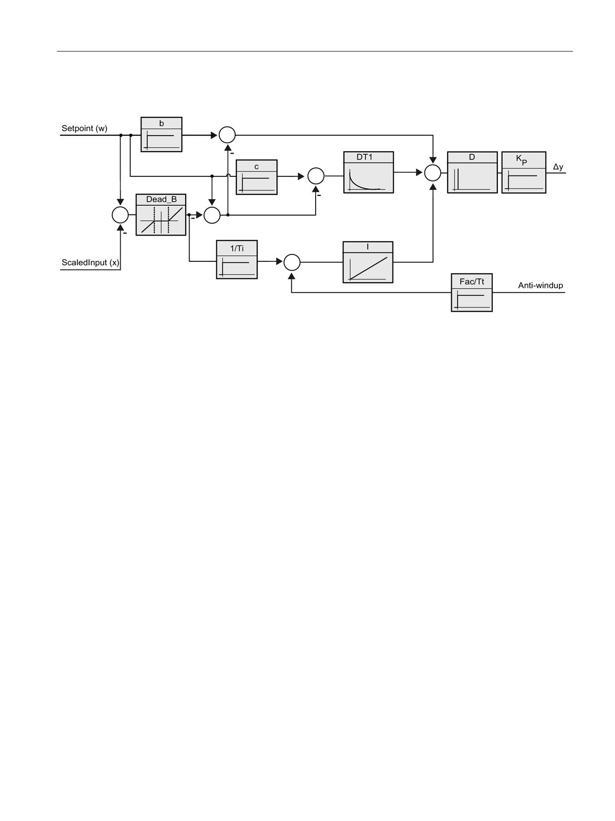
Operation of the PID_3Step controller
Figure 8-3
Operation of the PID_3Step controller as a PID T1 controller with anti-windup
205
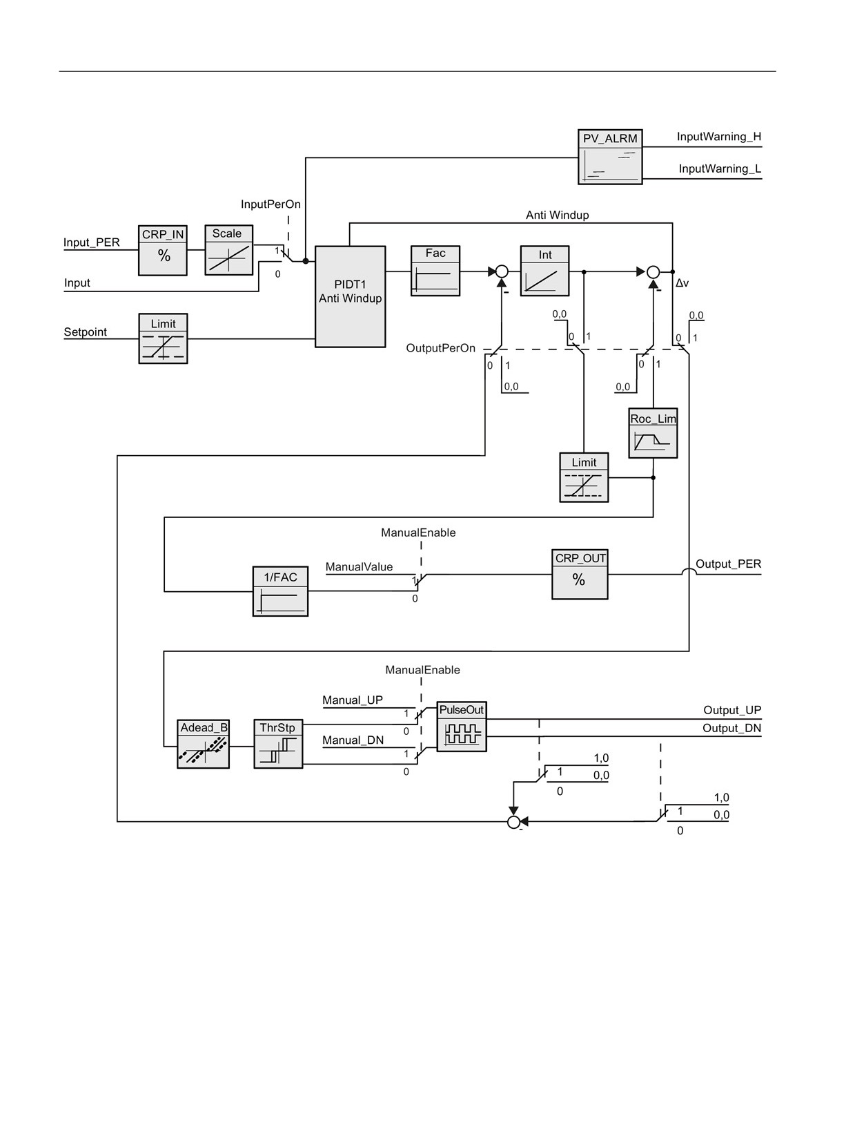
PID is easy
8.4 PID_3Step instruction
Figure 8-4
Operation of the PID_3Step controller without position feedback
206
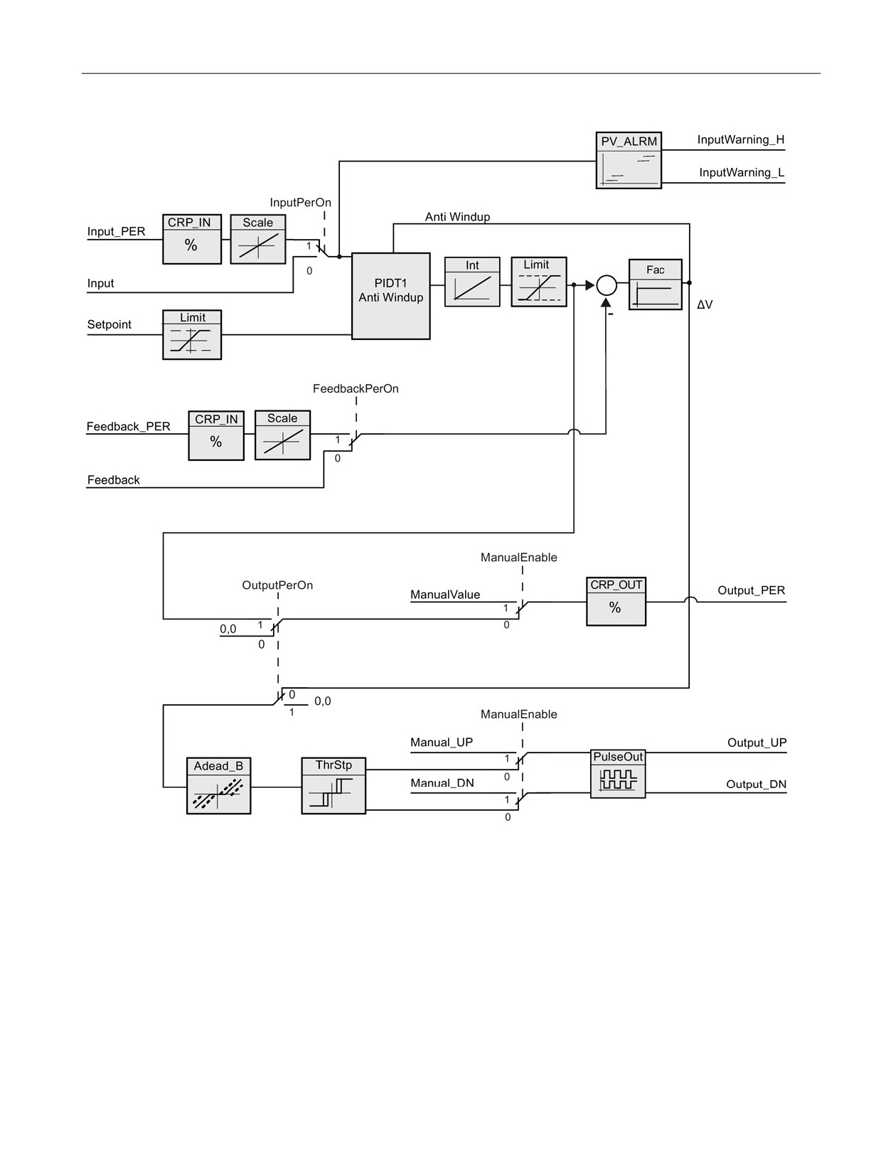
PID is easy
8.4 PID_3Step instruction
Figure 8-5
Operation of the PID_3Step controller with position feedback enabled
207
PID is easy
8.5 PID_3Step instruction ErrorBit parameters
8.5
PID_3Step instruction ErrorBit parameters
If several errors are pending, the values of the error codes are displayed by means of binary
addition. The display of error code 0003, for example, indicates that the errors 0001 and
0002 are also pending.
Table 8- 8
PID_3STEP instruction ErrorBit parameters
ErrorBit (DW#16#...)
Description
0000
No error
0001 1, 2
The Input parameter is outside the process value limits.
Input > Config.InputUpperLimit
Input < Config.InputLowerLimit
0002 2, 3
Invalid value at the Input_PER parameter. Check whether an error is pend-
ing at the analog input.
0004 4
Error during fine tuning. Oscillation of the process value could not be main-
tained.
0010 4
The setpoint was changed during tuning.
Note: You can set the permitted fluctuation on the setpoint at the Cancel-
TuningLevel tag.
0020
Pre-tuning is not permitted during fine tuning.
Note: If ActivateRecoverMode = TRUE before the error occurred, PID_3Step
remains in fine tuning mode.
0080 4
Error during pre-tuning. Incorrect configuration of output value limits.
Check whether the limits of the output value are configured correctly and
match the control logic.
0100 4
Error during fine tuning resulted in invalid parameters.
0200 2, 3
Invalid value at the Input parameter: Value has an invalid number format.
0400 2, 3
Calculating the output value failed. Check the PID parameters.
0800 1, 2
Sampling time error: PID_3Step is not called within the sampling time of the
cyclic interrupt OB.
1000 2, 3
Invalid value at the Setpoint parameter: Value has an invalid number format.
2000 1, 2, 5
Invalid value at the Feedback_PER parameter.
Check whether an error is pending at the analog input.
4000 1, 2, 5
Invalid value at the Feedback parameter: Value has an invalid number for-
mat.
8000 1, 2
Error during digital position feedback. Actuator_H = TRUE and Actuator_L =
TRUE.
The actuator cannot be moved to the substitute output value and remains in
its current position. Manual mode is not possible in this state.
In order to move the actuator from this state, you must deactivate the "Actu-
ator end stop" (Config.ActuatorEndStopOn = FALSE) or switch to manual
mode without end stop signals (Mode = 10).
208

PID is easy
8.5 PID_3Step instruction ErrorBit parameters
ErrorBit (DW#16#...)
Description
10000
Invalid value at the ManualValue parameter: Value has an invalid number
format.
The actuator cannot be moved to the manual value and remains in its cur-
rent position.
Assign a valid value in ManualValue or move the actuator in manual mode
with Manual_UP and Manual_DN.
20000
Invalid value at the SavePosition tag: Value has an invalid number format.
The actuator cannot be moved to the substitute output value and remains in
its current position.
40000
Invalid value at the Disturbance parameter: Value has an invalid number
format.
Note: If automatic mode was active and ActivateRecoverMode = FALSE
before the error occurred, Disturbance is set to zero. PID_3Step remains in
automatic mode.
Note: If pre-tuning or fine tuning mode was active and ActivateRecoverMode
= TRUE before the error occurred, PID_3Step switches to the operating
mode that is saved in the Mode parameter. If Disturbance in the current
phase has no effect on the output value, tuning is not canceled.
The error has no effect during transition time measurement.
1
Note: If automatic mode was active before the error occurred and ActivateRecoverMode = TRUE,
PID_3Step remains in automatic mode.
2
Note: If pre-tuning, fine tuning, or transition time measurement mode were active and Acti-
vateRecoverMode = TRUE before the error occurred, PID_3Step switches to the operating mode
that is saved in the Mode parameter.
3
Note: If automatic mode was active before the error occurred and ActivateRecoverMode = TRUE,
PID_3Step switches to "Approach substitute output value with error monitoring" or "Error monitor-
ing" mode. As soon as the error is no longer pending, PID_3Step switches back to automatic
mode.
4
Note: If ActivateRecoverMode = TRUE before the error occurred, PID_3Step cancels the tuning
and switches to the operating mode that is saved in the Mode parameter.
5
The actuator cannot be moved to the substitute output value and remains in its current position. In
manual mode, you can change the position of the actuator only with Manual_UP and Manual_DN,
and not with ManualValue.
209
PID is easy
8.6 PID_Temp instruction
8.6
PID_Temp instruction
8.6.1
Overview
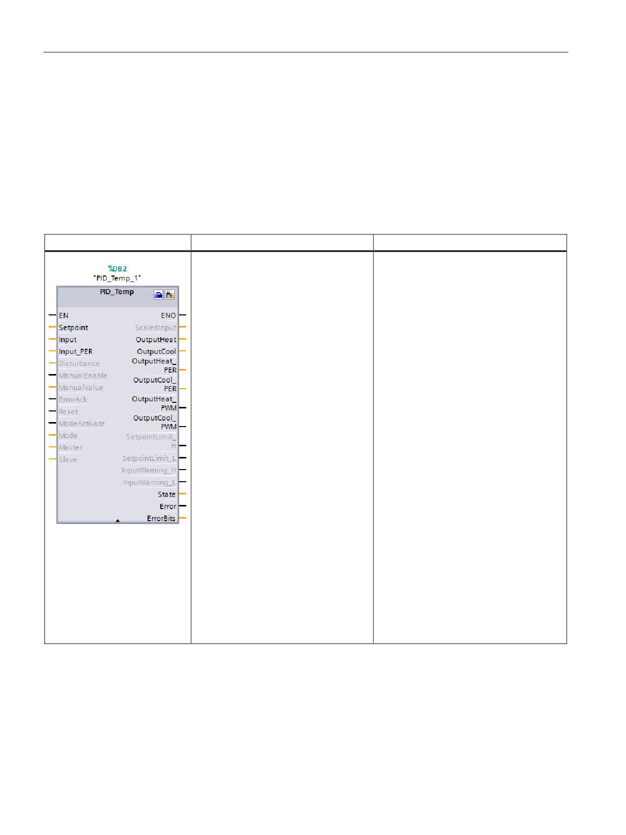
The PID_Temp instruction provides a universal PID controller that allows handling of the
specific requirements of temperature control.
Table 8- 9
PID_Temp instruction
LAD / FBD
SCL
Description
"PID_Temp_1"(
PID_Temp provides these capabilities:
Setpoint:=_real_in_,
•
Heating and cooling of the process with
Input:=_real_in_,
different actuators
Input_PER:=_int_in_,
•
Integrated autotuning to handle temper-
Disturbance:=_real_in_,
ature processes
ManualEnable:=_bool_in_,
ManualValue:=_real_in_,
•
Cascading to process more than one
ErrorAck:=_bool_in_,
temperature that depends on the same
Reset:=_bool_in_,
actuator
ModeActivate:=_bool_in_,
Mode:=_int_in_,
Master:=_dword_in
Save:=_dword_in
ScaledInput=>_real_out_,
OutputHeat=>_real_out_,
OutputCool=>_real_out_,
OutputHeat_PER=>_int_out_,
OutputCool_PER=>_int_out_,
Out-
putHeat_PWM=>_bool_out_,
Out-
putCool_PWM=>_bool_out_,
SetpointLimit_H=>_bool_out_,
SetpointLimit_L=>_bool_out_,
InputWarn-
ing_H=>_bool_out_,
InputWarn-
ing_L=>_bool_out_,
State=>_int_out_,
Error=>_bool_out_,
ErrorBits=>_dword_out_);
1
STEP 7 automatically creates the technology object and instance DB when you insert the instruction. The instance DB
contains the parameters of the technology object.
2
In the SCL example, "PID_Temp_1" is the name of the instance DB.
210

PID is easy
8.6 PID_Temp instruction
Table 8- 10 Data types for the parameters
Parameter and type
Data type
Description
Setpoint
IN
Real
Setpoint of the PID controller in automatic mode. (Default value: 0.0)
Input
IN
Real
A tag of the user program is used as the source of the process value.
(Default value: 0.0)
If you are using the Input parameter, you must set Con-
fig.InputPerOn = FALSE.
Input_PER
IN
Int
An Analog input is used as the source of the process value. (Default
value: 0)
If you are using the Input_PER parameter, you must set Con-
fig.InputPerOn = TRUE.
Disturbance
IN
Real
Disturbance variable or pre-control value
ManualEnable
IN
Bool
Enables or disables the manual operation mode. (Default value:
FALSE):
• A FALSE to TRUE edge activates Manual mode, while State = 4,
Mode remains unchanged.
As long as ManualEnable = TRUE, you cannot change the operat-
ing mode using a rising edge at ModeActivate or use the commis-
sioning dialog.
• A TRUE to FALSE edge activates the operating mode that is as-
signed by Mode.
Note: We recommend that you change the operating mode using
ModeActivate only.
ManualValue
IN
Real
Output value for manual operation. (Default value: 0.0)
You can use values from Config.OutputLowerLimit to Con-
fig.OutputUpperLimit.
ErrorAck
IN
Bool
Resets the ErrorBits and warning outputs with a FALSE to TRUE edge.
(Default value: FALSE)
Reset
IN
Bool
Restarts the controller. (Default value: FALSE):
• FALSE to TRUE edge:
- Switches to "inactive" mode
- Resets the ErrorBits and warning outputs
- Clears Integral action
- Maintains PID parameters
• As long as Reset = TRUE, PID_Temp remains in Inactive mode
(State = 0).
• TRUE to FALSE edge:
- PID_Temp switches to the operating mode that is saved in the
Mode parameter.
ModeActivate
IN
Bool
The PID_Temp switches to the operating mode that is saved in the
Mode parameter with a FALSE to TRUE edge. (Default value: FALSE)
211

PID is easy
8.6 PID_Temp instruction
Parameter and type
Data type
Description
Mode
IN/OUT
Int
Activated on the leading edge of the Mode Activate input.
Operating mode selection (Default value: 0.0):
• Mode = 0: Inactive
• Mode = 1: Pretuning
• Mode = 2: Fine tuning
• Mode = 3: Automatic mode
• Mode = 4: Manual mode
“Substitute output value with error monitoring” (State = 5). This cannot
be activated by the user; it is only an automatic error reaction.
Master
IN/OUT
DWord
Cascade connection to master (AntiWindUp and tuning conditions).
(Default value: DW#16#0000)
Slave
IN/OUT
DWord
• Bits 0 - 15: Not used in PID_Temp instruction
• Bits 16 - 23: Limit counter: A slave increments this value if it reach-
es its limitation. The number of slaves in limitation is processed for
Anti-Windup-functionality (Refer to the Con-
fig.Cascade.AntiWindUpMode parameter.
• Bit 24: IsAutomatic: This bit is set to "1" if all slaves of this controller
are in Automatic mode and are processed to check conditions for
tuning in a cascade. This bit is identical to the AllSlaveAutomat-
icState parameter.
• Bit 25: "IsReplacement-Setpoint": This bit is set to "1" if a slave of
this controller has the "Replacement Setpoint" activated and is pro-
cessed to check conditions for tuning in a cascade. The inverted
value is stored in the NoSlaveReplacementSetpoint parameter.
ScaledInput
OUT
Real
Scaled process value. (Default value: 0.0)
OutputHeat1
OUT
Real
Output value for heating in REAL format. (Default value: 0.0)
This output value is calculated, independent from the output selection,
using the Config.Output.Heat.Select parameter.
OutputCool1
OUT
Real
Output value for cooling in REAL format. (Default value: 0.0)
This output value is calculated, independent from the output selection,
using the Config.Output.Cool.Select parameter.
OutputHeat_PER
1
OUT
Int
Output value for heating in peripheral format (Default value: 0)
This output value is only calculated if selected using the Con-
fig.Output.Heat.Select = 2 parameter. If not selected, this output is
always "0".
OutputCool_PER1
OUT
Int
Output value for cooling in peripheral format (Default value: 0)
This output value is only calculated if selected using the Con-
fig.Output.Cool.Select = 2 parameter. If not selected, this output is
always "0".
OutputHeat_PWM1
OUT
Bool
Pulse-width-modulated output value for heating. (Default value: FALSE)
This output value is only calculated if selected using the Con-
fig.Output.Heat.Select = 1 (default value) parameter. If not selected,
this output is always FALSE.
212

PID is easy
8.6 PID_Temp instruction
Parameter and type
Data type
Description
OutputCool_PWM1
OUT
Bool
Pulse-width-modulated output value for cooling. (Default value: FALSE)
This output value is only calculated if selected using the Con-
fig.Output.Cool.Select = 1 (default value) parameter. If not selected, this
output is always FALSE.
SetpointLimit_H
OUT
Bool
Setpoint high limit. (Default value: FALSE)
If SetpointLimit_H = TRUE, the absolute setpoint upper limit is reached
(Setpoint ≥ Config.SetpointUpperLimit).
The setpoint is limited to Config.SetpointUpperLimit.
SetpointLimit_L
OUT
Bool
Setpoint low limit. (Default value: FALSE)
If SetpointLimit_L = TRUE, the absolute setpoint lower limit is reached
(Setpoint ≤ Config.SetpointLowerLimit).
The setpoint is limited to Config.SetpointLowerLimit.
InputWarning_H
OUT
Bool
If InputWarning_H = TRUE, the process value has reached or exceed-
ed the warning high limit. (Default value: FALSE)
InputWarning_L
OUT
Bool
If InputWarning_L = TRUE, the process value has reached or fallen
below the warning low limit. (Default value: FALSE)
State
OUT
Int
Current operating mode of the PID controller. (Default value: 0)
You can change the operating mode using the Mode input parameter
and a rising edge at ModeActivate:
• State = 0: Inactive
• State = 1: Pre-tuning
• State = 2: Fine tuning
• State = 3: Automatic mode
• State = 4: Manual mode
• State = 5: Substitute output value with error monitoring
Error
OUT
Bool
If Error = TRUE, at least one error message is pending in this cycle.
(Default value: FALSE)
Note: The Error parameter in V1.x PID was the ErrorBits field that con-
tained the error codes. It is now a Boolean flag indicating that an error
has occurred.
ErrorBits
OUT
DWord
The PID_Temp instruction, ErrorBits parameters table
(Page 220)defines the error messages that are pending. (Default value:
DW#16#0000 (no error)). ErrorBits is retentive and is reset upon a
rising edge at Reset or ErrorAck.
Note: In V1.x, the ErrorBits parameter was defined as the Error pa-
rameter and did not exist.
Warning
OUT
DWord
The PID_Temp instruction, Warning parameters table defines the user-
relevant warning messages that are pending. (Default value:
DW#16#0000 (no warning)).
WarningInternal
OUT
DWord
The PID_Temp instruction, WarningInternal parameters table defines
the warning internal messages that are pending (includes all warnings).
(Default value: DW#16#0000 (no warning internal)).
1
You can use the outputs of the Output, Output_PER, and Output_PWM parameters in parallel.
213
PID is easy
8.6 PID_Temp instruction
8.6.2
Operation of the PID_Temp controller
Selecting heating and/or cooling control
You must first select if you need a cooling device in addition to the heating output at
parameter "ActivateCooling". Afterwards, you must define if you want to use two PID-
parameter-sets (advanced mode) or only one PID-parameter-set with an additional
heating/cooling-factor at parameter "AdvancedCooling".
Using CoolFactor
In case you want to apply a heating/cooling-factor, you must define the value manually. You
have to identify the value from the technical data of your application (ratio of proportional
gain of the actuators (for example, the ratio of maximum heating- and cooling-power of the
actuators) and assign it to parameter "CoolFactor". A heating/cooling-factor of 2.0 means
that the heating device is two times more effective than the cooling device. If you use cooling
factor, PID_Temp calculates the output signal and, depending on its sign, multiply the output
signal with the heating/cooling-factor (when sign is negative) or not (when sign is positive).
Using two PID-parameter-sets
Different PID-parameter-sets for heating and cooling can be automatically detected during
commissioning. You can expect a better control performance compared to heating/cooling-
factor because, in addition to different proportional gains, you can consider different delay
times with two parameters-sets. However, the disadvantage is that this can take more time
for the tuning process. If PID-parameter switchover is activated (Config.AdvancedCooling =
TRUE), the PID_Temp controller detects in "Automatic mode" (controlling is active) if heating
or cooling is necessary at that time and uses PID-parameter-sets for control.
ControlZone
With the PID_Temp controller, you can define a control zone for each parameter-set at
parameter "ControlZone". If the control deviation (setpoint - input) is within the control zone,
PID_Temp uses the PID-algorithm to calculate the output signals. However, if the control
deviation leaves the defined range, the output is set to the maximum heating or maximum
cooling output value (cooling output activated) / minimum heating output value (cooling
output deactivated). You can use this functionality to reach the desired setpoint faster,
especially for initial heating-up of slow temperature processes.
DeadZone
In the "DeadZone" parameter, you can define a width of control deviation for heating and
cooling that is neglected by the PID-algorithm. This means a control deviation within this
range is suppressed, and the PID_Temp controller behaves like the setpoint and process
values are identical. Thus, you can reduce unnecessary intervention by the controller around
the setpoint and conserve the actuator. If you want to apply a DeadZone, you must define
the value manually. Auto tuning does not automatically set the DeadZone value. DeadZone
is symmetric (between -Retain.CtrlParams.Heat.DeadZone and
+Retain.CtrlParams.Heat.DeadZone) for heating controllers without cooling or
heating/cooling controllers using CoolFactor. DeadZone can be asymmetric (between -
Retain.CtrlParams.Cool.DeadZone and +Retain.CtrlParams.Heat.DeadZone) for
heating/cooling controllers using two PID-parameter sets.
214
PID is easy
8.6 PID_Temp instruction
PID_Temp controller operations
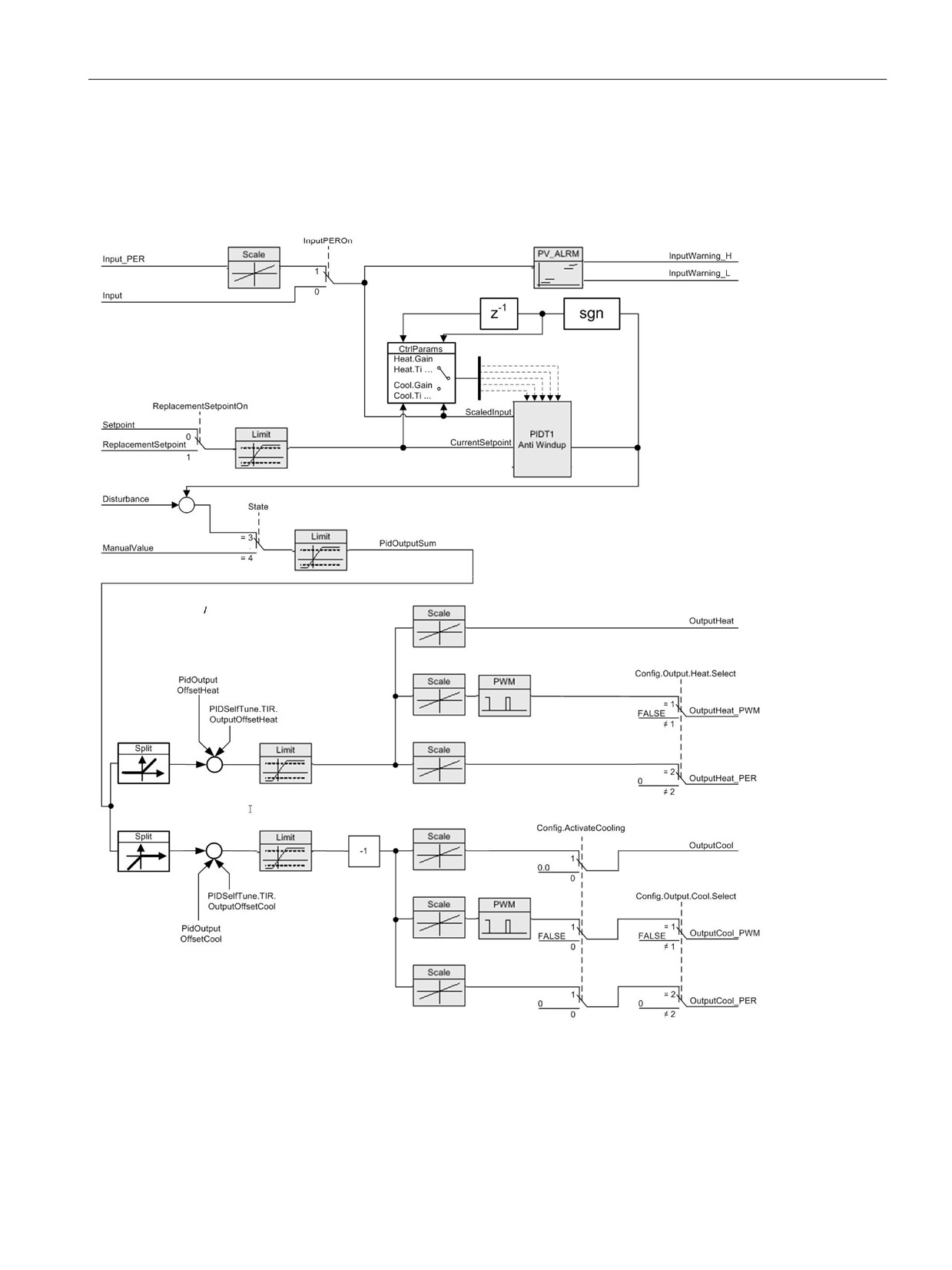
The following block diagrams illustrate the PID_Temp instruction standard and cascade
operations:
Figure 8-6
PID_Temp_Operation_Block_Diagram
215
PID is easy
8.6 PID_Temp instruction
Figure 8-7
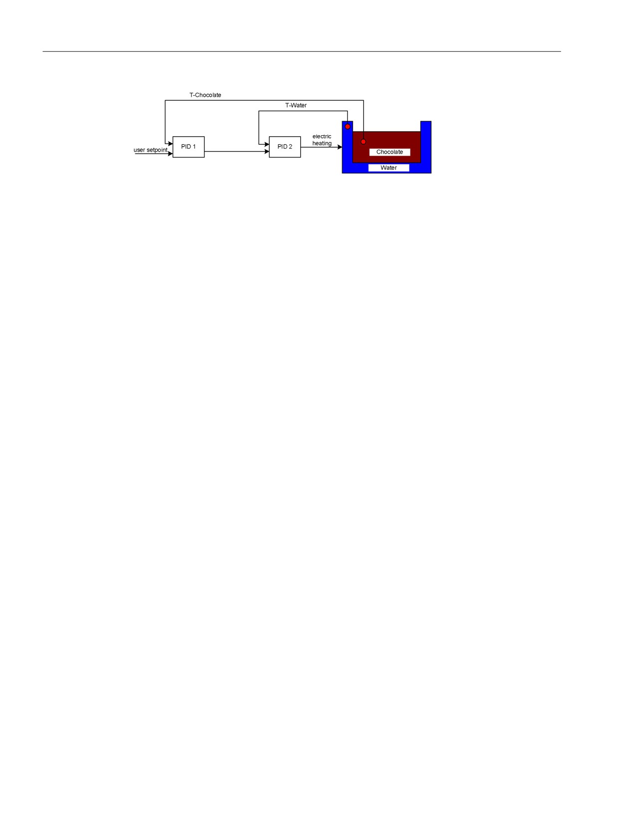
PID_Temp_Cascade_Operation_Block_Diagram
8.6.3
Cascading controllers
You can cascade temperature PID controllers to process more than one temperature that
depend on the same actuator.
Call order
You must call cascaded PID controllers in the same OB cycle. First, you must call the
master, then, the next slave(s) in the control signal flow, and finally on to the last slave in the
cascade. The PID_Temp instruction does not make an automatic check of call order.
216
PID is easy
8.6 PID_Temp instruction
Communication connections
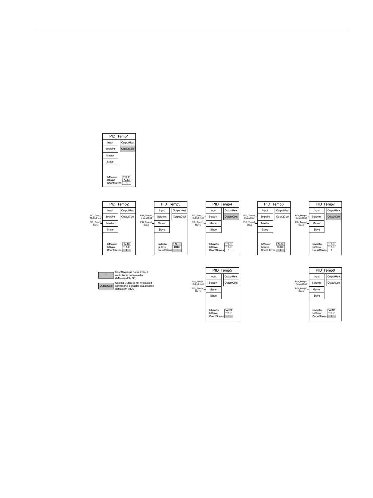
When cascading controllers, you must connect the master and slave so that they can share
information with each other. You must connect a slave’s “Master” IN/OUT parameter to its
master’s “Slave” IN/OUT parameter in the signal flow direction.
This shows a connection of PID_Temp controllers in a cascade with two sub-cascades:
"PID_Temp1" provides the setpoint. The configuration connects the outputs of "PID_Temp2",
"PID_Temp3", "PID_Temp5", "PID_Temp6", and "PID_Temp8" to the process:
Figure 8-8
PID_Temp_Cascading_communication_connection
Replacement setpoint
The PID_Temp instruction provides a second setpoint input at the “ReplacementSetpoint”
parameter that you can activate by setting the parameter “ReplacementSetpointOn” = TRUE.
You can use “ReplacementSetpoint” as your setpoint input during commissioning or tuning of
a slave controller without having to disconnect the output-to-setpoint connection between
master and slave. This connection is necessary for normal operation of the cascade.
In this way, you do not have to change your program and download it if you want to
temporarily separate a slave from its master. You only have to activate the
"ReplacementSetpoint" and deactivate it again when you finish.The setpoint value is
effective for the PID algorithm when you can see the value at the “CurrentSetpoint”
parameter.
217
PID is easy
8.6 PID_Temp instruction
Autotuning
An autotuning for a cascaded master controller must meet these requirements:
● Be commissioned from its inner slave to the first master.
● All slaves of the master have to be in “Automatic mode".
● The output of the master must be the setpoint for the slaves.
PID_Temp instruction will provide the following support for autotuning in the cascade:
● If you start autotuning for a master controller, the master checks to see if all slaves are in
“Automatic mode” and for the deactivation of the Replacement-Setpoint-functionality for
all slaves (“ReplacementSetpointOn” = FALSE). If you do not meet these conditions, you
cannot autotune the master. The master cancels the tuning, goes to “Inactive” mode" (if
“ActivateRecoverMode” = FALSE), or back to the mode stored in the “Mode” parameter (if
“ActivateRecoverMode” = TRUE). The master displays the error message 200000hex
("Error with master in the cascade. Slaves are not in automatic mode or have a substitute
setpoint enabled and are preventing tuning of the master.").
● When all slaves are in “Automatic mode”, the system sets the parameter
“AllSlaveAutomaticState” = TRUE. You can apply this parameter in your programs or
localize the cause of error 200000hex.
● When the "ReplacementSetpoint" is deactivated for all slaves, the system sets the
parameter “NoSlaveReplacementSetpoint” = TRUE. You can apply this parameter in their
programs or localize the cause of error 200000hex.
When the PID_Temp instruction commissioning dialog is used, you have further support for
cascade tuning (Page 241).
Operation modes and error handling
The PID_Temp controller does not allow switching of the operating mode by its master or
slaves. This means that a master inside the cascade stays in its current mode when a slave
raises an error. This is an advantage if two or more parallel slaves operate with this master
controller; an error in one chain does not shut down the parallel chain.
Similarly, a slave inside the cascade stays in its current operation mode, if its master has an
error. However, further operation of the slave then depends on the configuration of the
master because the slave’s setpoint is the the master’s output. This means that if you
configure the master with “ActivateRecoverMode” = TRUE and an error occurs, the master
outputs the last valid or a substitute output value as setpoint for the slave. If you configure
the master with “ActivateRecoverMode” = FALSE, the master switchs to “Inactive mode" and
sets all outputs to "0.0" so that the slave uses "0.0" as its setpoint.
Because only the slave controllers have direct access to the actuators and these stay in their
operating mode in case of a master error, you can avoid damage to the process. For
example, for plastics processing devices, it is fatal for the slaves to stop working, shut down
the actuators, and allow the plastic to harden inside the device solely because the master
controller had an error.
218

PID is easy
8.6 PID_Temp instruction
Anti-windup
A slave in a cascade gets its setpoint from the output of his master. If the slave reaches its
own output limits while the master still sees a control deviation (setpoint - input), the master
freezes or reduces its integration contribution to prevent a so-called "WindUp". In case of a
"WindUp", the master increases its integration contribution to a very large value and must
reduce it first, before the controller can again have a normal reaction. Such a "WindUp"
affects the dynamic of the control negatively. The PID_Temp provides ways to prevent this
effect in a cascade by configuring the parameter “Config.Cascade.AntiWindUpMode” of the
master controller:
Value
Description
0
Deactivates Anti-Windup functionality.
1
Reduces the integration contribution of the master controller at the ratio “slaves
in limitation” to “existing slaves” (parameter “CountSlaves”).
2
Freezes the integration contribution of the master as soon as one slave reaches
its limitation. Only relevant if "Config.Cascade.IsMaster" = TRUE.
219
PID is easy
8.7 PID_Temp instruction ErrorBit parameters
8.7
PID_Temp instruction ErrorBit parameters
If the PID controller has several warnings pending, it displays the values of the error codes
by means of binary addition. The display of error code 0003, for example, indicates that the
errors 0001 and 0002 are pending.
Table 8- 11 PID_Temp instruction ErrorBit parameters
ErrorBit (DW#16#...)
Description
0000
No error
0001 1, 2
The Input parameter is outside the process value limits.
Input > Config.InputUpperLimit
Input < Config.InputLowerLimit
0002 2, 3
Invalid value at the Input_PER parameter. Check whether an error is pend-
ing at the analog input.
0004 4
Error during fine tuning. Oscillation of the process value could not be main-
tained.
0008 4
Error at start of pre-tuning. The process value is too close to the setpoint.
Start fine tuning.
0010 4
The setpoint was changed during tuning.
Note: You can set the permitted fluctuation on the setpoint at the Cancel-
TuningLevel tag.
0020
Pre-tuning is not permitted during fine tuning.
Note: If ActivateRecoverMode = TRUE before the error occurred,
PID_Temp remains in fine tuning mode.
0040 4
Error during pretuning. The cooling could not reduce the process value.
0080 4
Error during pre-tuning. Incorrect configuration of output value limits.
Check whether the limits of the output value are configured correctly and
match the control logic.
0100 4
Error during fine tuning resulted in invalid parameters.
0200 2, 3
Invalid value at the Input parameter: Value has an invalid number format.
0400 2, 3
Calculation of the output value failed. Check the PID parameters.
0800 1, 2
Sampling time error: PID_Temp is not called within the sampling time of the
cyclic interrupt OB.
1000 2, 3
Invalid value at the Setpoint parameter: Value has an invalid number format.
10000
Invalid value at the ManualValue parameter: Value has an invalid number
format.
Note: If ActivateRecoverMode = TRUE before the error occurred,
PID_Temp uses SubstituteOutput as the output value. As soon as you as-
sign a valid value in the ManualValue parameter, PID_Temp uses it as the
output value.
20000
Invalid value at the SubstituteValue tag: Value has an invalid number for-
mat.
PID_Temp uses the output value low limit as the output value.
Note: If automatic mode was active before the error occurred, Acti-
vateRecoverMode = TRUE, and the error is no longer pending, PID_Temp
switches back to automatic mode.
220

PID is easy
8.7 PID_Temp instruction ErrorBit parameters
ErrorBit (DW#16#...)
Description
40000
Invalid value at the Disturbance parameter: Value has an invalid number
format.
Note: If automatic mode was active and ActivateRecoverMode = FALSE
before the error occurred, Disturbance is set to zero. PID_Temp remains in
automatic mode.
Note: If pre-tuning or fine tuning mode was active and ActivateRecover-
Mode = TRUE before the error occurred, PID_Temp switches to the operat-
ing mode that is saved in the Mode parameter. If Disturbance in the current
phase has no effect on the output value, tuning is not canceled.
200000
Error with master in the cascade. Slaves are not in automatic mode or have
a substitute setpoint enabled, preventing tuning of the master.
400000
The PID controller does not permit pretuning for heating while cooling is
active.
800000
The process value must be close to the setpoint in order to start pretuning
for cooling.
1000000
Error starting tuning. “Heat.EnableTuning” and “Cool.EnableTuning” are not
set or do not match the configuration.
2000000
Pretuning for cooling requires successful pretuning for heating.
4000000
Error starting fine tuning. “Heat.EnableTuning” and “Cool.EnableTuning”
cannot be set at the same time.
8000000
Error during PID parameter calculation resulted in invalid parameters (for
example, negative Gain; the current PID parameters remain unchanged and
tuning has no effect).
1
Note: If automatic mode was active before the error occurred and ActivateRecoverMode = TRUE,
PID_Temp remains in automatic mode.
2
Note: If pre-tuning or fine tuning mode was active before the error occurred and ActivateRecover-
Mode = TRUE, PID_Temp switches to the operating mode that is saved in the Mode parameter.
3
Note: If automatic mode was active before the error occurred and ActivateRecoverMode = TRUE,
PID_Compact outputs the configured substitute output value. As soon as the error is no longer
pending, PID_Temp switches back to automatic mode.
4
Note: If ActivateRecoverMode = TRUE before the error occurred, PID_Temp cancels the tuning
and switches to the operating mode that is saved in the Mode parameter.
221
PID is easy
8.8 Configuring the PID_Compact and PID_3Step controllers
8.8
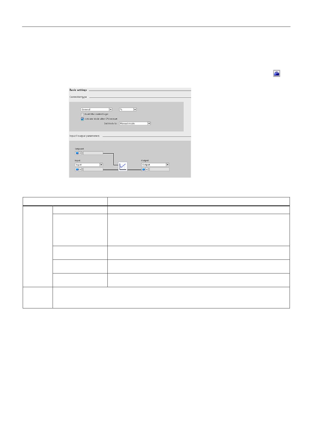
Configuring the PID_Compact and PID_3Step controllers
The parameters of the technology object determine the operation of the PID control-
ler. Use the icon to open the configuration editor.
Table 8- 12 Example configuration settings for the PID_Compact instruction
Settings
Description
Basic
Controller type
Selects the engineering units.
Invert the control logic
Allows selection of a reverse-acting PID loop.
• If not selected, the PID loop is in direct-acting mode and the output of PID loop
increases if input value < setpoint.
• If selected, the output of the PID loop increases if the input value > setpoint.
Enable last mode after
Restarts the PID loop after it is reset or if an input limit has been exceeded and
CPU restart
returned to the valid range.
Input
Selects either the Input parameter or the Input_PER parameter (for analog) for the
process value. Input_PER can come directly from an analog input module.
Output
Selects either the Output parameter or the Output_PER parameter (for analog) for
the output value. Output_PER can go directly to an analog output module.
Process
Scales both the range and the limits for the process value. If the process value goes below the low limit or
value
above the high limit, the PID loop goes to inactive mode and sets the output value to 0.
To use Input_PER, you must scale the analog process value (input value).
222
PID is easy
8.8 Configuring the PID_Compact and PID_3Step controllers
Table 8- 13
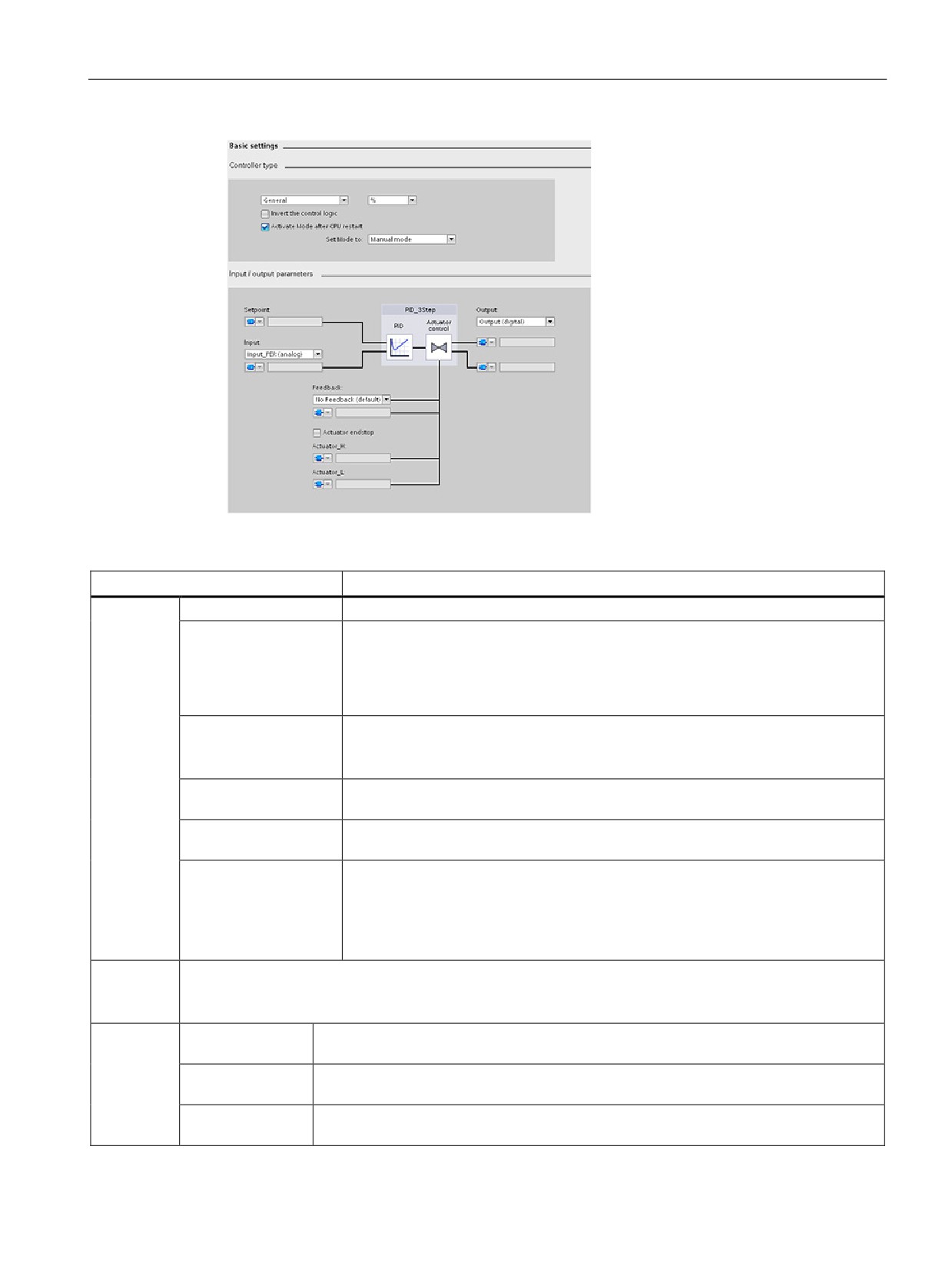
Example configuration settings for the PID_3Step instruction
Settings
Description
Basic
Controller type
Selects the engineering units.
Invert the control logic
Allows selection of a reverse-acting PID loop.
• If not selected, the PID loop is in direct-acting mode, and the output of PID loop
increases if the input value < setpoint).
• If selected, the output of the PID loop increases if the input value > setpoint.
Activate mode after
Restarts the PID loop after it is reset or if an input limit has been exceeded and
CPU restart
returned to the valid range.
Set Mode to: Defines the mode that the user wants the PID to go to after restart.
Input
Selects either the Input parameter or the Input_PER parameter (for analog) for the
process value. Input_PER can come directly from an analog input module.
Output
Selects either to use the digital outputs (Output_UP and Output_DN) or to use the
analog output (Output_PER) for the output value.
Feedback
Selects the type of device status returned to the PID loop:
• No feedback (default)
• Feedback
• Feedback_PER
Process
Scales both the range and the limits for the process value. If the process value goes below the low limit or
value
above the high limit, the PID loop goes to inactive mode and sets the output value to 0.
To use Input_PER, you must scale the analog process value (input value).
Actuator
Motor transition
Sets the time from open to close for the valve. (Locate this value on the data sheet or
time
the faceplate of the valve.)
Minimum ON time
Sets the minimum movement time for the valve. (Locate this value on the data sheet or
the faceplate of the valve.)
Minimum OFF
Sets the minimum pause time for the valve. (Locate this value on the data sheet or the
time
faceplate of the valve.)
223

PID is easy
8.8 Configuring the PID_Compact and PID_3Step controllers
Settings
Description
Reaction to error
Defines the behavior of the valve when an error is detected or when the PID loop is
reset. If you select to use a substitute position, enter the "Safety position". For analog
feedback or analog output, select a value between the upper or lower limit for the out-
put. For digital outputs, you can choose only 0% (off) or 100% (on).
Scale Position
• "High end stop" and "Lower end stop" define the maximum positive position (full-
Feedback1
open) and the maximum negative position (full-closed). "High end stop" must be
greater than "Lower end stop".
• "High limit process value" and "Low limit process value" define the upper and lower
positions of the valve during tuning and automatic mode.
• "FeedbackPER" ("Low" and "High") defines the analog feedback of the valve posi-
tion. "FeedbackPER High" must be greater than "FeedbackPER Low".
Advanced
Monitoring process
Sets the warning high and low limits for the process value.
value
PID parameters
If the user wishes, he can enter his own PID tuning parameters in this window. The
“Enable Manual Entry” check box must be checked to allow this.
1
"Scale Position Feedback" is editable only if you enabled "Feedback" in the "Basic" settings.
224
PID is easy
8.9 Configuring the PID_Temp controller
8.9
Configuring the PID_Temp controller
The parameters of the technology object determine the operation of the PID control-
ler. Use the icon to open the configuration editor.
Table 8- 14 Example configuration settings for the PID_Temp instruction
Settings
Description
Basic
Controller type
Selects the engineering units.
Activate mode
Restarts the PID loop after it is reset or if an input limit has been
after CPU restart
exceeded and returned to the valid range.
Set Mode to: Defines the mode that the user wants the PID to go to
after restart.
Input
Selects either the Input parameter or the Input_PER parameter (for
analog) for the process value. Input_PER can come directly from an
analog input module.
Output Heat
Selects either to use the digital outputs (OutputHeat and Out-
putHeat_PWM) or to use the analog output (OutputHeat_PER (ana-
log)) for the output value.
Output Cool
Selects either to use the digital outputs (OutputCool and Out-
putCool_PWM) or to use the analog output (OutputCool_PER (ana-
log)) for the output value.
Process
Scales both the range and the limits for the process value. If the process value goes be-
value
low the low limit or above the high limit, the PID loop goes to inactive mode and sets the
output value to 0.
To use Input_PER, you must scale the analog process value (input value).
Cascade
Controller is mas-
Sets the controller as a master and selects the number of slaves.
ter
Controller is slave
Sets the controller as a slave and selects the number of masters.
225

PID is easy
8.9 Configuring the PID_Temp controller
Controller type
Setting
TO-DB parameter
Data
Value range
Description
type
Physical
"PhysicalQuantity"
Int
• General
Pre-selection for physical
quantity
(Enu
unit value
• Temperature
m)
No multi-value control
(=default)
and not editable in online
mode of functional view.
Unit of
"PhysicalUnit
Int
• General: Units =
User unit selection is set
meas-
(Enu
back to “0” if you change
%
urement
m)
the physical quantity.
• Temperature:
Units (possible
selections) =
-
°C (=default)
–
°F
– K
Activate
"RunModeByStartup"
Bool
Checkbox
If set to TRUE (=default),
mode
the controller switches to
after
the state that is stored in
CPU
the “Mode” variable after
restart
a powercycle (Power on -
off - on) or PLC STOP-to-
RUN transition. Other-
wise, the PID_Temp
remains in “Inactive”
mode.
Set
"Mode"
Int
Modes (possible
The engineering station
mode to
(Enu
selections):
(ES) sets the start value
m)
of the“Mode” variable
•
0: Inactive
according to user selec-
•
1: Pretuning
tion.The default value of
•
2: Fine tuning
Mode (stored inTO-DB) is
Manual Mode.
•
3: Automatic
mode
•
4: Manual mode
(=default)
226

PID is easy
8.9 Configuring the PID_Temp controller
Input / output parameters
Setting
TO-DB parameter
Data
Value range
Description
type
Setpoint
Setpoint
Real)
Real
Only accessible in Prop-
erty Page.
No multi value control in
online mode of function-
al view.
Selection
"Config.InputPerOn"
Bool
Bool
Selects which kind of
input
(Enu
input to use.
m)
Possible selections:
• FALSE: “Input” (Re-
al)
• TRUE: “Input_PER
(analog)”
Input
Input or Input_PER
Real
Real or Int
Only accessible in Prop-
or Int
erties page.
No multi value control in
online mode of function-
al view.
Selection
"Config.Output.Heat.Select"
Int
2 >= Config.Output.
Selects which kind of
Output
(Enu
Heat.Select
output to use for heating.
(heating)
m)
>= 0
Possible selections:
•
“OutputHeat” (Real)
•
“OutputHeat_PWM”
(Bool) (=default)
•
“OutputHeat_PER
(analog)” (Word)
Is set to “OutputHeat”
once, if “This controller
is a master” checkbox in
the “Cascade” section is
activated by user.
Output
OutputHeat, OutputHeat_PER,
Real
Real, Int, or Bool
Only accessible in Prop-
(heating)
or OutputHeat_PWM
or Int
erties page.
or
No multi value control in
Bool
online mode of function-
al view.
227

PID is easy
8.9 Configuring the PID_Temp controller
Setting
TO-DB parameter
Data
Value range
Description
type
Activate
"Config.ActivateCooling"
Bool
Bool
Checking this checkbox:
output
•
Sets the "Con-
(cooling)
fig.Output.
Heat.PidLowerLimit
= 0.0 once.
•
Sets the
"Con-
fig.ActivateCooling"
parameter to TRUE,
instead of FALSE if
unchecked
(=default).
•
Activates all other
“Output (cooling)”
controls (in “Basic
settings” and other
views).
•
Changes the line
from the PID symbol
to the controls from
gray to black.
•
“This controller is a
master” checkbox in
the “Cascade” sec-
tion is disabled.
Note: Only available if
you do not configure the
controller as a master for
a cascade (“This control-
ler is a master”checkbox
in the “Cascade” section
is deactivated;
"Con-
fig.Cascade.IsMaster" =
FALSE).
228

PID is easy
8.9 Configuring the PID_Temp controller
Setting
TO-DB parameter
Data
Value range
Description
type
Selection
"Config.Output.Cool.Select"
Int
2 >= Config.Output.
Selects which kind of
Output
(Enu
Heat.Select
output to use for cooling.
(cooling)
m)
>= 0
Possible selections:
•
“OutputCool” (Real)
•
“OutputCool_PWM”
(Bool) (=default)
•
“OutputCool_PER
(analog)” (Word)
Only available if you
check “Activate output
(cooling)”;
(Config.ActivateCooling
= TRUE).
Output
OutputCool, OutputCool_PER,
Real
Real, Int, or Bool
Only accessible in Prop-
(cooling)
or OutputCool_PWM
or Int
erties page.
or
No multi value control in
Bool
online mode of function-
al view.
229

PID is easy
8.9 Configuring the PID_Temp controller
Cascade parameters
The following parameters enable you to select controllers as masters or slaves and to
determine the number of slave copntrollers that receive their setpoint directly from the
master controller:
Setting
TO-DB parameter
Data
Value range
Description
type
This
"Config.Cascade.IsMaster"
Bool
Bool
Shows if this controller is
controller
a master in a cascade.
is a
When you check this
master
checkbox, you perform
the following:
• Set the parameter
"Con-
fig.Cascade.IsMaster
" to TRUE, instead of
FALSE if unchecked
(=default).
• Set “Selection Output
(heating)” in “Input /
output parameters”
section to “Out-
putHeat” once (Con-
fig.Output.Heat.Selec
t = 0).
• Enable “Number of
Slaves” input field.
• Disable “Activate
output (cooling)”
checkbox in “Input /
output parameters”
section.
Note: Only available if
cooling output of this
controller is deactivated
(“Activate output (cool-
ing)” checkbox in “Input /
output parameters” sec-
tion deactivated (Con-
fig.ActivateCooling =
FALSE).
230

PID is easy
8.9 Configuring the PID_Temp controller
Setting
TO-DB parameter
Data
Value range
Description
type
Number
"Config.Cascade.CountSlaves"
Int
255 >= Con-
Number of slave control-
of slaves
fig.Cascade.
lers that get their set-
CountSlaves
point directly from this
>= 1
master controller. The
PID_Temp instruction
processes this value,
along with others, for
anti-windup-
handling."Number of
slaves is only available if
“This controller is a mas-
ter” checkbox is activat-
ed (Con-
(Con-
fig.Cascade.IsMaster =
TRUE).
This
"Config.Cascade.IsSlave"
Bool
Bool
Shows if this controller is
controller
a slave in a cascade.
is a
When you check this
slave
checkbox, you set the
parameter "Con-
fig.Cascade.IsSlave" to
TRUE, instead of FALSE
if unchecked (=default).
You must check this
checkbox in the property
page to enable the “Se-
lectionMaster” dropdown
list.
231
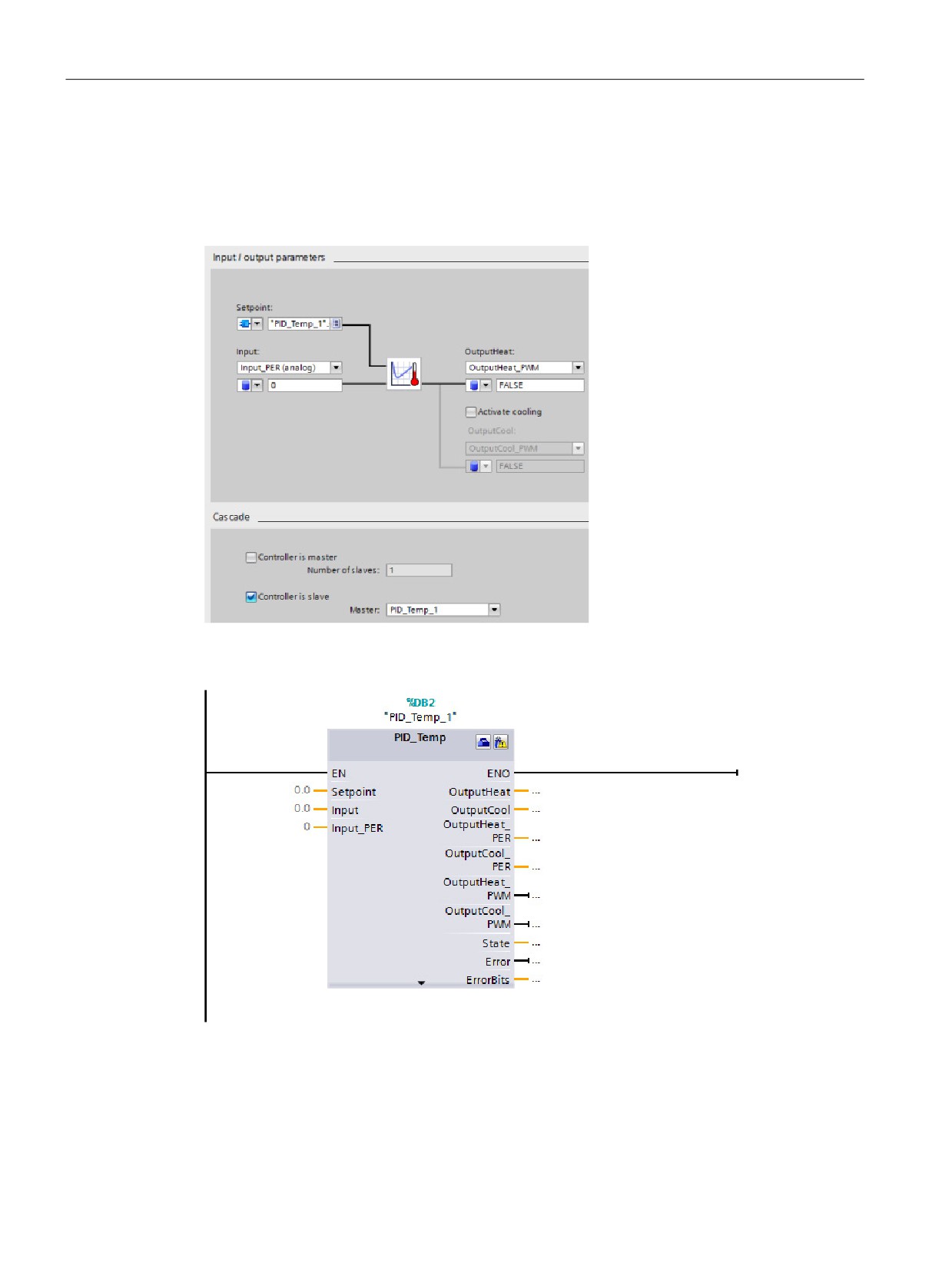
PID is easy
8.9 Configuring the PID_Temp controller
Example: Cascading controllers
In the “Basic settings” dialog below, you see the “Input / output parameters” section and the
“Cascade” section for slave controller "PID_Temp_2" after selecting "PID_Temp_1" as
master. You make the connections between master and slave controller:
Network 1: In these networks, you make the connection between the "PID_Temp_1" master
and the "PID_Temp_2" slave in the programming editor:
232
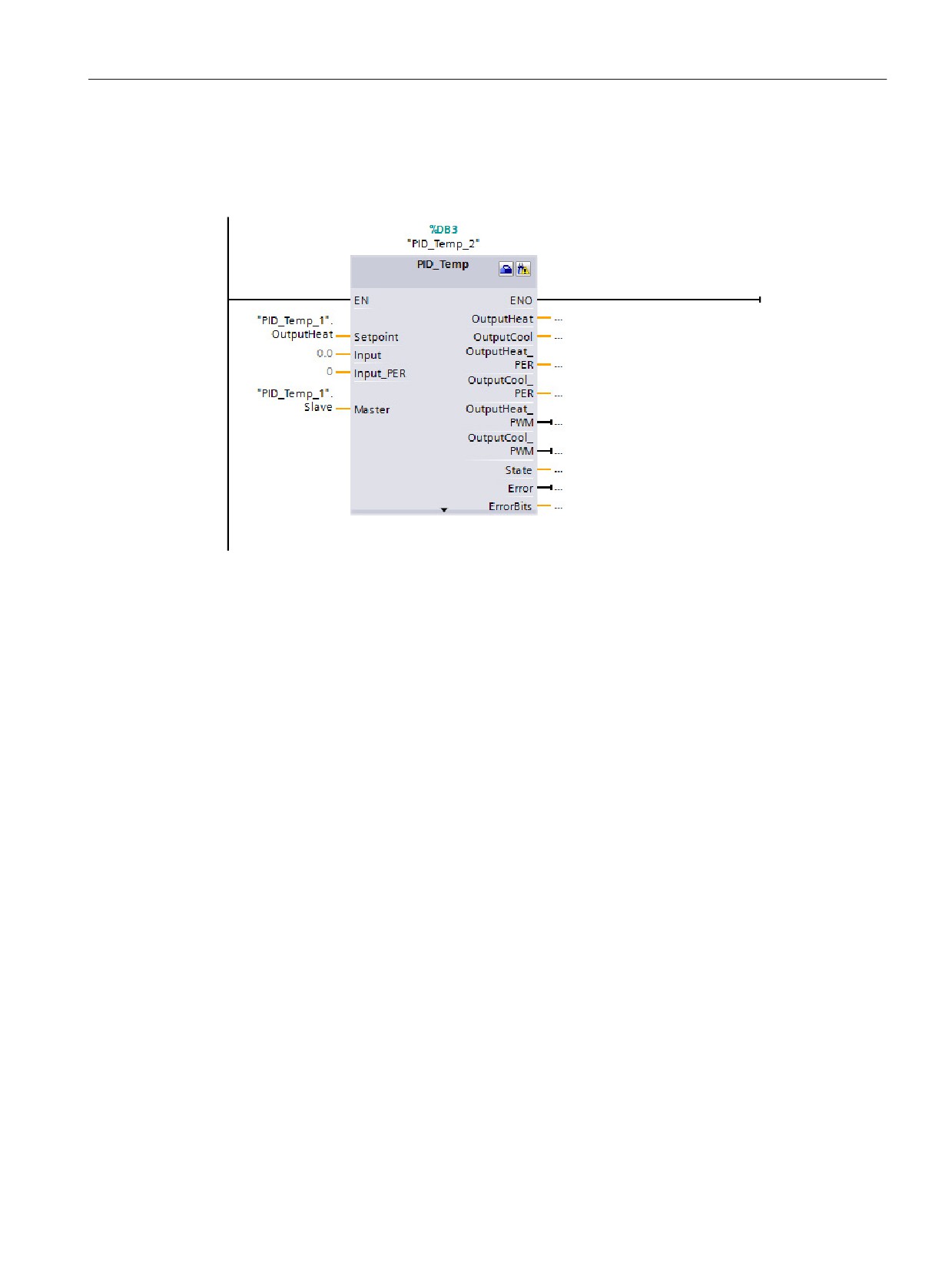
PID is easy
8.9 Configuring the PID_Temp controller
Network 2: You make the connection between the "PID_Temp_1" master’s “OutputHeat” and
"Slave" parameters to the "PID_Temp_2" slave’s “Setpoint” and "Master" parameters,
respectively:
Autotuning of temperature processes
The PID_Temp instruction provides two modes for auto tuning:
●
“Pretuning” (parameter “Mode” = 1)
●
“Finetuning” (parameter “Mode” = 2)
233

PID is easy
8.9 Configuring the PID_Temp controller
Depending on the controller configuration, different variants of these tuning methods are
available:
Configuration
Controller with heating
Controller with heating and
Controller with heating and
output
cooling output using cool-
cooling output using two
ing factor
sets of PID parameters
Associated
• Config.ActivateCooling
• Config.ActivateCooling
• Config.ActivateCooling
TO-DB values
= FALSE
= TRUE
= TRUE
• Con-
• Con-
• Con-
fig.AdvancedCooling
fig.AdvancedCooling =
fig.AdvancedCooling =
= irrelevant
FALSE
TRUE
Available tun-
•
“Pretuning heating”
•
“Pretuning heating”
•
“Pretuning heating and
ing methods
cooling”
•
“Fine tuning heating"
•
“Fine tuning heating"
(cooling offset cannot
(cooling offset can be
• "Pretuning heating”
be used)
used)
•
“Pretuning cooling”
•
“Fine tuning heating”
(cooling offset can be
used)
•
“Fine tuning cooling”
(heating offset can be
used)
234
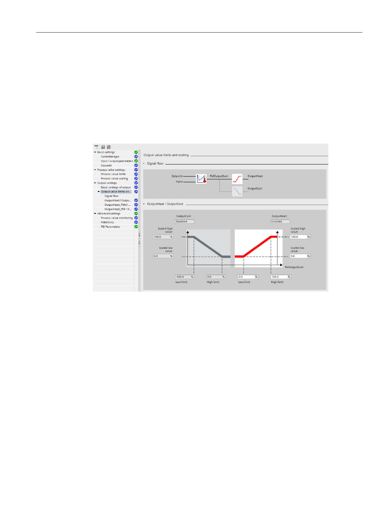
PID is easy
8.9 Configuring the PID_Temp controller
Output value limits and scaling
Cooling activation disabled
If you configure the PID_Temp instruction as master for a cascade “Activate output (cooling)”
checkbox in “Basic settings” view is unchecked and disabled, all settings in the “Output
settings” view that depend on cooling activation are disabled, too.
The figure below shows the "Output value limits and scaling” section in the “Output settings”
view with cooling deactivated (OutputHeat_PWM selected in “Input / output parameters” view
and OutputHeat always enabled):
235
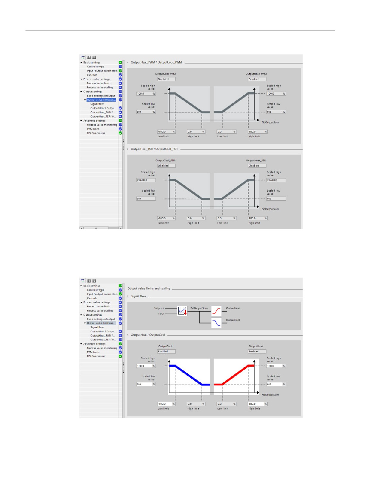
PID is easy
8.9 Configuring the PID_Temp controller
Cooling activation enabled
The figure below shows the ”Output value limits and scaling” section in “Output settings”
view with cooling activated (OutputCool_PER and OutputHeat_PWM selected in “Input /
output parameters” view; OutputCool and OutputHeat always enabled):
236
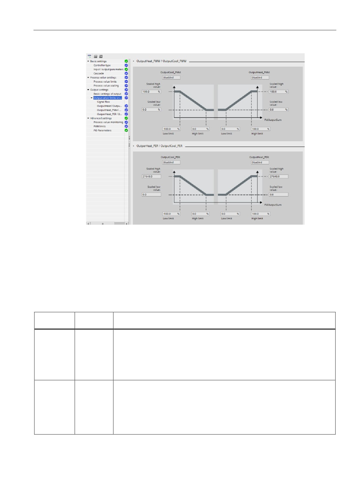
PID is easy
8.9 Configuring the PID_Temp controller
Operation modes
To change the mode of operation manually, the user needs to set the “Mode” in-out
parameter of the controller and activate it by setting “ModeActivate” from FALSE to TRUE
(rising edge triggered). You must reset “ModeActivate” before the next mode change; it does
not reset automatically.
Output parameter “State” shows the current operating mode and is set to the requested
“Mode” if possible. The “State” parameter cannot be changed directly; it is only changed
through the “Mode” parameter or automatic operating mode changes by the controller.
"Mode" /
Name
Description
"State"
0
Inactive
The PID_Temp instruction:
• Deactivates the PID-algorithm and pulse width modulation
• Sets to "0" (FALSE) all controller outputs (OutputHeat, OutputCool, Out-
putHeat_PWM,OutputCool_PWM, OutputHeat_PER, OutputCool_PER), regardless of
configured output limits or offsets. You can reach this mode by setting “Mode” = 0,
“Reset” = TRUE, or by error.
1
Pretuning
This mode determines the parameters during first start up of the controller.
(startup tun-
Unlike the PID_Compact, for the PID_Temp, you must select if you require heating tuning,
ing / SUT)
cooling tuning, or both with the “Heat.EnableTuning” and “Cool.EnableTuning” parame-
ters.
You can activate "Pretuning" from Inactive, Automatic mode, or Manual mode.
If tuning is successful, PID_Temp switches to Automatic mode. If tuning is unsuccessful,
the switchover of the operating mode depends on “ActivateRecoverMode”.
237

PID is easy
8.9 Configuring the PID_Temp controller
"Mode" /
Name
Description
"State"
2
Fine tuning
This mode determines the optimum parameterization of the PID controller at the setpoint.
(tuning in run
Unlike the PID_Compact, for the PID_Temp, you must select if you require heating tuning
/ TIR)
or cooling tuning with the “Heat.EnableTuning” and “Cool.EnableTuning” parameters.
You can activate "Finetuning" from Inactive, Automatic mode, or Manual mode.
If tuning is successful, PID_Temp switches to Automatic mode. If tuning is not successful,
the switchover of the operating mode depends on “ActivateRecoverMode”.
3
Automatic
In Automatic mode (the standard PID control mode), the result of the PID-algorithm de-
mode
termines the output values.
PID_Temp switches to Inactive if an error occurs and “ActivateRecoverMode” = FALSE. If
an error occurs and “ActivateRecoverMode” = TRUE, the switchover of the operating
mode depends on the error. Refer to PID_Temp instruction ErrorBit parameters
(Page 220) for further information.
4
Manual mode
In this mode, the PID controller scales, limits, and transfers the value of parameter “Man-
ualValue” to the outputs.
The PID controller assigns “ManualValue” in the scaling of the PID-algorithm
(like“PidOutputSum”), so its value decides if it is effective at the heating or cooling out-
puts.
You can reach this mode by setting “Mode” = 4 or “ManualEnable”= TRUE.
5
Substitute
You can activate this mode by setting "Mode" = 5. The mode is an automatic error reac-
output value
tion of the controller if Automatic mode is active at the moment the error occurs:
with error
• SetSubstituteOutput = FALSE (Last valid output value)
monitoring
(Recover
• SetSubstituteOutput = TRUE (Value stored in parameter "SubstituteOutput")
mode)
When PID_Temp is in “Automatic mode” and the “ActivateRecoverMode” parameter =
TRUE, PID_Temp changes to this
mode in the case of the following errors:
•
“Invalid value at "Input_PER" parameter. Check for an error at the analog input (for
example, wire broken)." (ErrorBits = DW#16#0002)
•
“Invalid value at "Input" parameter. Value is not a number.” (ErrorBits = DW#16#0200)
•
“Calculation of output value failed. Check the PID parameters.” (ErrorBits =
DW#16#0400)
•
“Invalid value at "Setpoint" parameter. Value is not a number.” (ErrorBits =
DW#16#1000)
If the error is no longer pending, PID_Temp will switch back to Automatic mode automati-
cally.
238
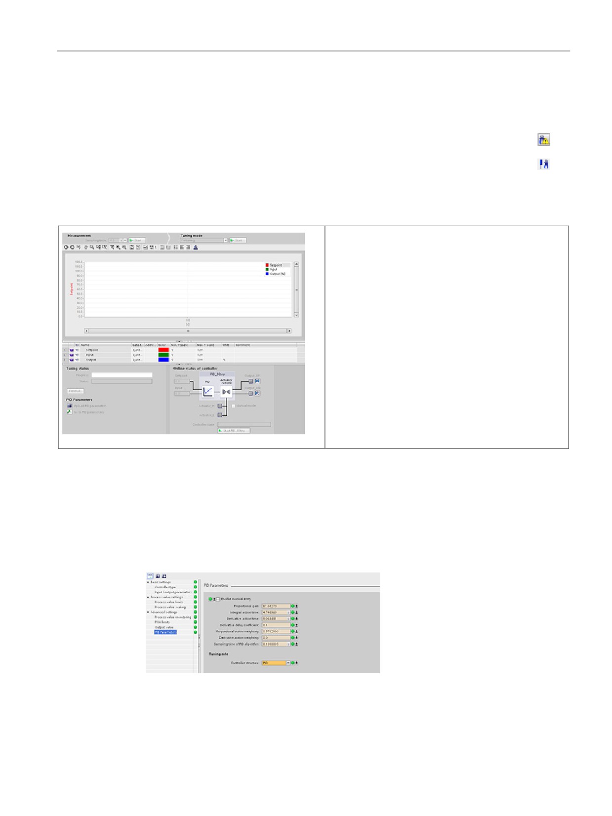
PID is easy
8.10 Commissioning the PID_Compact and PID_3Step controllers
8.10
Commissioning the PID_Compact and PID_3Step controllers
Use the commissioning editor to configure the PID controller for autotuning at startup
and for autotuning during operation. To open the commissioning editor, click the icon
on either the instruction or the project navigator.
Table 8- 15 Sample commissioning screen (PID_3Step)
• Measurement: To display the setpoint, the pro-
cess value (input value) and the output value in a re-
al-time trend, enter the sample time and click the
"Start" button.
• Tuning mode: To tune the PID loop, select either
"Pre-tuning" or "Fine tuning" (manual) and click the
"Start" button. The PID controller runs through multi-
ple phases to calculate system response and update
times. The appropriate tuning parameters are calcu-
lated from these values.
After the completion of the tuning process, you can
store the new parameters by clicking the "Upload PID
parameters" button in the "PID Parameters" section of
the commissioning editor.
If an error occurs during tuning, the output value of the
PID goes to 0. The PID mode then is set to "inactive"
mode. The status indicates the error.
PID start value control
You can edit the actual values of the PID configuration parameters so that the behavior of
the PID controller can be optimized in online mode.
Open the "Technology objects" for your PID controller and its "Configuration" object. To
access the start value control, click the "eyeglasses icon" in the upper left corner of the
dialog:
239
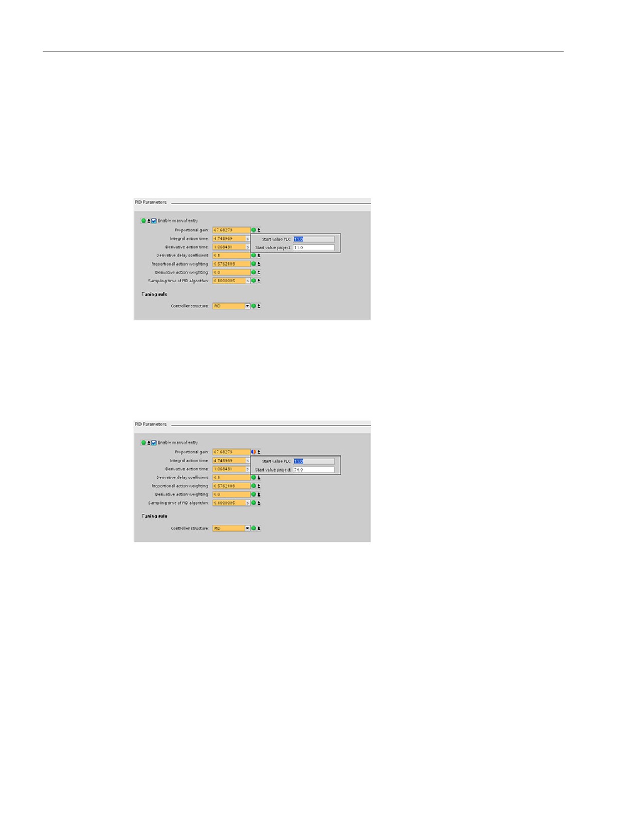
PID is easy
8.10 Commissioning the PID_Compact and PID_3Step controllers
You can now change the value of any of your PID controller configuration parameters as
shown in the figure below.
You can compare the actual value to the project (offline) start value and the PLC (online)
start value of each parameter. This is necessary to compare online/offline differences of the
Technology object data block (TO-DB) and to be informed about the values that will be used
as current values on the next Stop-to-Start transition of the PLC. In addition, a compare icon
gives a visual indication to help easily identify online/offline differences:
The figure above shows the PID parameter screen with compare icons showing which
values are different between online and offline projects. A green icon indicates that the
values are the same; a blue/orange icon indicates that the values are different.
Additionally, click the parameter button with the downward arrow to open a small window
that shows the project (offline) start value and the PLC (online) start value of each
parameter:
240
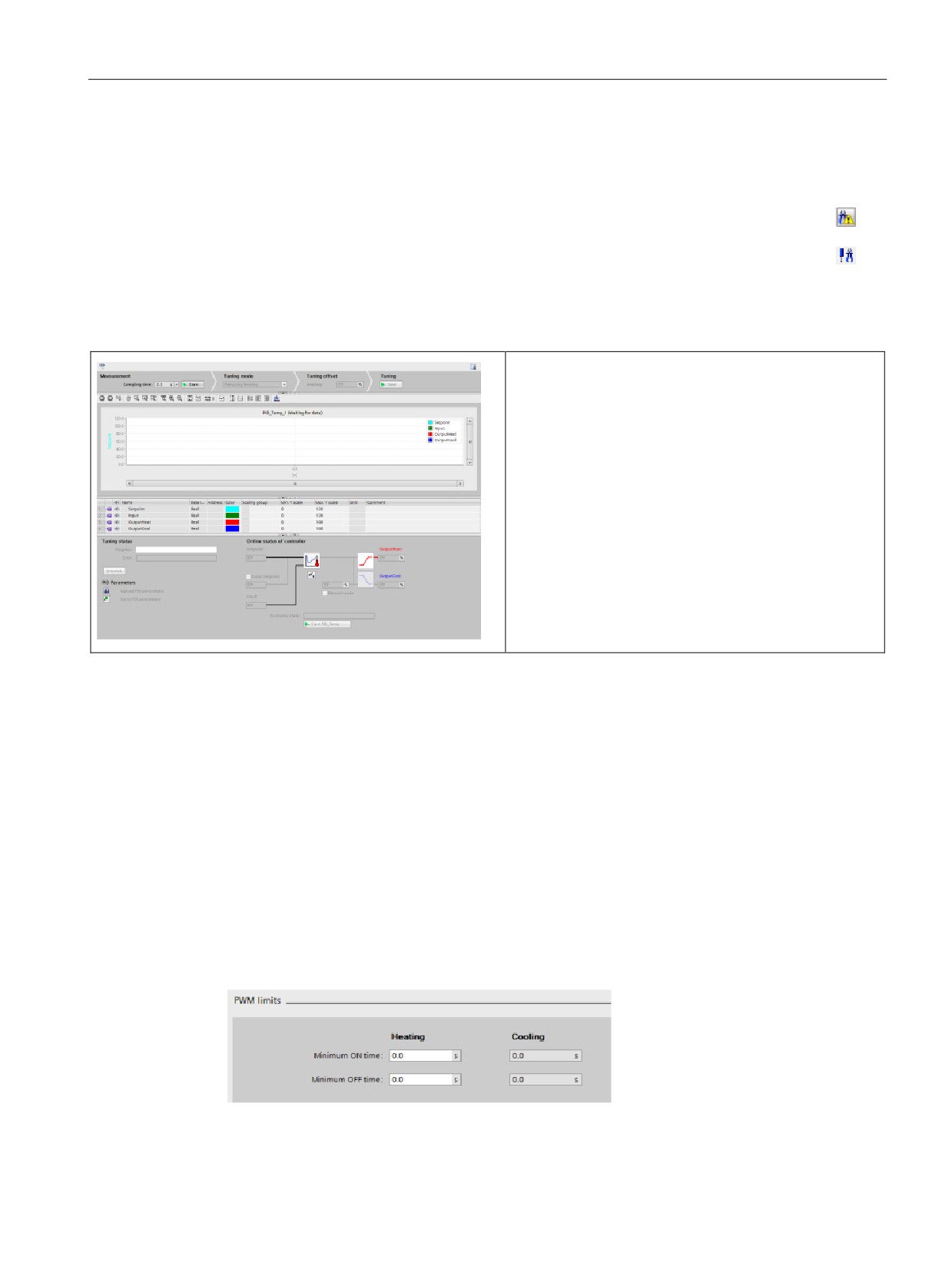
PID is easy
8.11 Commissioning the PID_Temp controller
8.11
Commissioning the PID_Temp controller
Use the commissioning editor to configure the PID controller for autotuning at startup
and for autotuning during operation. To open the commissioning editor, click the icon
on either the instruction or the project navigator.
Table 8- 16 Sample commissioning screen (PID_Temp)
Measurement: To display the setpoint, the process value
(input value) and the output value in a real-time trend,
enter the sample time and click the "Start" button.
Tuning mode: To tune the PID_Temp loop, select either
"Pretuning" or "Finetuning" (manual) and click the "Start"
button. The PID controller runs through multiple phases
to calculate system response and update times. The
appropriate tuning parameters are calculated from these
values.
After the completion of the tuning process, you can store
the new parameters by clicking the "Upload PID parame-
ters" button in the "PID Parameters" section of the com-
missioning editor.
If an error occurs during tuning, the output value of the
PID goes to "0". The PID mode then is set to "inactive"
mode. The status indicates the error.
PWM limits
Actuators that are controlled with the software PWM function of the PID_Temp may need to
be protected from too short pulse durations (for example, a thyristor relay needs to be turned
on for more than 20 ms before it can react at all); you assign a minimum on time. The
actuator can also neglect short impulses and therefore corrupt the control quality. A
minimum off time can be necessary (for example, to prevent overheating).
To show up the PWM limits view, you must open the functional view in the Technology
objects (TO) configuration and select “PWM limits” from the “Advanced settings” node in the
navigation tree.
If you open the “PWM limits” view in the functional view and activate monitoring
(“glasses”button), all controls show the online monitor value from TO-DB with orange
background color and multi-value control, and you can edit the values (if configuration
conditions are fulfilled; refer to the table below).
241

PID is easy
8.11 Commissioning the PID_Temp controller
Setting
TO-DB parameter
Data
Value range
Description
type
Minimum
"Config.Output.Heat.
Real
100000.0
A pulse at Out-
on
MinimumOnTime"
>= "Config.Output.
putHeat_PWM" is
Heat.
never shorter than this
time (heat-
MinimumOnTime
value.
ing) 1,2
>= 0.0
Minimum
"Config.Output.Heat.
Real
100000.0
A break at Out-
off
MinimumOffTime"
>= "Config.Output.
putHeat_PWM is nev-
Heat.
er shorter than this
time (heat-
MinimumOffTime
value.
ing)
1,2
>= 0.0
Minimum
"Config.Output.Cool.
Real
100000.0
A pulse at Out-
on
MinimumOnTime"
>= Config.Output.
putCool_PWM is nev-
Cool.
er shorter than this
time (cool-
1,3,4
MinimumOnTime
value.
ing)
>= 0.0
Minimum
"Config.Output.Cool.
Real
100000.0
A break at Out-
off
MinimumOffTime"
>= Config.Output.
putCool_PWM is nev-
Cool.
er shorter than this
time (cool-
MinimumOffTime
value.
ing) 1,3,4
>= 0.0
1
The field displays "s" (seconds) as the time units.
2
If the·selection Output (heating) in “Basic settings” view is not “OutputHeat_PWM” (Con-
fig.Output.Heat.Select = TRUE), you should set this value to "0.0".
3
If selection Output (cooling) in “Basic settings” view is not “OutputCool_PWM” (Con-
fig.Output.Cool.Select = TRUE), you should set this value to "0.0".
4
Only available if you check “Activate output (cooling)” in “Basic settings” view (Con-
fig.ActivateCooling = TRUE).
242