Siemens simatic S7-1200. Manual (2015) - page 5
PID is easy
8.11 Commissioning the PID_Temp controller
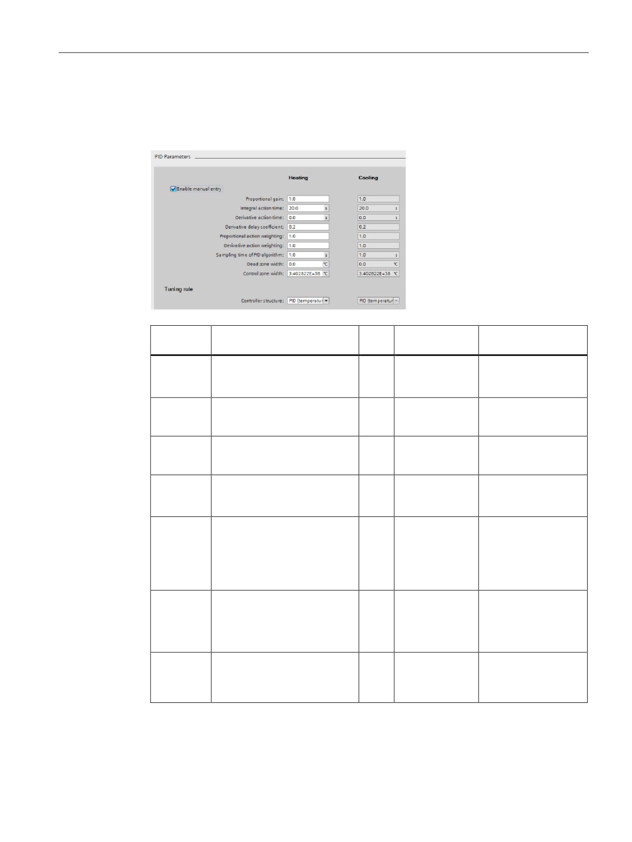
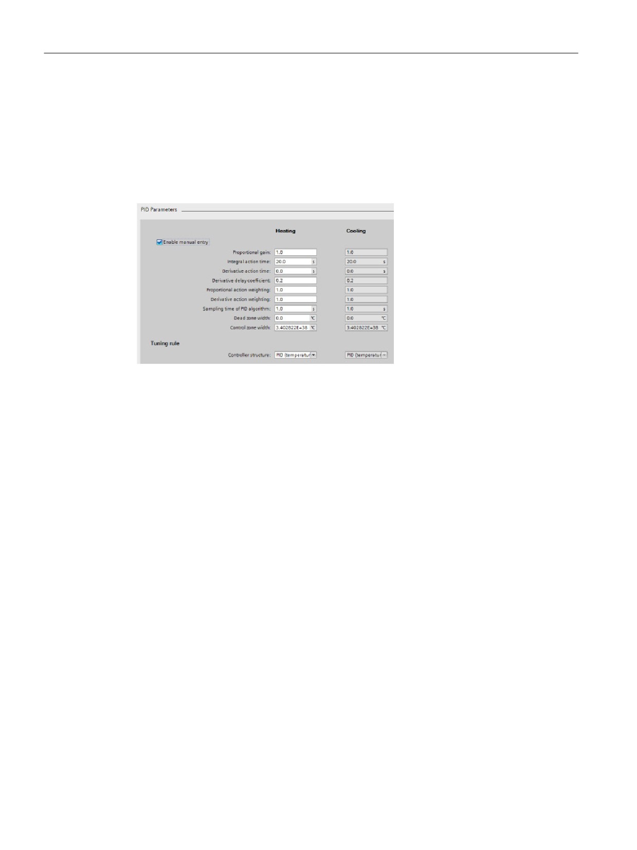
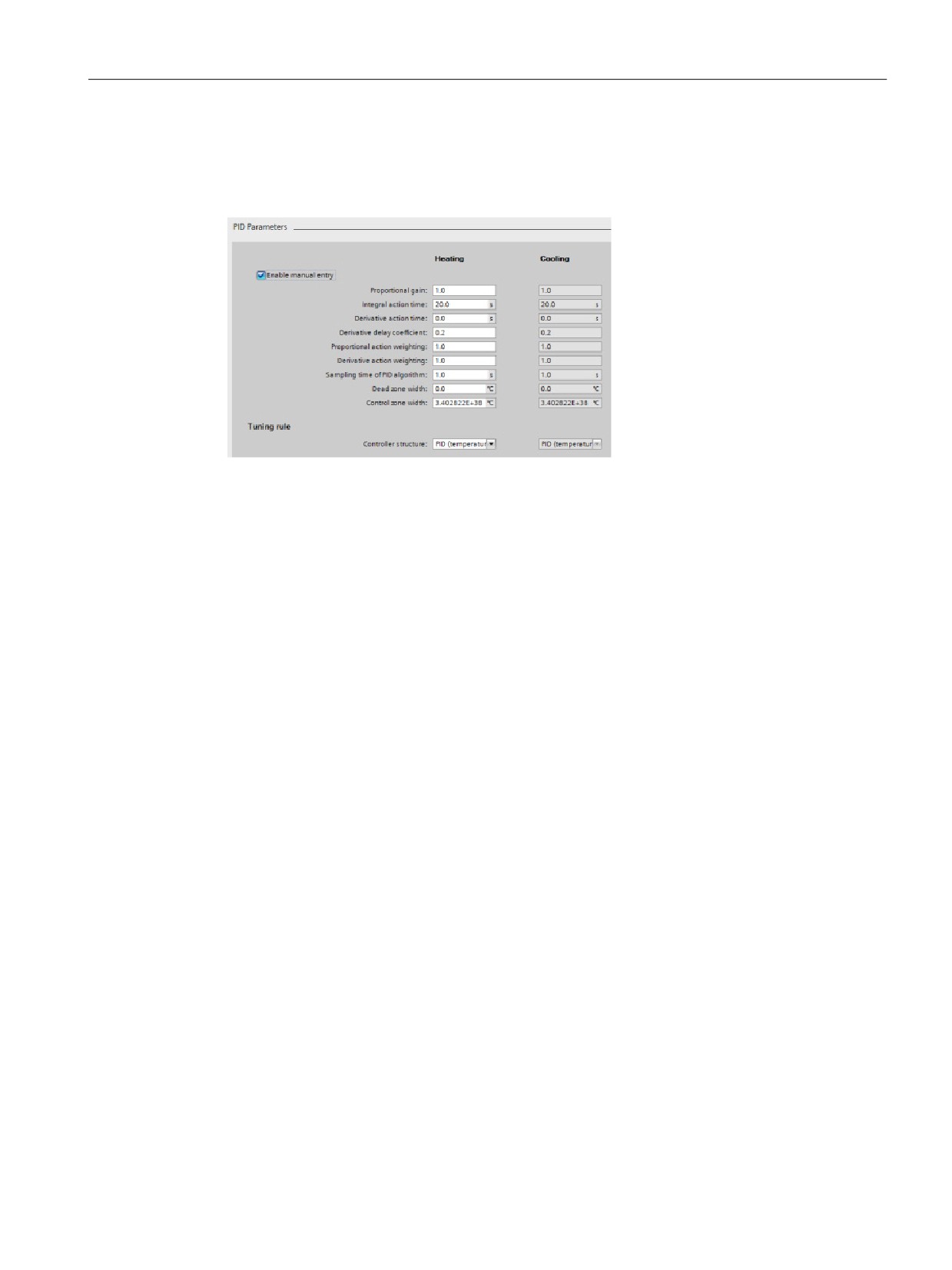
PID parameters
The “Advanced settings” view, "PID Parameters” section is shown below with the cooling
and/or “PID parameterswitchover” feature deactivated.
Setting
TO-DB parameter
Data
Value range
Description
type
Enable
"Retain.CtrlParams.
Bool
Bool
You must check this
SetByUser"
checkbox to enter PID
manual
parameters manually.
entry
Proportional
"Retain.CtrlParams.
Real
Gain >= 0.0
PID proportional gain
gain (heat-
Heat.Gain"
for heating
ing) 2
Integral
"Retain.CtrlParams.
Real
100000.0 >=
PID integral action for
action time
Heat.Ti"
Ti >= 0.0
heating.
(heating) 1,2
Derivative
"Retain.CtrlParams.
Real
100000.0 >=
PID derivative action
action time
Heat.Td"
Td >= 0.0
time for heating.
(heating) 1,2
Derivative
"Retain.CtrlParams.
Real
TdFiltRatio >=
PID derivative delay
delay coeffi-
Heat.TdFiltRatio"
0.0
coefficient for heating
cient(heatin
that defines the deriva-
g) 2
tive lag time as coeffi-
cient from the PID
derivative time.
Proportional
"Retain.CtrlParams.
Real
1.0 >=PWeighting
Weighting of the PID
action
Heat.PWeighting"
>= 0.0
proportional gain for
weighting(h
heating in either direct-
eating) 2
or loopback- control
path.
Derivative
"Retain.CtrlParams.
Real
1.0 >=DWeighting
Weighting of the PID
action
Heat.DWeighting"
>= 0.0
derivative part for heat-
weighting
ing in either direct- or
(heating) 2
loopback- control path.
243

PID is easy
8.11 Commissioning the PID_Temp controller
Setting
TO-DB parameter
Data
Value range
Description
type
Sampling
"Retain.CtrlParams.
Real
100000.0
Internal call cycle of the
time of PID
Heat.Cycle"
>=Cycle
PID controller for heat-
algorithm
> 0.0
ing.
(heating) 1,2
Rounded to an integer
multiple of the FB call
cycle time.
Deadband
"Retain.CtrlParams.
Real
DeadZone>= 0.0
Width of the deadband
width(heatin
Heat.DeadZone"
for heating control
g) 2,3
deviation.
Control
"Retain.CtrlParams.
Real
ControlZone> 0.0
Width of the control
Zone (heat-
Heat.ControlZone"
deviation zone for heat-
ing)2,3
ing where PID control is
active. If control devia-
tion leaves this range,
output is switched to
maximum output val-
ues.
Default value is
"MaxReal" so control
zone is deactivated as
long as autotuning is
not executed.
Value "0.0" is prohibit-
ed for Control Zone;
with the value "0.0",
PID_Temp behaves like
a two-position controller
that is always heating
or cooling at full power.
244
PID is easy
8.11 Commissioning the PID_Temp controller
Setting
TO-DB parameter
Data
Value range
Description
type
Controller
"PIDSelfTune.SUT.
Int
"PIDSelf-
You can select the
structure
TuneRuleHeat",
Tune.SUT.
tuning algorithm for
(heating)
TuneRuleHeat"
heating.
"PIDSelfTune.TIR.
= 0..2,
TuneRuleHeat"
Possible selections:
"PIDSelf-
• PID (Temperature)
Tune.TIR.
(=default)
TuneRuleHeat"
= 0..5
("PIDSelfTune.SUT.
TuneRuleHeat" = 2)
("PIDSelfTune.TIR.
TuneRuleHeat" = 0)
• PID
("PIDSelfTune.SUT.
TuneRuleHeat" = 0)
("PIDSelfTune.TIR.
TuneRuleHeat" = 0)
• PI
("PIDSelfTune.SUT.
TuneRuleHeat" = 1)
("PIDSelfTune.TIR.
TuneRuleHeat" = 4)
Any other combination
shows “User defined”,
but “User defined” is
not provided by default.
“PID (Temperature)” is
new for PID_Temp,
with a specific pretun-
ing (SUT) method for
temperature processes.
Proportional
"Retain.CtrlParams.
Real
Gain >= 0.0
PID proportional gain
gain (cool-
Cool.Gain"
for cooling
ing) 4
Integral
"Retain.CtrlParams.
Real
100000.0 >=Ti
PID integral action for
action time
Cool.Ti"
>= 0.0
cooling
(cooling) 1,4
Derivative
"Retain.CtrlParams.
Real
100000.0 >=Td
PID derivative action
action time
Cool.Td"
>= 0.0
time for cooling
(cooling) 1,4
Derivative
Retain.CtrlParams.
Real
TdFiltRatio>= 0.0
PID derivative delay
delay coeffi-
Cool.TdFiltRatio"
coefficient for cooling
cient (cool-
that defines the deriva-
ing) 4
tive lag time as a coef-
ficient from the PID
derivative time.
245
PID is easy
8.11 Commissioning the PID_Temp controller
Setting
TO-DB parameter
Data
Value range
Description
type
Proportional
"Retain.CtrlParams.
Real
1.0 >=PWeighting
Weighting of the PID
action
Cool.PWeighting"
>= 0.0
proportional gain for
weighting
cooling in either the
(cooling) 4
direct- or loopback-
control path.
Derivative
Retain.CtrlParams.
Real
1.0 >=DWeighting
Weighting of the PID
action
Cool.DWeighting"
>= 0.0
derivative part for cool-
weighting
ing in either the direct-
(cooling) 4
or loopback- control
path.
Sampling
"Retain.CtrlParams.
Real
100000.0
Internal call cycle of the
time of PID
Cool.Cycle"
>=Cycle
PID controller for cool-
algorithm
> 0.0
ing.
(cooling) 1,4
Rounded to an integer
multiple of the FB call
cycle time.
Deadband
"Retain.CtrlParams.
Real
DeadZone>= 0.0
Width of the deadband
width (cool-
Cool.DeadZone"
for cooling control devi-
ing) 3,4
ation
246

PID is easy
8.11 Commissioning the PID_Temp controller
Setting
TO-DB parameter
Data
Value range
Description
type
Control
"Retain.CtrlParams.
Real
ControlZone> 0.0
Width of the control
Zone (cool-
Cool.ControlZone"
deviation zone for cool-
ing) 3,4
ing where PID control is
active. If control devia-
tion leaves this range,
output is switched to
maximum output val-
ues.
Default value is
"MaxReal" so control
zone is deactivated as
long as autotuning is
not executed.
Value "0.0" is prohibit-
ed for Control Zone;
with the value "0.0",
PID_Temp behaves like
a two-position controller
that is always heating
or cooling at full power.
247

PID is easy
8.11 Commissioning the PID_Temp controller
Setting
TO-DB parameter
Data
Value range
Description
type
Controller
"PIDSelfTune.SUT.
Int
"PIDSelf-
You can select the
structure
TuneRuleCool",
Tune.SUT.
tuning algorithm for
(cooling)
TuneRuleHeat"
cooling.
"PIDSelfTune.TIR.
= 0..2,
TuneRuleCool"
Possible selections:
"PIDSelf-
• PID (Temperature)
Tune.TIR.
(=default)
TuneRuleHeat"
= 0..5
("PIDSelfTune.SUT.
TuneRuleCool" = 2)
("PIDSelfTune.TIR.
TuneRuleCool = 0)
• PID
("PIDSelfTune.SUT.
TuneRuleCool" = 0)
("PIDSelfTune.TIR.
TuneRuleCool" = 0)
• PI
("PIDSelfTune.SUT.
TuneRuleCool" = 1)
("PIDSelfTune.TIR.
TuneRuleCool" = 4)
Any other combination
shows “User defined”,
but “User defined” is
not provided by default.
“PID (Temperature)” is
new for PID_Temp,
with a specific pretun-
ing (SUT) method for
temperature processes.
Only available if you
check/select the follow-
ing items: “Activate
output (cooling)” in
“Basic settings” view
("Con-
fig.ActivateCooling" =
TRUE), and “PID pa-
rameter switchover” in
“Output settings” view
(Con-
fig.AdvancedCooling =
TRUE).
248
PID is easy
8.11 Commissioning the PID_Temp controller
Setting
TO-DB parameter
Data
Value range
Description
type
1
The field displays "s" (seconds) as the time units.
2
Only available if you check "Enable manual entry” in PID parameters ("Re-
tain.CtrlParams.SetByUser" = TRUE).
3
Unit of measurement is displayed at the end of the field as selected in “Basic settings” view.
4
Only available if you check/select the following items: "Enable manual entry” in PID parameters
("Retain.CtrlParams.SetByUser" = TRUE), “Activate output (cooling)” in “Basic settings” view
("Config.ActivateCooling" = TRUE), and “PID parameter switchover” in “Output settings” view
(Config.AdvancedCooling = TRUE).
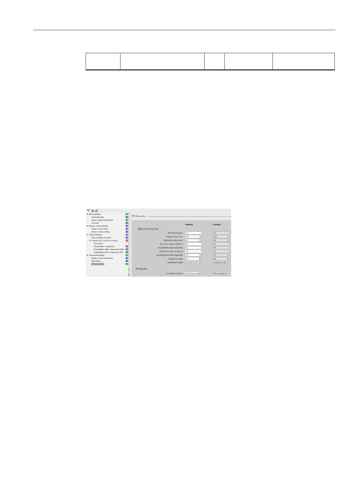
PID start value control
You can edit the actual values of the PID configuration parameters so that the behavior of
the PID controller can be optimized in online mode.
Open the "Technology objects" for your PID controller and its "Configuration" object. To
access the start value control, click the "eyeglasses icon" in the upper left corner of the
dialog:
249
PID is easy
8.11 Commissioning the PID_Temp controller
You can now change the value of any of your PID controller configuration parameters as
shown in the figure below.
You can compare the actual value to the project (offline) start value and the PLC (online)
start value of each parameter. This is necessary to compare online/offline differences of the
Technology object data block (TO-DB) and to be informed about the values that will be used
as current values on the next Stop-to-Start transition of the PLC. In addition, a compare icon
gives a visual indication to help easily identify online/offline differences:
The figure above shows the PID parameter screen with compare icons showing which
values are different between online and offline projects. A green icon indicates that the
values are the same; a blue/orange icon indicates that the values are different.
250
PID is easy
8.11 Commissioning the PID_Temp controller
Additionally, click the parameter button with the downward arrow to open a small window
that shows the project (offline) start value and the PLC (online) start value of each
parameter:
251
PID is easy
8.11 Commissioning the PID_Temp controller
252
Web server for easy Internet connectivity
9
The Web server provides Web page access to data about your CPU and to the process data
within the CPU. With these Web pages, you access the CPU (or Web-enabled CP) with the
Web browser of your PC or mobile device. The standard web pages allow authorized users
to perform these functions and more:
● Changing the operating mode (STOP and RUN) of the CPU
● Monitoring and modifying PLC tags, data block tags, and I/O values
● Viewing and downloading data logs
● Viewing the diagnostic buffer of the CPU.
● Updating the firmware of the CPU.
The Web server also allows you to create user-defined Web pages that can access CPU
data. You can develop these pages with the HTML authoring software of your choice. You
insert pre-defined "AWP" (Automation Web Programming) commands in your HTML code to
access the data in the CPU.
You set up users and privilege levels for the Web server in the device configuration for the
CPU in STEP 7.
Web browser requirement
The Web server supports the following PC Web browsers:
● Internet Explorer 8.0
● Internet Explorer 9.0
● Mozilla Firefox 17.0.1
● Google Chrome 23.0
● Apple Safari 5.1.7 (Windows)
● Apple Safari 6.0.2 (Mac)
The Web server supports the following mobile device Web browsers:
● Internet Explorer 6.0 and earlier, for HMI panels
● Mobile Safari 7534.48.3 (iOS 5.0.1)
● Mobile Android Browser 2.3.4
● Mobile Google Chrome 23.0
For browser-related restrictions that can interfere with the display of standard or user-defined
Web pages, see the topics about constraints (Page 256).
253
Web server for easy Internet connectivity
9.1 Easy to use the standard Web pages
9.1
Easy to use the standard Web pages
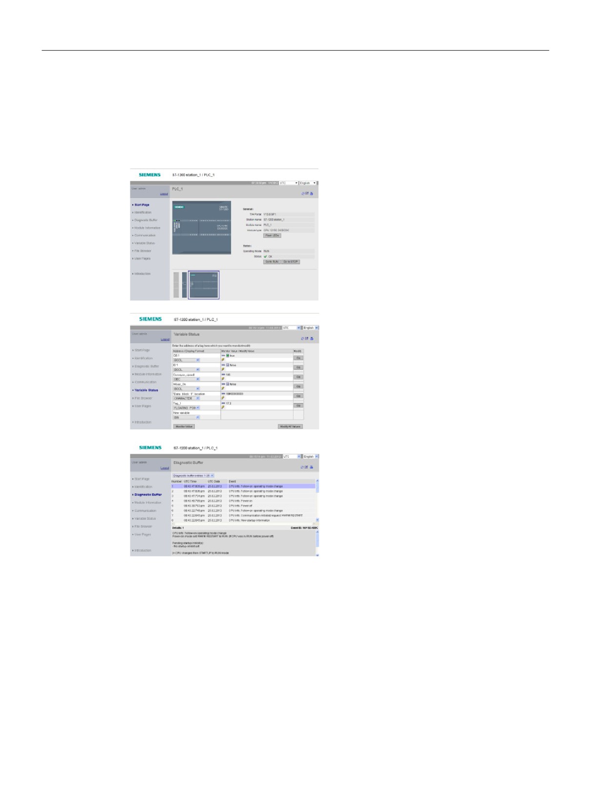
Using the standard Web pages is easy! You only have to enable the Web server when
configuring the CPU and configure Web server users with privileges to perform the tasks
they need to do.
The Start page displays a representation of
the CPU to which you are connected and lists
general information about the CPU. If you
have Web-server enabled CPs the Start page
also displays them and allows you to connect
to Web pages through those CPs.
If you have the required privileges, you can
change the operating mode of the CPU
(STOP and RUN) or flash the LEDs.
The Variable Status page allows you to moni-
tor or modify any of the I/O or memory data in
your CPU. You must have the "read variable
status" privilege to monitor values, and the
"write variable status" privilege to modify val-
ues. You can enter a direct address (such as
I0.0), a PLC tag name, or a tag from a specific
program block. The data values automatically
refresh until you disable the automatic refresh
option.
The Diagnostic Buffer page displays the diag-
nostic buffer, and is accessible to users with
privileges to query diagnostics. You can select
the range of diagnostic entries to be dis-
played.
The diagnostic entries list the events that oc-
curred and the CPU time and date of when
the event occurred. Select the individual event
to display detailed information about that
event.
254
Web server for easy Internet connectivity
9.1 Easy to use the standard Web pages
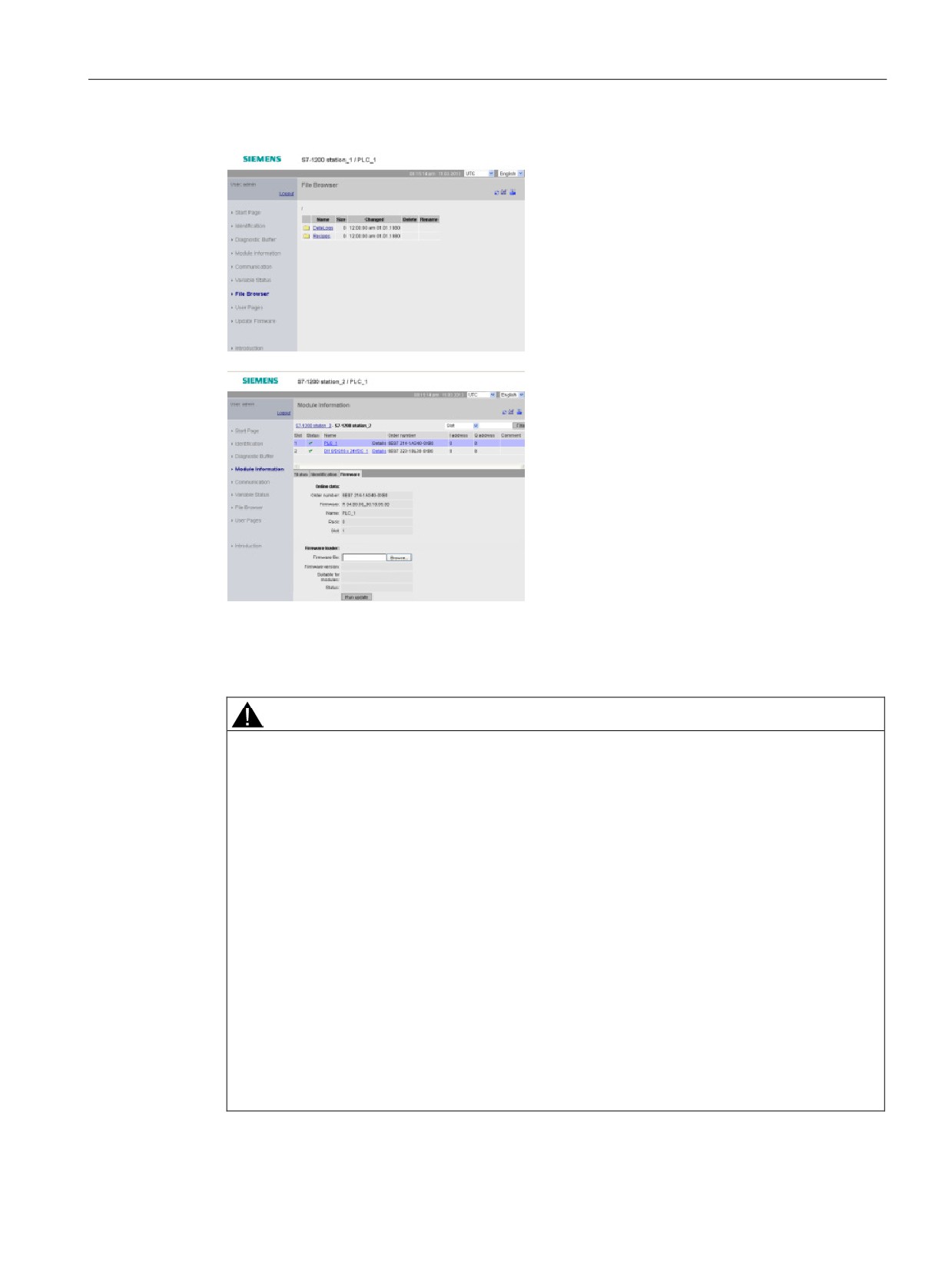
The File Browser page allows you to view,
download, or edit files in the load memory of
the CPU such as data logs (Page 122) and
recipes. Unless the CPU has Level 4 protec-
tion, all users can view the files from the File
Browser page. Users with privileges to modify
files can delete, edit and rename files.
The Module Information page in addition to
displaying information about the modules in
your station allows you to update the version
of firmware in your CPU or other modules that
support firmware update. Users with privileges
to query diagnostics can view the module
information page. Users with privileges to
perform a firmware update can update firm-
ware.
Other standard web pages display information about the CPU (such as the serial number,
the version and the article number) and about the communication parameters (such as
network addresses and physical properties of the communication interfaces).
WARNING
Unauthorized access to the CPU through the Web server
Unauthorized access to the CPU or changing PLC variables to invalid values could disrupt
process operation and could result in death, severe personal injury and/or property
damage.
Because enabling the Web server allows authorized users to perform operating mode
changes, writes to PLC data, and firmware updates, Siemens recommends that you
observe the following security practices:
• Enable access to the Web server only with the HTTPS protocol.
• Password-protect Web server user IDs with a strong password. Strong passwords are at
least ten characters in length, mix letters, numbers, and special characters, are not
words that can be found in a dictionary, and are not names or identifiers that can be
derived from personal information. Keep the password secret and change it frequently.
• Do not extend the default minimum privileges of the "Everybody" user.
• Perform error-checking and range-checking on your variables in your program logic
because Web page users can change PLC variables to invalid values.
• Use a secure Virtual Private Network (VPN) to connect to the S7-1200 PLC Web server
from a location outside your protected network.
255
Web server for easy Internet connectivity
9.2 Constraints that can affect the use of the Web server
9.2
Constraints that can affect the use of the Web server
The following IT considerations can affect your use of the Web server:
● Typically, you must use the IP address of the CPU to access the standard Web pages or
user-defined Web pages, or the IP address of a wireless router with a port number. If
your Web browser does not allow connecting directly to an IP address, see your IT
administrator. If your local policies support DNS, you can connect to the IP address
through a DNS entry to that address.
● Firewalls, proxy settings, and other site-specific restrictions can also restrict access to the
CPU. See your IT administrator to resolve these issues.
● The standard Web pages use JavaScript and cookies. If your Web browser settings
disable JavaScript or cookies, enable them. If you cannot enable them, some features
are restricted. Use of JavaScript and cookies in user-defined Web pages is optional. If
used, you must enable them in your browser.
● The Web server supports Secure Sockets Layer (SSL). You can access the standard
Web pages and user-defined Web pages with an URL of either http://ww.xx.yy.zz or
https://ww.xx.yy.zz, where "ww.xx.yy.zz" represents the IP address of the CPU.
● Siemens provides a security certificate for secure access to the Web server. From the
Introduction standard Web page, you can download and import the certificate into the
Internet options of your Web browser. If you choose to not import the certificate, you will
get a security verification prompt every time you access the Web server with https://.
Number of connections
The Web server supports a maximum of 30 active HTTP connections. Various actions
consume the 30 connections, depending on the Web browser that you use and the number
of different objects per page (.css files, images, additional .html files). Some connections
persist while the Web server is displaying a page; other connections do not persist after the
initial connection.
If, for example, you are using Mozilla Firefox 8, which supports a maximum of six persistent
connections, you could use five browser or browser tab instances before the Web server
starts dropping connections. In the case where a page is not using all six connections, you
could have additional browser or browser tab instances.
Also be aware that the number of active connections can affect page performance.
Note
Log off prior to closing Web server
If you have logged in to the Web server, be sure to log off prior to closing your Web browser.
The Web server supports a maximum of seven concurrent logins.
256
Web server for easy Internet connectivity
9.3 Easy to create user-defined web pages
9.3
Easy to create user-defined web pages
9.3.1
Easy to create custom "user-defined" web pages
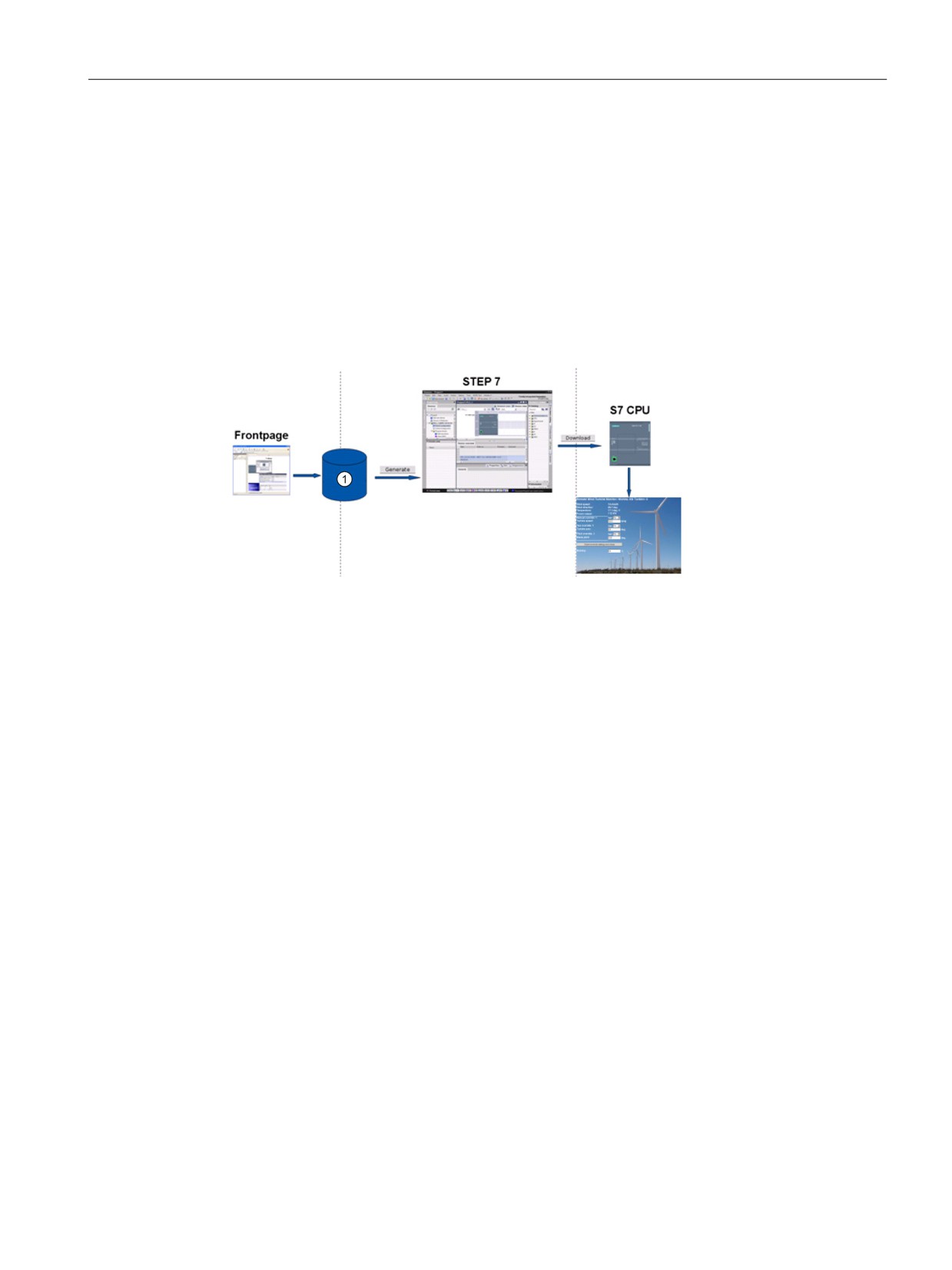
The S7-1200 Web server also provides the means for you to create your own application-
specific HTML pages that incorporate data from the PLC. Use the HTML editor of your
choice to create these pages, and then download them to the CPU from where they are
accessible from the standard Web pages.
① HTML files with embedded AWP commands
This process involves several tasks:
● Create the HTML pages with an HTML editor
● Include AWP commands in HTML comments in the HTML code: The AWP commands
are a fixed set of commands for accessing CPU information.
● Configure STEP 7 to read and process the HTML pages.
● Generate the program blocks from the HTML pages.
● Program STEP 7 to control the use of the HTML pages.
● Compile and download the program blocks to the CPU.
● Access the user-defined Web pages from your PC or mobile device.
You can use the software package of your choice to create your own HTML pages for use
with the Web server. Be sure that your HTML code is compliant to the HTML standards of
the W3C (World Wide Web Consortium). STEP 7 does not perform any verification of your
HTML syntax.
You can use a software package that lets you design in WYSIWYG or design layout mode,
but you need to be able to edit your HTML code in pure HTML form. Most Web authoring
tools provide this type of editing; otherwise, you can always use a simple text editor to edit
the HTML code. Include the following line in your HTML page to set the charset for the page
to UTF-8:
<meta http-equiv="content-type" content="text/html; charset=utf-8">
Also be sure to save the file from the editor in UTF-8 character encoding.
257
Web server for easy Internet connectivity
9.3 Easy to create user-defined web pages
You use STEP 7 to compile everything in your HTML pages into STEP 7 data blocks. These
data blocks consist of one control data block that directs the display of the Web pages and
one or more fragment data blocks that contain the compiled Web pages. Be aware that
extensive sets of HTML pages, particularly those with lots of images, require a significant
amount of load memory space for the fragment DBs. If the internal load memory of your CPU
is not sufficient for your user-defined Web pages, use a memory card to provide external
load memory.
To program your HTML code to use data from the S7-1200, you include AWP commands as
HTML comments. When finished, save your HTML pages to your PC and note the folder
path where you save them.
Note
The file size limit for HTML files containing AWP command is 64 kilobytes. You must keep
your file size below this limit.
Refreshing user-defined Web pages
User-defined Web pages do not automatically refresh. It is your choice whether to program
the HTML to refresh the page or not. For pages that display PLC data, refreshing periodically
keeps the data current. For HTML pages that serve as forms for data entry, refreshing can
interfere with the user entering data. If you want your entire page to automatically refresh,
you can add this line to your HTML header, where "10" is the number of seconds between
refreshes:
<meta http-equiv="Refresh" content="10">
You can also use JavaScript or other HTML techniques to control page or data refreshing.
For this, refer to documentation on HTML and JavaScript.
258
Web server for easy Internet connectivity
9.3 Easy to create user-defined web pages
9.3.2
Constraints specific to user-defined Web pages
The constraints for standard Web pages also apply to user-defined Web pages. In addition,
user-defined Web pages have some specific considerations.
Load memory space
Your user-defined Web pages become data blocks when you click "Generate blocks", which
require load memory space. If you have a memory card installed, you have up to the
capacity of your memory card as external load memory space for the user-defined Web
pages.
If you do not have a memory card installed, these blocks take up internal load memory
space, which is limited according to your CPU model.
You can check the amount of load memory space that is used and the amount that is
available from the Online and Diagnostic tools in STEP 7. You can also look at the properties
for the individual blocks that STEP 7 generates from your user-defined Web pages and see
the load memory consumption.
Note
If you need to reduce the space required for your user-defined Web pages, reduce your use
of images if applicable.
Quotation marks in text strings
Avoid using text strings that contain embedded single or double quotation marks in data
block tags that you use for any purpose in user-defined Web pages. Because HTML syntax
often uses single quotes or double quotes as delimiters, quotation marks within text strings
can break the display of user-defined Web pages.
For data block tags of type String that you use in user-defined Web pages, observe the
following rules:
● Do not enter single or double quotation marks in the data block tag string value in
STEP 7.
● Do not let the user program make assignments of strings containing quotes to these data
block tags.
259
Web server for easy Internet connectivity
9.3 Easy to create user-defined web pages
9.3.3
Configuration of a user-defined Web page
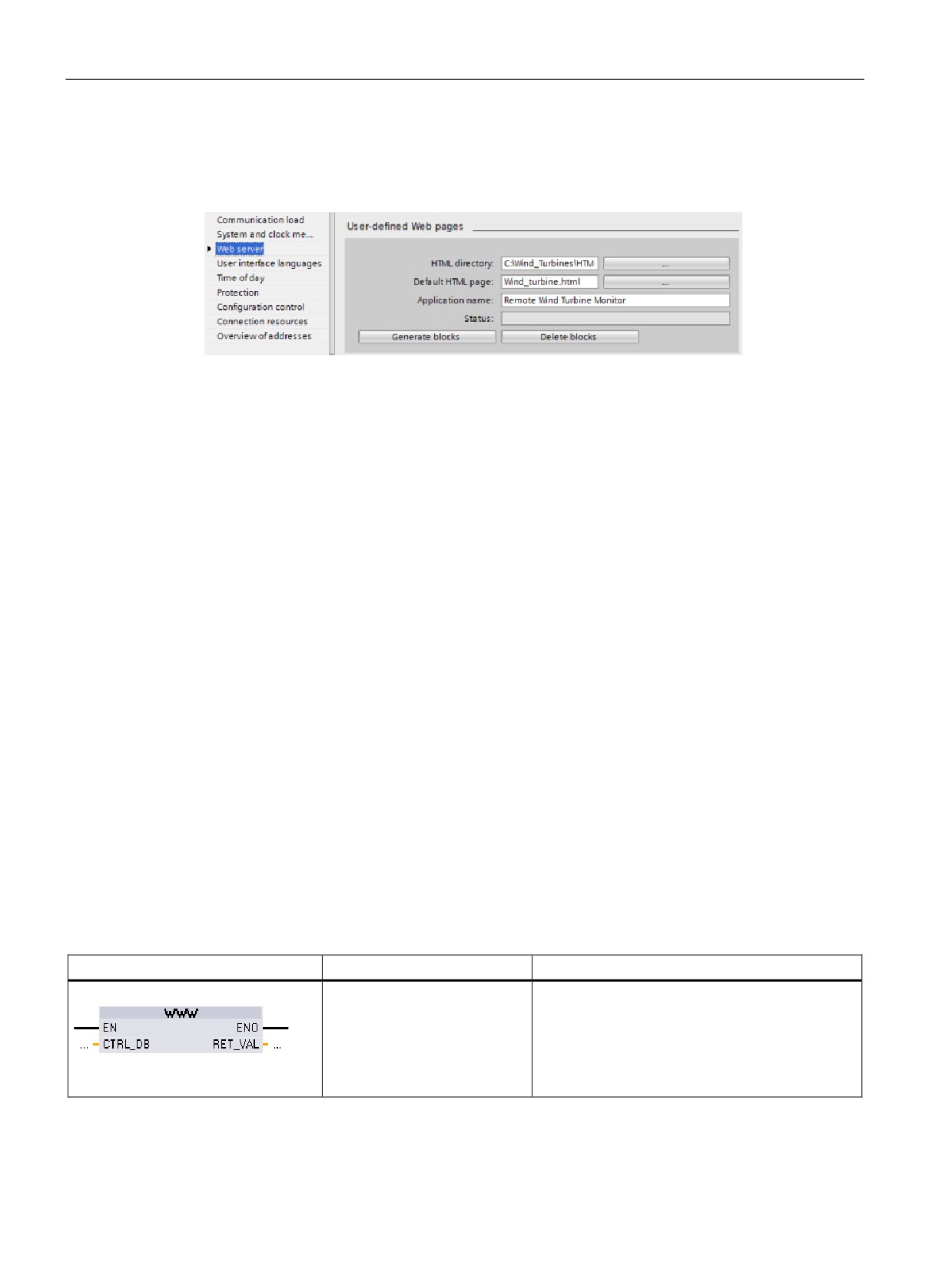
To configure the user-defined Web pages, edit the "Web server" properties of the CPU.
After you enable the Web server functionality, enter the following information:
● Name and the current location of the HTML default start page to generate the DBs for the
user-defined Web pages.
● Name for your application (optional). The application name is used to further
subcategorize or group web pages. When you provide an application name, the Web
server creates an URL for your user-defined page in the following format:
http[s]://ww.xx.yy.zz/awp/<application name>/<pagename>.html
● Filename extensions of files that contain AWP commands. By default, STEP 7 analyzes
files with .htm, .html, or .js extensions. If you have additional file extensions, append
them.
● Identification numbers for the control DB number and the initial fragment DB.
After configuring the Web server, click the "Generate blocks" button to generate the DBs
from the HTML pages. After you generate the DBs, your Web pages are a part of your user
program. The control data block for the operation of your Web pages, and the "fragment"
DBs contain all of the HTML pages.
9.3.4
Using the WWW instruction
The WWW instruction allows your user-defined Web pages to be accessible from the
standard Web pages. Your user program only has to execute the WWW instruction once to
enable access to the user-defined Web pages. You might, however, choose to make the
user-defined Web pages available only under certain circumstances. Your user program
could then call the WWW instruction according to your application requirements.
Table 9- 1
WWW instruction
LAD / FBD
SCL
Description
ret_val := #WWW(
Identifies the control DB to be used for the user-
defined Web pages.
ctrl_db:=_uint_in_);
The control data block is the input parameter to
the WWW instruction and specifies the content of
the pages as represented in the fragment data
blocks, as well as state and control information.
260
Web server for easy Internet connectivity
9.3 Easy to create user-defined web pages
Your user program typically uses the control DB directly as created by the "Generate blocks"
process, with no additional manipulation. However, the user program can set global
commands in the control DB to deactivate the web server, or to subsequently reactivate it.
Also, for user-defined pages that you create as manual fragment DBs, the user program
must control the behavior of these pages through a request table in the control DB, as
described in the S7-1200 Programmable Controller System Manual.
261
Web server for easy Internet connectivity
9.3 Easy to create user-defined web pages
262
Motion control is easy
10
The CPU provides motion control functionality for the operation of stepper motors and servo
motors with pulse interface. The motion control functionality takes over the control and
monitoring of the drives.
●
The "Axis" technology object configures the mechanical drive data, drive interface,
dynamic parameters, and other drive properties.
●
You configure the pulse and direction outputs of the CPU for controlling the drive.
●
Your user program uses the motion control instructions to control the axis and to initiate
motion tasks.
●
Use the PROFINET interface to establish the online connection between the CPU and the
programming device. In addition to the online functions of the CPU, additional
commissioning and diagnostic functions are available for motion control.
Note
Changes that you make to the motion control configuration and download in RUN mode
do not take effect until the CPU transitions from STOP to RUN mode.
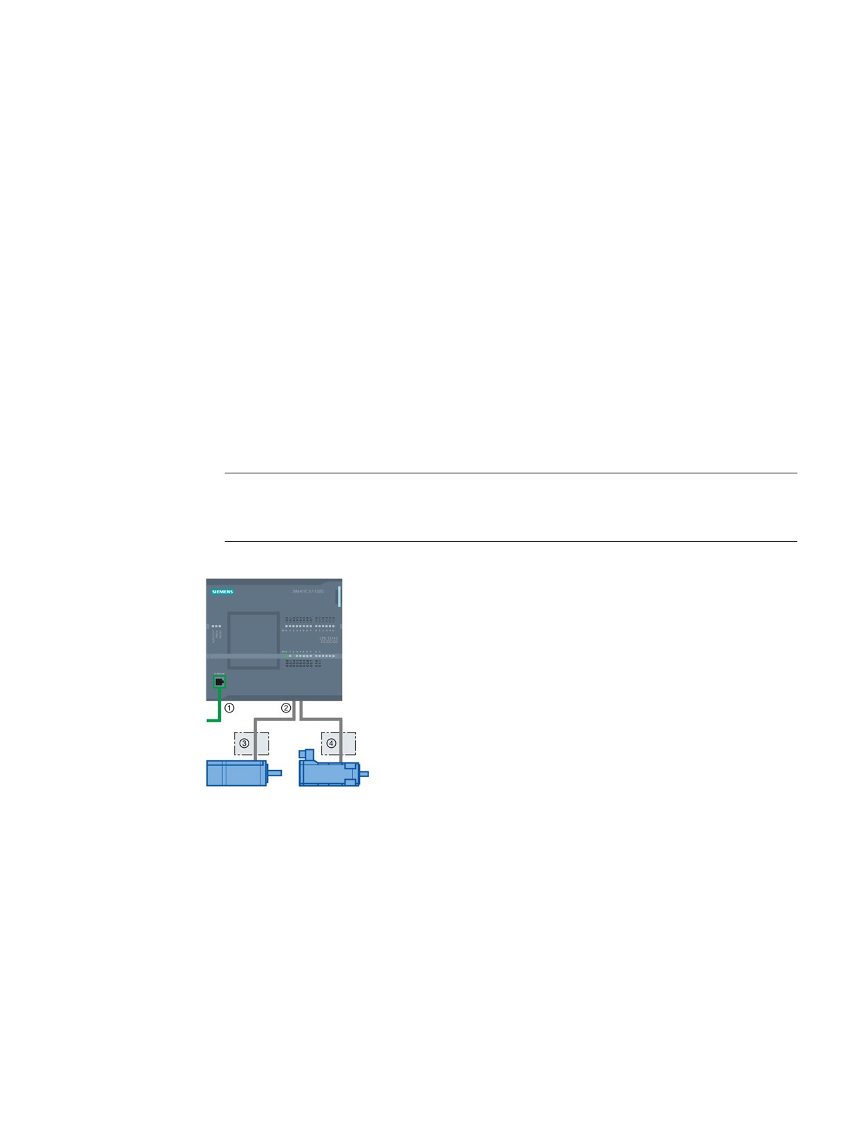
① PROFINET
② Pulse and direction outputs
③ Power section for stepper motor
④ Power section for servo motor
The DC/DC/DC variants of the CPU S7-1200 have onboard
outputs for direct control of drives. The relay variants of the
CPU require the signal board with DC outputs for drive con-
trol.
A signal board (SB) expands the onboard I/O to include a few additional I/O points. An SB
with two digital outputs can be used as pulse and direction outputs to control one motor. An
SB with four digital outputs can be used as pulse and direction outputs to control two motors.
Built-in relay outputs cannot be used as pulse outputs to control motors. Whether you use
onboard I/O or SB I/O or a combination of both, you can have a maximum number of four
pulse generators.
263
Motion control is easy
The four pulse generators have default I/O assignments; however, they can be configured to
any digital output on the CPU or SB. Pulse generators on the CPU cannot be assigned to
SMs or to distributed I/O.
Note
Pulse-train outputs cannot be used by other instructions in the user program
When you configure the outputs of the CPU or signal board as pulse generators (for use with
the PWM or motion control instructions), the corresponding output addresses no longer
control the outputs. If your user program writes a value to an output used as a pulse
generator, the CPU does not write that value to the physical output.
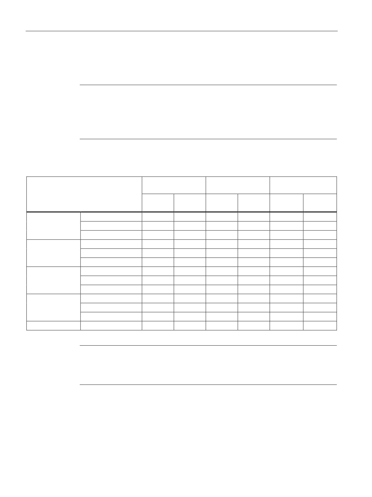
Table 10- 1 Maximum number of controllable drives
Type of CPU
Onboard I/O;
With an SB
With an SB
No SB installed
(2 x DC outputs)
(4 x DC outputs)
With direc-
Without
With direc-
Without
With direc-
Without
tion
direction
tion
direction
tion
direction
CPU 1211C
DC/DC/DC
2
4
3
4
4
4
AC/DC/RLY
0
0
1
2
2
4
DC/DC/RLY
0
0
1
2
2
4
CPU 1212C
DC/DC/DC
3
4
3
4
4
4
AC/DC/RLY
0
0
1
2
2
4
DC/DC/RLY
0
0
1
2
2
4
CPU 1214C
DC/DC/DC
4
4
4
4
4
4
AC/DC/RLY
0
0
1
2
2
4
DC/DC/RLY
0
0
1
2
2
4
CPU 1215C
DC/DC/DC
4
4
4
4
4
4
AC/DC/RLY
0
0
1
2
2
4
DC/DC/RLY
0
0
1
2
2
4
CPU 1217C
DC/DC/DC
4
4
4
4
4
4
Note
The maximum number of pulse generators is four.
Whether you use onboard I/O, SB I/O, or a combination of both, you can have a maximum
number of four pulse generators.
264
Motion control is easy
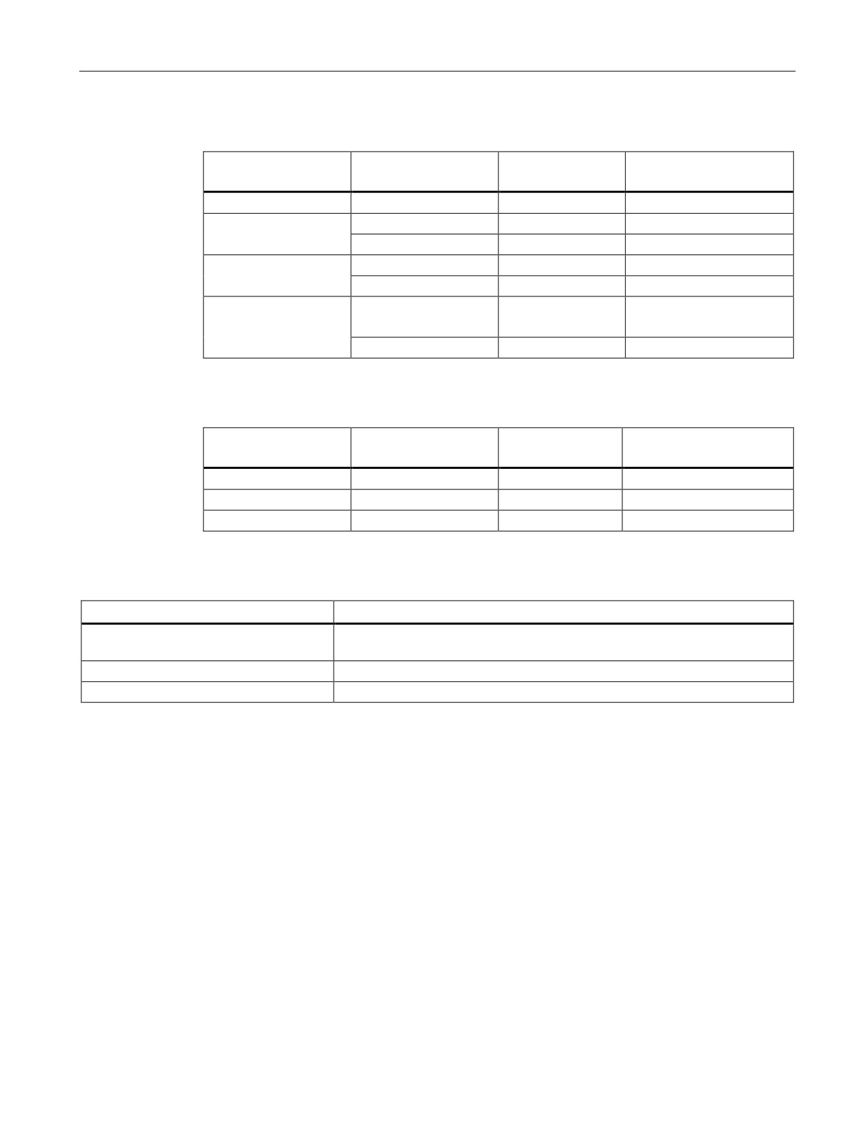
Table 10- 2 CPU output: maximum frequency
CPU
CPU output channel
Pulse and direction
A/B, quadrature, up/down,
output
and pulse/direction
1211C
Qa.0 to Qa.3
100 kHz
100 kHz
1212C
Qa.0 to Qa.3
100 kHz
100 kHz
Qa.4, Qa.5
20 kHz
20 kHz
1214C and 1215C
Qa.0 to Qa.3
100kHz
100kHz
Qa.4 to Qb.1
20 kHz
20 kHz
1217C
DQa.0 to DQa.3
1 MHz
1 MHz
(.0+, .0- to .3+, .3-)
DQa.4 to DQb.1
100 kHz
100 kHz
Table 10- 3 SB signal board output: maximum frequency (optional board)
SB signal board
SB output channel
Pulse and direction
A/B, quadrature, up/down,
output
and pulse/direction
SB 1222, 200 kHz
DQe.0 to DQe.3
200kHz
200 kHz
SB 1223, 200 kHz
DQe.0, DQe.1
200kHz
200 kHz
SB 1223
DQe.0, DQe.1
20 kHz
20 kHz
Table 10- 4 Limit frequencies of pulse outputs
Pulse output
Frequency
Onboard
4 PTO: 2 Hz ≤ f ≤ 1 MHz, 4 PTO: 2 Hz ≤ f ≤ 100 kHz, or any combination of
these values for 4 PTOs.1 2
Standard SB
2 Hz ≤ f ≤ 20 kHz
High-speed SBs
2 Hz ≤ f ≤ 200 kHz
1
See the table below for four possible CPU 1217C output speed combinations.
2
See the table below for four possible CPU 1211C, CPU 1212C, CPU 1214C, or CPU 1215C output speed combinations.
265
Motion control is easy
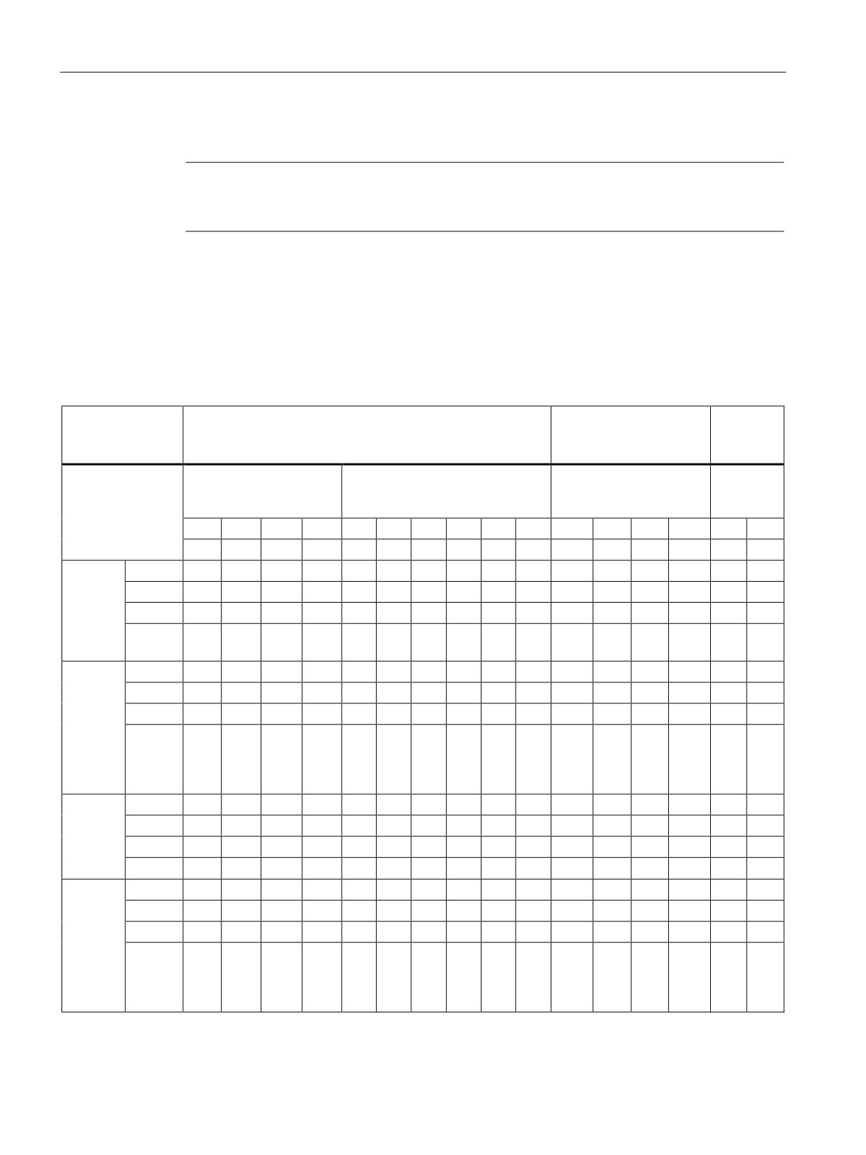
Example: CPU 1217C pulse output speed configurations
Note
The CPU 1217C can generate pulse outputs up to 1 MHz, using the onboard differential
outputs.
The examples below show four possible output speed combinations:
● Example 1: 4 - 1 MHz PTOs, no direction output
● Example 2: 1 - 1 MHz, 2 - 100 kHz, and 1 - 20 kHz PTOs, all with direction output
● Example 3: 4 - 200 kHz PTOs, no direction output
● Example 4: 2 - 100 kHz PTOs and 2 - 200 kHz PTOs, all with direction output
P = Pulse
CPU on-board outputs
High-speed SB outputs
Standard
SB out-
D = Direction
puts
1 MHz Outputs (Q)
100 kHz Outputs (Q)
200 kHz Outputs (Q)
20 kHz
Outputs
(Q)
0.0+
0.1+
0.2+
0.3+
0.4
0.5
0.6
0.7
1.0
1.1
4.0
4.1
4.2
4.3
4.0
4.1
0.0-
0.1-
0.2-
0.3-
Ex. 1:
PTO1
P
4 - 1
PTO2
P
MHz
PTO3
P
(no
direction
PTO4
P
output)
Ex. 2: 1 -
PTO1
P
D
1 MHz; 2
PTO2
P
D
- 100
PTO3
P
D
and 1 -
20 kHz
PTO4
P
D
(all with
direction
output)
Ex. 3:
PTO1
P
4 - 200
PTO2
P
kHz (no
PTO3
P
direction
output)
PTO4
P
Ex. 4:
PTO1
P
D
2 - 100
PTO2
P
D
kHz;
PTO3
P
D
2 - 200
kHz (all
PTO4
P
D
with
direction
output)
266
Motion control is easy
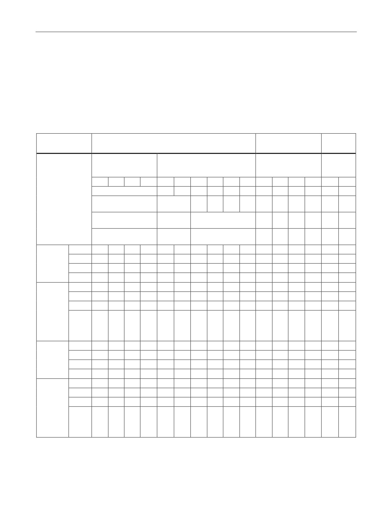
Example: CPU 1211C, CPU 1212C, CPU 1214C, and CPU 1215C pulse output speed configurations
The examples below show four possible output speed combinations:
● Example 1: 4 - 100 kHz PTOs, no direction output
● Example 2: 2 - 100 kHz PTOs and 2 - 20 kHz PTOs, all with direction output
● Example 3: 4 - 200 kHz PTOs, no direction output
● Example 4: 2 - 100 kHz PTOs and 2 - 200 kHz PTOs, all with direction output
P = Pulse
CPU on-board outputs
High-speed SB outputs
Low-speed
SB outputs
D = Direction
100 kHz Outputs (Q)
20 kHz Outputs (Q)
200 kHz Outputs (Q)
20 kHz
Outputs
(Q)
0.0
0.1
0.2
0.3
0.4
0.5
0.6
0.7
1.0
1.1
4.0
4.1
4.2
4.3
4.0
4.1
CPU 1211C
CPU 1212C
CPU
1212C
CPU 1214C
CPU
CPU 1214C
1214C
CPU 1215C
CPU
CPU 1215C
1215C
Ex. 1:
PTO1
P
4 - 100
PTO2
P
kHz (no
PTO3
P
direction
output)
PTO4
P
Ex. 2:
PTO1
P
D
2 - 100
PTO2
P
D
kHz;
PTO3
P
D
2 - 20
kHz (all
PTO4
P
D
with direc-
tion out-
put)
Ex. 3:
PTO1
P
4 - 200
PTO2
P
kHz (no
PTO3
P
direction
output)
PTO4
P
Ex. 4:
PTO1
P
D
2 - 100
PTO2
P
D
kHz;
PTO3
P
D
2 - 200
kHz (all
PTO4
P
D
with direc-
tion out-
put)
267
Motion control is easy
10.1 Phasing
10.1
Phasing
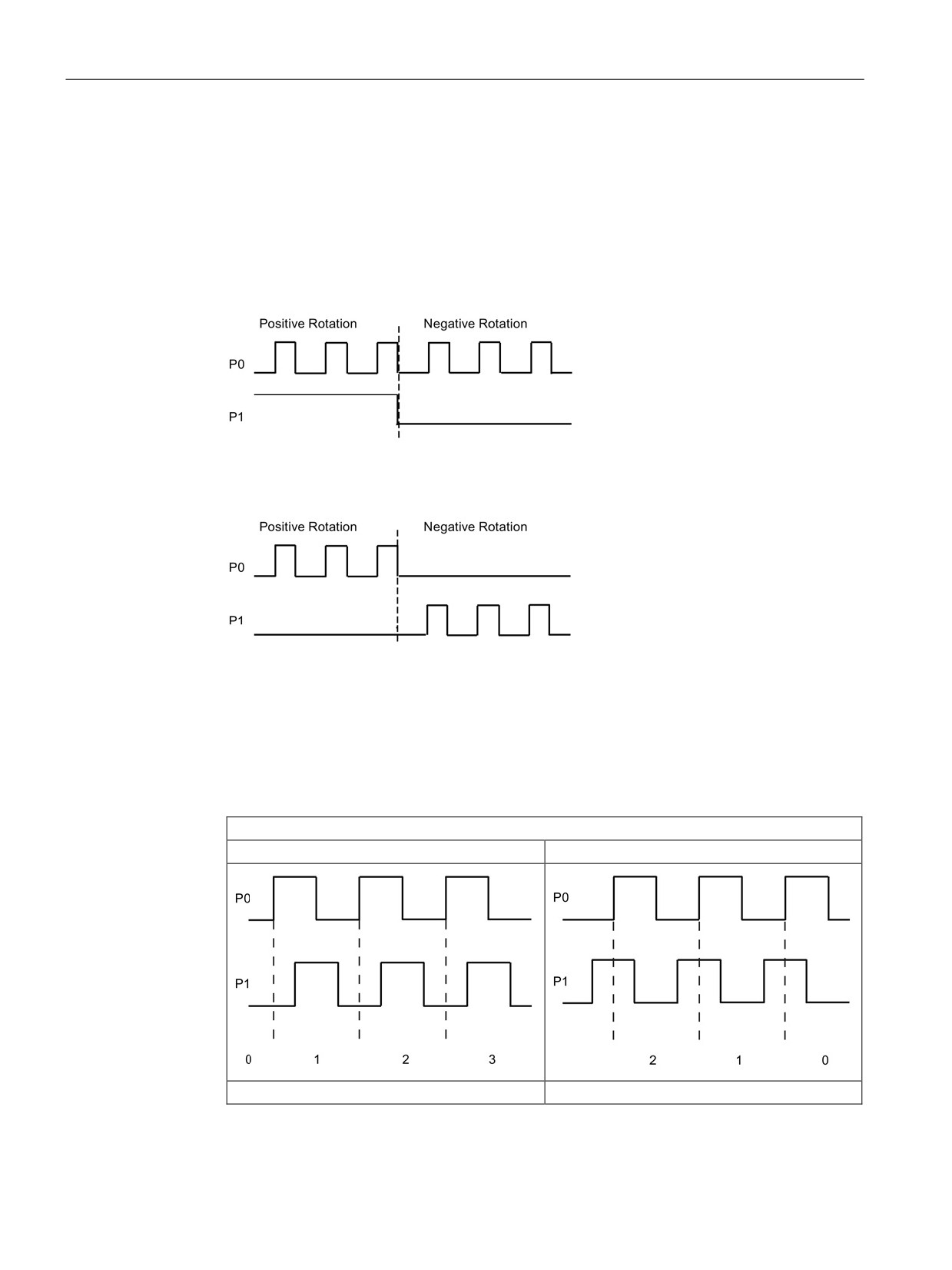
You have four options for the "Phasing" interface to the stepper/servo drive. These options
are as follows:
● PTO (pulse A and direction B): If you select a PTO (pulse A and direction B) option, then
one output (P0) controls the pulsing and one output (P1) controls the direction. P1 is high
(active) if pulsing is in the positive direction. P1 is low (inactive) if pulsing is in the
negative direction:
● PTO (count up A and count down B): If you select a PTO (count up A and count down B)
option, then one output (P0) pulses for positive directions and a different output (P1)
pulses for negative directions:
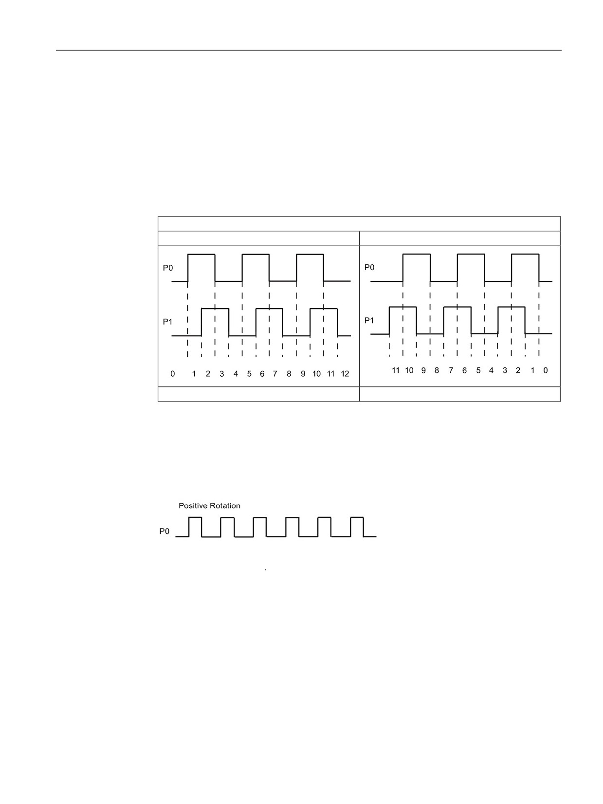
● PTO (A/B phase-shifted): If you select a PTO (A/B phase-shifted) option, then both
outputs pulse at the speed specified, but 90 degrees out-of-phase. It is a 1X
configuration, meaning one pulse is the amount of time between positive transitions of
P0. In this case, the direction is determined by which output transitions high first. P0
leads P1 for the positive direction. P1 leads P0 for the negative direction.
The number of pulses generated is based upon the number of 0 to 1 transitions of Phase
A. The phase relationship determines the direction of movement:
PTO (A/B phase-shifted)
Phase A leads phase B (positive movement)
Phase A lags phase B (negative movement)
Number of pulses
Number of pulses
268
Motion control is easy
10.1 Phasing
● PTO (A/B phase-shifted - fourfold): If you select a PTO (A/B phase-shifted - fourfold)
option, then both outputs pulse at the speed specified, but 90 degrees out-of-phase. The
fourfold is a 4X configuration, meaning one pulse is the transition of each output (both
positive and negative). In this case, the direction is determined by which output
transitions high first. P0 leads P1 for the positive direction. P1 leads P0 for the negative
direction.
Fourfold is based upon positive and negative transitions of both Phase A and Phase B.
You configure the number of transitions. The phase relationship (A leading B or B leading
A) determines the direction of movement.
PTO (A/B phase-shifted - fourfold)
Phase A leads phase B (positive movement)
Phase A lags phase B (negative movement)
Number of pulses
Number of pulses
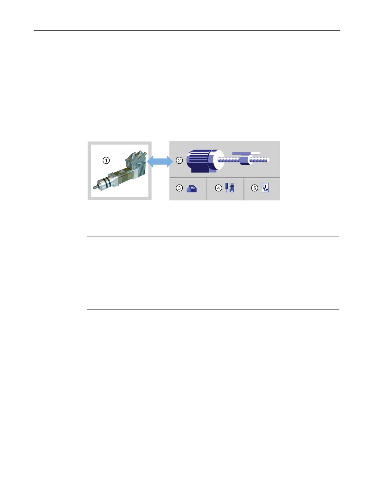
● PTO (pulse and direction (direction de-selected)): If you de-select the direction output in a
PTO (pulse and direction (direction de-selected)), then output (P0) controls the pulsing.
Output P1 is not used and is available for other program uses. Only positive motion
commands are accepted by the CPU in this mode. Motion control restricts you from
making illegal negative configurations when you select this mode. You can save an
output if your motion application is in one direction only. Single phase (one output) is
shown in the figure below (assuming positive polarity):
269

Motion control is easy
10.2 Configuring a pulse generator
10.2
Configuring a pulse generator
1.
Add a Technology object:
- In the Project tree, expand the node "Technology Objects" and select "Add new
object".
- Select the "Axis" icon (rename if required) and click "OK" to open the configuration
editor for the axis object.
- Display the "Select PTO for Axis Control" properties under the "Basic parameters" and
select the desired pulse.
Note
If the PTO has not been previously configured in the CPU Properties, the PTO is
configured to use one of the onboard outputs.
If you use an output signal board, then select the "Device configuration" button to go
to the CPU Properties. Under "Parameter assignment", in the "Pulse options",
configure the output source to a signal board output.
- Configure the remaining Basic and Extended parameters.
2.
Program your application: Insert the MC_Power instruction in a code block.
- For the Axis input, select the axis technology object that you created and configured.
- Setting the Enable input to TRUE allows the other motion instructions to function.
- Setting the Enable input FALSE cancels the other motion instructions.
Note
Include only one MC_Power instruction per axis.
3.
Insert the other motion instructions to produce the required motion.
Note
Configuring a pulse generator to signal board outputs: Select the "Pulse generators
(PTO/PWM)" properties for a CPU (in Device configuration) and enable a pulse generator.
Two pulse generators are available for each S7-1200 CPU V1.0, V2.0, V2.1, and V2.2.
S7-1200 CPU V3.0 and V4.0 CPUs have four pulse generators available. In this same
configuration area under "Pulse options", select Pulse generator used as: "PTO".
Note
The CPU calculates motion tasks in "slices" or segments of 10 ms. As one slice is being
executed, the next slice is waiting in the queue to be executed. If you interrupt the motion
task on an axis (by executing another new motion task for that axis), the new motion task
may not be executed for a maximum of 20 ms (the remainder of the current slice plus the
queued slice).
270
Motion control is easy
10.3 Open loop motion control
10.3
Open loop motion control
10.3.1
Configuring the axis
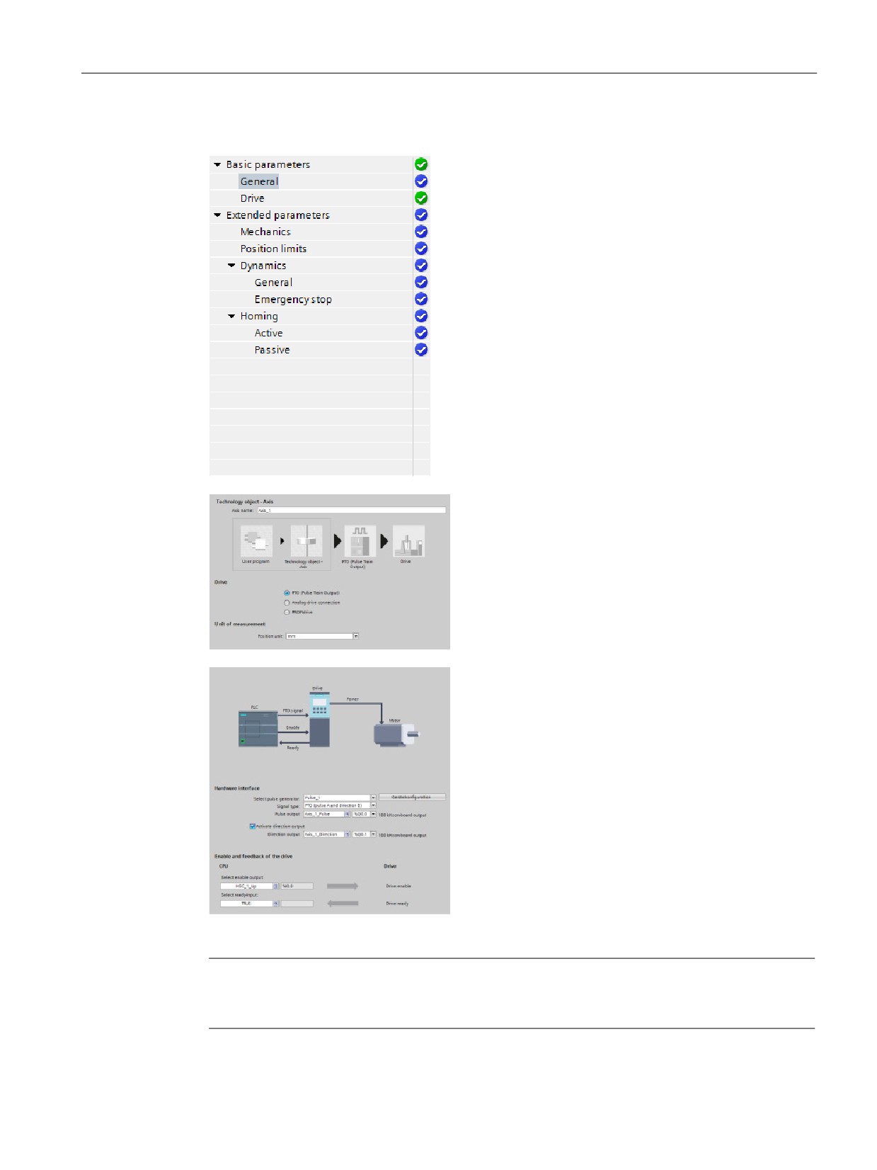
You connect the open loop axis on the PLC and the drive through a PTO (Pulse Train
Output).
STEP 7 provides the configuration tools, the commissioning tools, and the diagnostic tools
for the "Axis" technology object.
① Drive
④ Commissioning
② Technology object
⑤ Diagnostics
③ Configuration
Note
For CPU firmware releases V2.2 and earlier, the PTO requires the internal functionality of a
high-speed counter (HSC). This means the corresponding HSC cannot be used elsewhere.
The assignment between PTO and HSC is fixed. If PTO1 is activated, it will be connected to
HSC1. If PTO2 is activated, it will be connected to HSC2. You cannot monitor the current
value (for example, in ID1000) when pulses are occurring.
S7-1200 V3.0 and later CPUs do not have this restriction; all HSCs remain available for
program use when pulse outputs are configured in these CPUs.
271

Motion control is easy
10.3 Open loop motion control
Table 10- 5 STEP 7 tools for motion control
Tool
Description
Configuration
Configures the following properties of the "Axis" technology object:
• Selection of the PTO to be used and configuration of the drive interface
• Properties of the mechanics and the transmission ratio of the drive (or machine or system)
• Properties for position limits, dynamics, and homing
Save the configuration in the data block of the technology object.
Commissioning
Tests the function of your axis without having to create a user program. When the tool is started,
the control panel will be displayed. The following commands are available on the control panel:
• Enable and disable axis
• Move axis in jog mode
• Position axis in absolute and relative terms
• Home axis
• Acknowledge errors
The velocity and the acceleration / deceleration can be specified for the motion commands. The
control panel also shows the current axis status.
Diagnostics
Monitors of the current status and error information for the axis and drive.
272
Motion control is easy
10.3 Open loop motion control
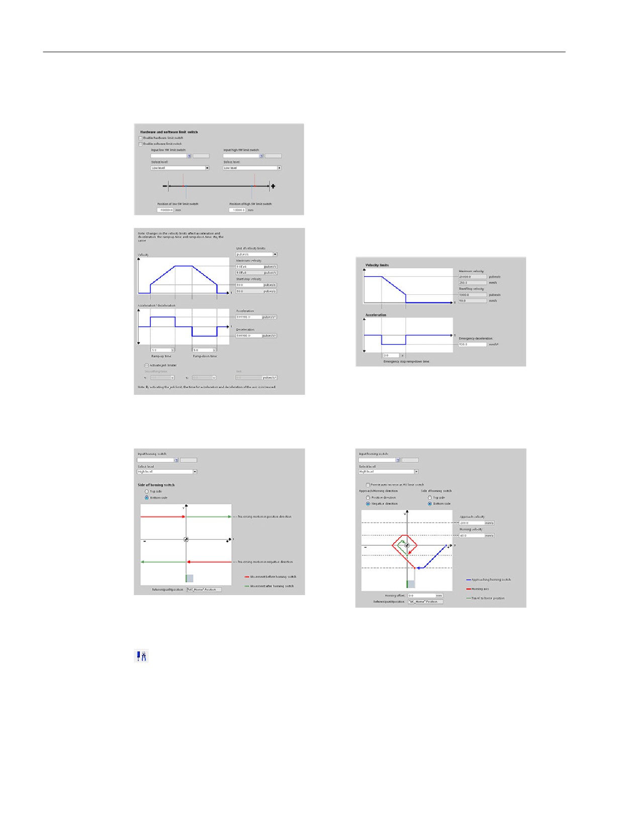
The tree selector for the PTO axis does not include
the Encoder, Modulo, Position monitoring, and
Control loop configuration menus.
After you create the technology object for the axis,
you configure the axis by defining the basic pa-
rameters, such as the PTO and the configuration of
the drive interface. You also configure the other
properties of the axis, such as position limits, dy-
namics, and homing.
Note
You may have to adapt the values of the input parameters of motion control instructions to
the new dimension unit in the user program.
273
Motion control is easy
10.3 Open loop motion control
Configure the properties for the drive signals, drive
mechanics, and position monitoring (hardware and
software limit switches).
You configure the motion dynamics and the behav-
ior of the emergency stop command.
You also configure the homing behavior (passive and active).
Use the "Commissioning" control panel to test the functionality independently from your user
program.
Click the "Startup" icon to commission the axis.
The control panel shows the current status of the axis. Not only can you enable and disable
the axis, but you can also test the positioning of the axis (both in absolute and relative terms)
and can specify the velocity, acceleration and deceleration. You can also test the homing
and jogging tasks. The control panel also allows you to acknowledge errors.
274
Motion control is easy
10.3 Open loop motion control
10.3.2
Commissioning
"Status and error bits" diagnostic function
Use the "Status and error bits" diagnostic function to monitor the most important status and
error messages for the axis. The diagnostic function display is available in online mode in
"Manual control" mode and in "Automatic control" when the axis is active.
Table 10- 6 Status of the axis
Status
Description
Enabled
The axis is enabled and ready to be controlled via motion control tasks.
(Tag of technology object: <Axis name>.StatusBits.Enable)
Homed
The axis is homed and is capable of executing absolute positioning tasks of motion control instruc-
tion "MC_MoveAbsolute". The axis does not have to be homed for relative homing. Special situa-
tions:
• During active homing, the status is FALSE.
• If a homed axis undergoes passive homing, the status is set to TRUE during passive homing.
(Tag of technology object: <Axis name>.StatusBits.HomingDone)
Error
An error has occurred in the "Axis" technology object. More information about the error is available
in automatic control at the ErrorID and ErrorInfo parameters of the motion control instructions. In
manual mode, the "Last error" field of the control panel displays detailed information about the
cause of error.
(Tag of technology object: <Axis name>.StatusBits.Error)
Control panel active
The "Manual control" mode was enabled in the control panel. The control panel has control priority
over the "Axis" technology object. The axis cannot be controlled from the user program.
(Tag of technology object: <Axis name>.StatusBits.ControlPanelActive)
Table 10- 7 Drive status
Status
Description
Drive ready
The drive is ready for operation.
(Tag of technology object: <Axis name>.StatusBits.DriveReady)
Error
The drive has reported an error after failure of its ready signal.
(Tag of technology object: <Axis name>.ErrorBits.DriveFault)
275
Motion control is easy
10.3 Open loop motion control
Table 10- 8 Status of the axis motion
Status
Description
Standstill
The axis is at a standstill.
(Tag of technology object: <Axis name>.StatusBits.StandStill)
Accelerating
The axis accelerates.
(Tag of technology object: <Axis name>.StatusBits.Acceleration)
Constant velocity
The axis travels at constant velocity.
(Tag of technology object: <Axis name>.StatusBits.ConstantVelocity)
Decelerating
The axis decelerates (slows down).
(Tag of technology object: <Axis name>.StatusBits.Deceleration)
Table 10- 9 Status of the motion mode
Status
Description
Positioning
The axis executes a positioning task of motion control instruction "MC_MoveAbsolute" or
"MC_MoveRelative" or of the control panel.
(Tag of technology object: <Axis name>.StatusBits.PositioningCommand)
Speed Command
The axis executes a task at set speed of motion control instruction "MC_MoveVelocity" or
"MC_MoveJog" or of the control panel.
(Tag of technology object: <Axis name>.StatusBits.SpeedCommand)
Homing
The axis executes a homing task of motion control instruction "MC_Home" or the control
panel.
(Tag of technology object: <Axis name>.StatusBits.Homing)
Table 10- 10 Error bits
Error
Description
Min software limit reached
The lower software limit switch has been reached.
(Tag of technology object: <Axis name>.ErrorBits.SwLimitMinReached)
Min software limit exceeded
The lower software limit switch has been exceeded.
(Tag of technology object: <Axis name>.ErrorBits.SwLimitMinExceeded)
Max software limit reached
The upper software limit switch has been reached.
(Tag of technology object: <Axis name>.ErrorBits.SwLimitMaxReached)
Max software limit exceeded
The upper software limit switch has been exceeded.
(Tag of technology object: <Axis name>.ErrorBits.SwLimitMaxExceeded)
Negative hardware limit
The lower hardware limit switch has been approached.
(Tag of technology object: <Axis name>.ErrorBits.HwLimitMin)
Positive hardware limit
The upper hardware limit switch has been approached.
(Tag of technology object: <Axis name>.ErrorBits.HwLimitMax)
PTO already used
A second axis is using the same PTO and is enabled with "MC_Power".
(Tag of technology object: <Axis name>.ErrorBits.HwUsed)
276
Motion control is easy
10.3 Open loop motion control
Error
Description
Configuration error
The "Axis" technology object was incorrectly configured or editable configuration data
were modified incorrectly during runtime of the user program.
(Tag of technology object: <Axis name>.ErrorBits.ConfigFault)
General Error
An internal error has occurred.
(Tag of technology object: <Axis name>.ErrorBits.SystemFault)
"Motion status" diagnostic function
Use the "Motion status" diagnostic function to monitor the motion status of the axis. The
diagnostic function display is available in online mode in "Manual control" mode and in
"Automatic control" when the axis is active.
Table 10- 11 Motion status
Status
Description
Target position
The "Target position" field indicates the current target position of an active positioning task of
motion control instruction "MC_MoveAbsolute" or "MC_MoveRelative" or of the control panel.
The value of the "Target position" is only valid during execution of a positioning task.
(Tag of technology object: <Axis name>.MotionStatus.TargetPosition)
Current position
The "Current position" field indicates the current axis position. If the axis is not homed, the
value indicates the position value relative to the enable position of the axis.
(Tag of technology object: <Axis name>.MotionStatus.Position)
Current velocity
The "Current velocity" field indicates the actual axis velocity.
(Tag of technology object: <Axis name>.MotionStatus.Velocity)
Table 10- 12 Dynamic limits
Dynamic limit
Description
Velocity
The "Velocity" field indicates the configured maximum velocity of the axis.
(Tag of technology object: <Axis name>.Config.DynamicLimits.MaxVelocity)
Acceleration
The "Acceleration" field indicates the currently configured acceleration of the axis.
(Tag of technology object: <Axis name>.Config.DynamicDefaults.Acceleration)
Deceleration
The "Deceleration" field indicates the currently configured deceleration of the axis.
(Tag of technology object: <Axis name>.Config.DynamicDefaults.Deceleration)
277
Motion control is easy
10.3 Open loop motion control
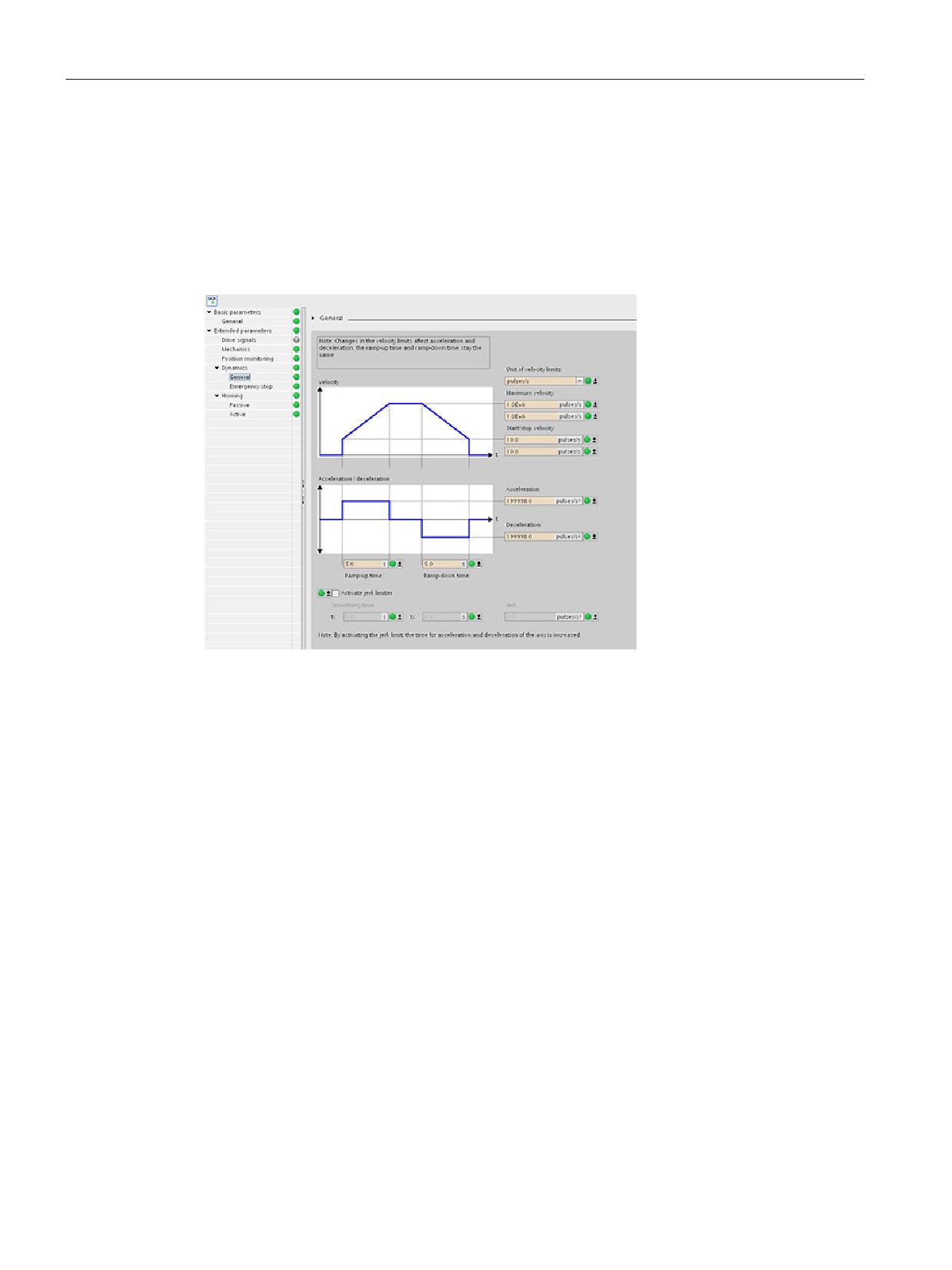
Motion start value control
You can edit the actual values of the Motion configuration parameters so that the behavior of
the process can be optimized in online mode.
Open the "Technology objects" for your motion control and its "Configuration" object. To
access the start value control, click the "eyeglasses icon" in the upper left corner of the
dialog:
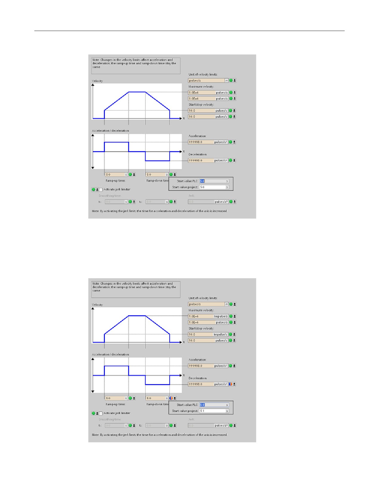
You can now change the value of any of your motion control configuration parameters as
shown in the figure below.
You can compare the actual value to the project (offline) start value and the PLC (online)
start value of each parameter. This is necessary to compare online/offline differences of the
Technology object data block (TO-DB) and to be informed about the values that will be used
as current values on the next Stop-to-Start transition of the PLC. In addition, a compare icon
gives a visual indication to help easily identify online/offline differences.
278
Motion control is easy
10.3 Open loop motion control
The figure above shows the Motion parameter screen with compare icons showing which
values are different between online and offline projects. A green icon indicates that the
values are the same; a blue/orange icon indicates that the values are different.
Additionally, click the parameter button with the downward arrow to open a small window
that shows the project (offline) start value and the PLC (online) start value of each
parameter.
279
Motion control is easy
10.4 Closed loop motion control
10.4
Closed loop motion control
10.4.1
Configuring the axis
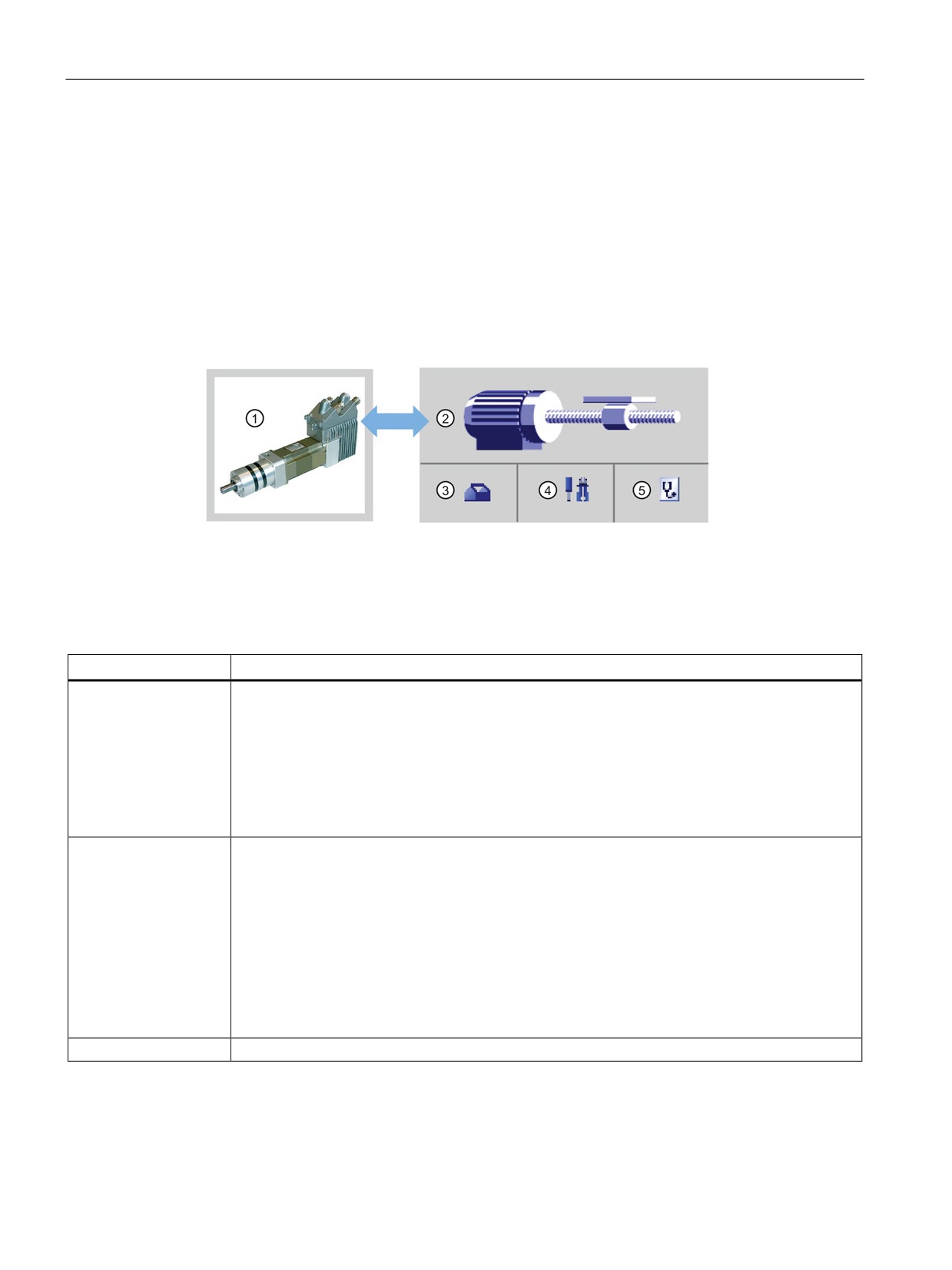
You connect the closed loop axis on the PLC and the drive through the analog drive or
PROFIdrive. The closed loop axis requires an encoder as well.
STEP 7 provides the configuration tools, the commissioning tools, and the diagnostic tools
for the "Axis" technology object.
① Drive
④ Commissioning
② Technology object
⑤ Diagnostics
③ Configuration
Table 10- 13 STEP 7 tools for closed loop motion control
Tool
Description
Configuration
Configures the following properties of the "Axis" technology object:
• Selection of the analog drive connection or PROFIdrive to be used and configuration of the
drive and encoder interface
• Properties of the mechanics and the transmission ratio of the drive and encoder (or machine
or system)
• Properties for position limits, dynamics, and homing
Save the configuration in the data block of the technology object.
Commissioning
Tests the function of your axis without having to create a user program. When the tool is started,
the control panel will be displayed. The following commands are available on the control panel:
• Enable and disable axis
• Move axis in jog mode
• Position axis in absolute and relative terms
• Home axis
• Acknowledge errors
The velocity and the acceleration / deceleration can be specified for the motion commands. The
control panel also shows the current axis status.
Diagnostics
Monitors of the current status and error information for the axis and drive.
280
Motion control is easy
10.4 Closed loop motion control
Note
You may have to adapt the values of the input parameters of motion control instructions to
the new dimension unit in the user program.
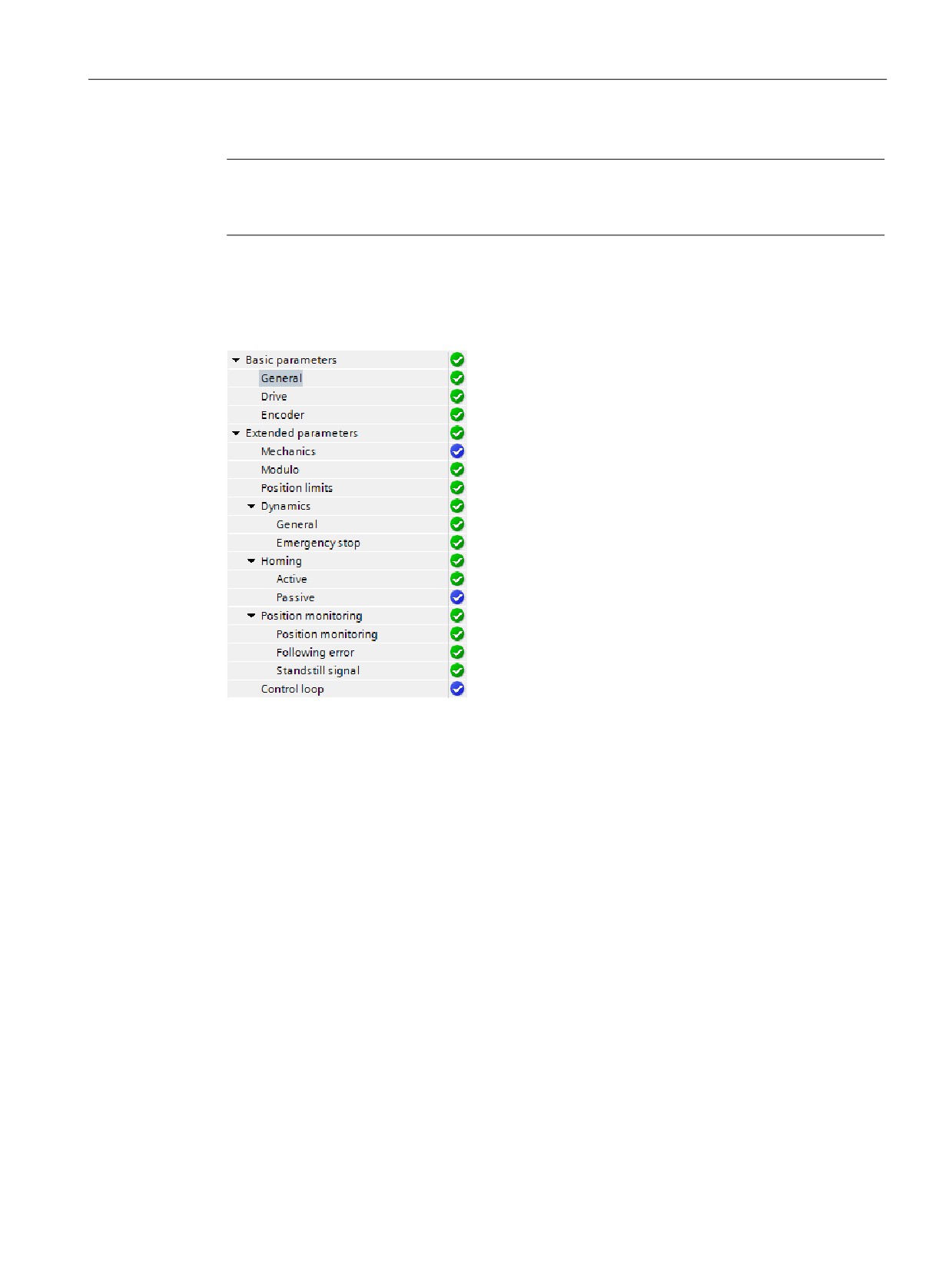
After you create the technology object for the axis, you configure the axis by defining the
basic parameters, either the Analog drive or the PROFIdrive connection and the
configuration of the drive and encoder.
The tree selector for the analog drive or
PROFIdrive connection includes the Encoder,
Modulo, Position monitoring, and Control loop con-
figuration menus.
281
Motion control is easy
10.4 Closed loop motion control
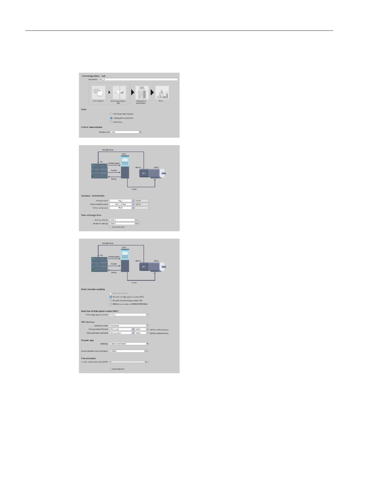
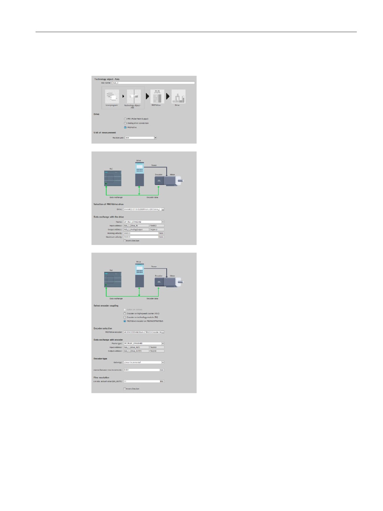
Analog drive connection configuration
In the General configuration dialog, you select the
following parameters:
• "Analog drive connection" radio button
• Unit of measurement
In the Drive configuration dialog, you select the
following parameters:
• Analog drive hardware outputs
• Data exchange drive velocities
In the Encoder configuration dialog, you select the
following parameters:
• Analog drive encoder coupling (for example, a
high-speed counter (HSC))
• HSC interface
• Encoder type
• Fine resolution
282
Motion control is easy
10.4 Closed loop motion control
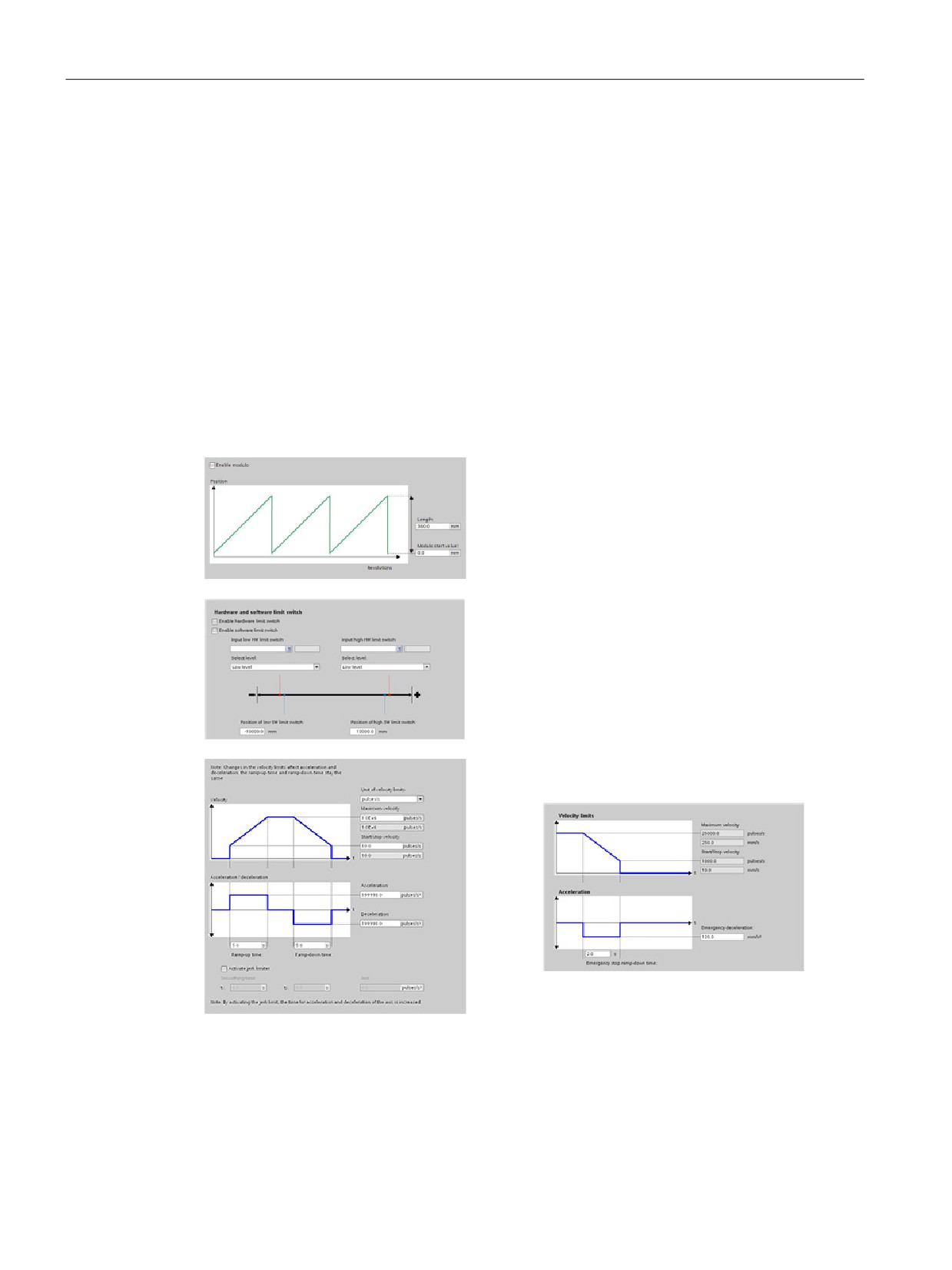
PROFIdrive configuration
In the General configuration dialog, you select the
following parameters:
• "PROFIdrive" radio button
• Unit of measurement
In the Drive configuration dialog, you select the
following parameters:
• PROFIdrive drive
• Data exchange with the drive
In the Encoder configuration dialog, you select the
following parameters:
• PROFIdrive encoder coupling (for example, a
PROFIdrive encoder on PROFINET)
• PROFIdrive encoder
• Data exchange with the encoder
• Encoder type
• Fine resolution
283
Motion control is easy
10.4 Closed loop motion control
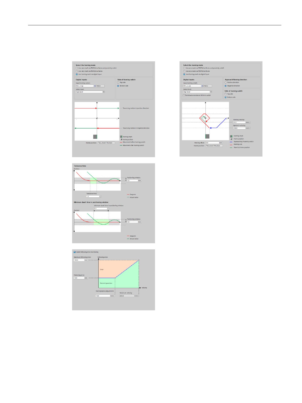
Extended parameters
You can also configure the following properties of the closed loop axis:
● Modulo
● Position limits
● Dynamics
● Homing
● Position monitoring
● Following error
● Standstill signal
● Control loop
Modulo: You can configure a "Modulo" axis to
move the load in a cyclic area which has a start
value/start position and a given length. If the posi-
tion of the load reaches the end of this area, it is
automatically set to the start value again. You ena-
ble the "Length" and "Modulo start value" fields
when you check the "Enable Modulo" check box.
Position limits: You can configure the properties for
the drive signals, drive mechanics, and position
monitoring (hardware and software limit switches).
Dynamics: You can configure the motion dynamics
and the behavior of the emergency stop command.
284
Motion control is easy
10.4 Closed loop motion control
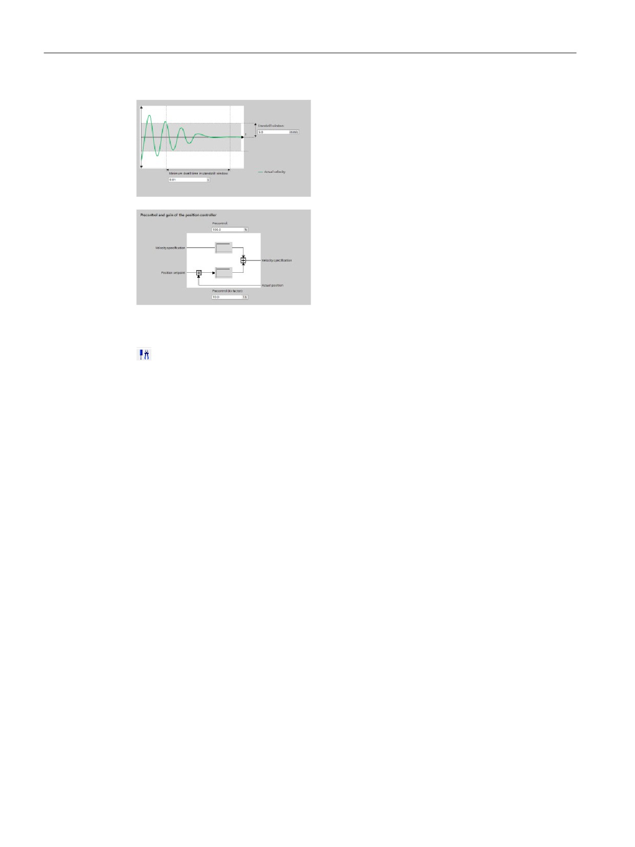
Homing: You can configure the homing behavior (passive and active).
"Positioning monitoring": You can configure
tolerance time as well as minimum dwell
time for the positioning window.
The system connects the following three
parameters directly with the axis TO-DB:
• Positioning window
• Tolerance time
• Minimum dwell time in positioning window
"Following error": You can configure the
difference of the allowed error distance over
a velocity range. You check the "Enable
following error monitoring" check box to acti-
vate following error. You can configure the
following the parameters:
• Maximum following error
• Following error
• Start dynamic adjustment
• Maximum velocity
285
Motion control is easy
10.4 Closed loop motion control
"Standstill signal": You can configure the
following the parameters:
• Minimum dwell time in standstill window
• Standstill window.
"Control loop": You can configure the veloci-
ty gain known as "Precontrol (Kv factor)".
Use the "Commissioning" control panel to test the functionality independently from your user
program.
Click the "Startup" icon to commission the axis.
The control panel shows the current status of the axis. Not only can you enable and disable
the axis, but you can also test the positioning of the axis (both in absolute and relative terms)
and can specify the velocity, acceleration and deceleration. You can also test the homing
and jogging tasks. The control panel also allows you to acknowledge errors.
286
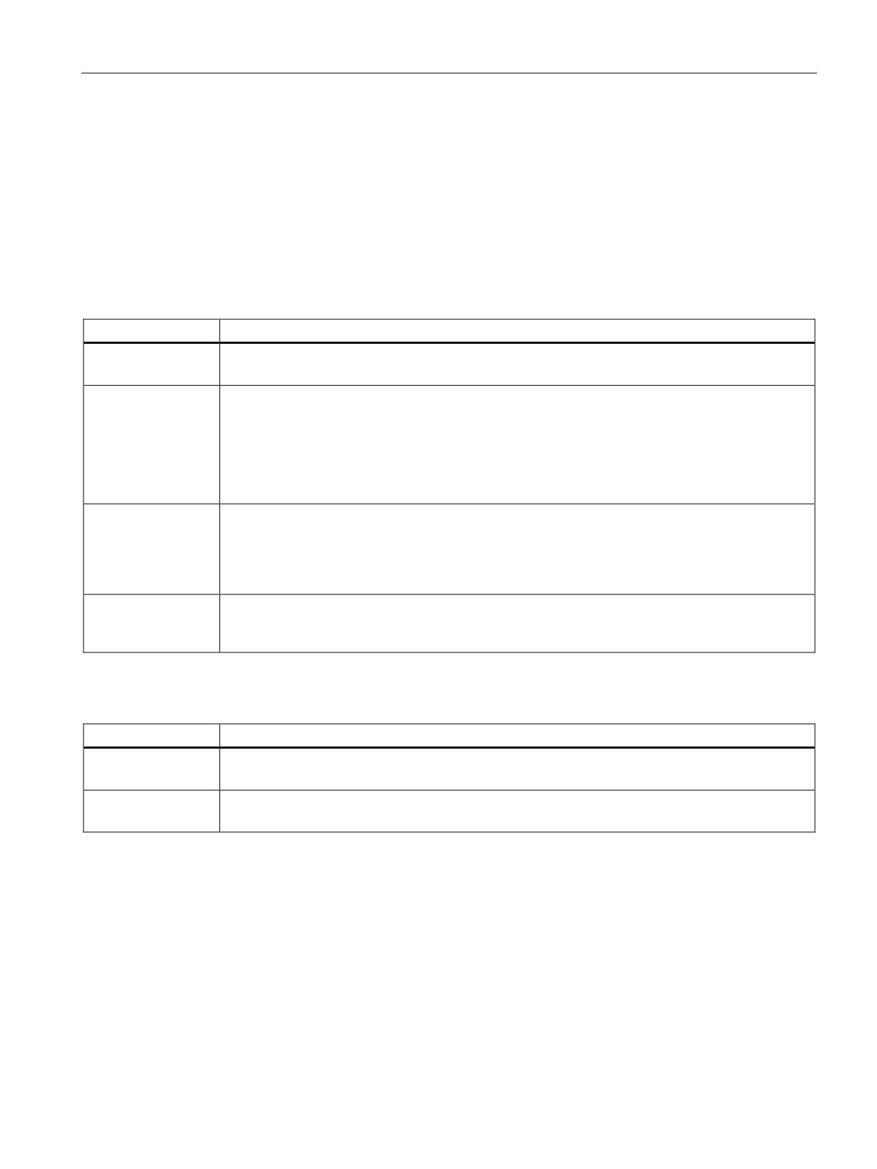
Motion control is easy
10.4 Closed loop motion control
10.4.2
Commissioning
"Status and error bits" diagnostic function
Use the "Status and error bits" diagnostic function to monitor the most important status and
error messages for the axis. The diagnostic function display is available in online mode in
"Manual control" mode and in "Automatic control" when the axis is active.
Table 10- 14 Status of the axis
Status
Description
Enabled
The axis is enabled and ready to be controlled via motion control tasks.
(Tag of technology object: <Axis name>.StatusBits.Enable)
Homed
The axis is homed and is capable of executing absolute positioning tasks of motion control instruc-
tion "MC_MoveAbsolute". The axis does not have to be homed for relative homing. Special situa-
tions:
• During active homing, the status is FALSE.
• If a homed axis undergoes passive homing, the status is set to TRUE during passive homing.
(Tag of technology object: <Axis name>.StatusBits.HomingDone)
Error
An error has occurred in the "Axis" technology object. More information about the error is available
in automatic control at the ErrorID and ErrorInfo parameters of the motion control instructions. In
manual mode, the "Last error" field of the control panel displays detailed information about the
cause of error.
(Tag of technology object: <Axis name>.StatusBits.Error)
Control panel active
The "Manual control" mode was enabled in the control panel. The control panel has control priority
over the "Axis" technology object. The axis cannot be controlled from the user program.
(Tag of technology object: <Axis name>.StatusBits.ControlPanelActive)
Table 10- 15 Drive status
Status
Description
Drive ready
The drive is ready for operation.
(Tag of technology object: <Axis name>.StatusBits.DriveReady)
Error
The drive has reported an error after failure of its ready signal.
(Tag of technology object: <Axis name>.ErrorBits.DriveFault)
287
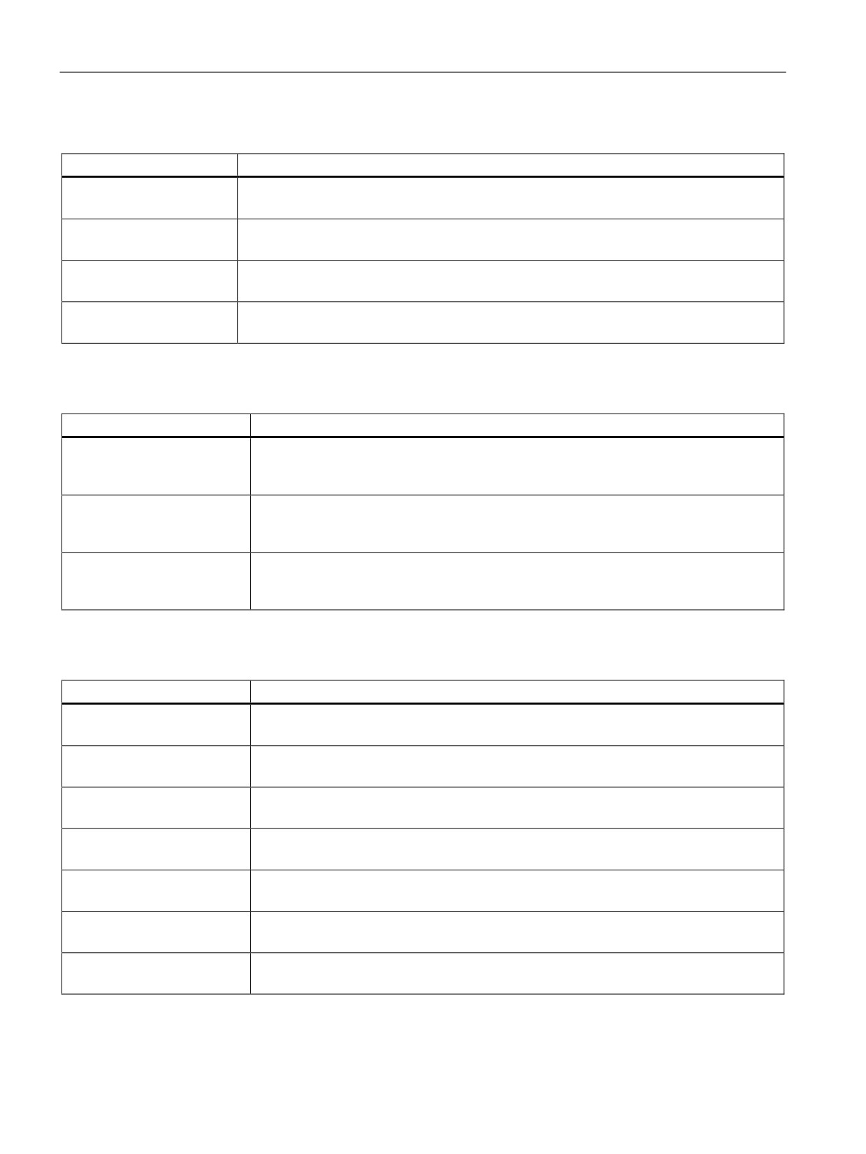
Motion control is easy
10.4 Closed loop motion control
Table 10- 16 Status of the axis motion
Status
Description
Standstill
The axis is at a standstill.
(Tag of technology object: <Axis name>.StatusBits.StandStill)
Accelerating
The axis accelerates.
(Tag of technology object: <Axis name>.StatusBits.Acceleration)
Constant velocity
The axis travels at constant velocity.
(Tag of technology object: <Axis name>.StatusBits.ConstantVelocity)
Decelerating
The axis decelerates (slows down).
(Tag of technology object: <Axis name>.StatusBits.Deceleration)
Table 10- 17 Status of the motion mode
Status
Description
Positioning
The axis executes a positioning task of motion control instruction "MC_MoveAbsolute" or
"MC_MoveRelative" or of the control panel.
(Tag of technology object: <Axis name>.StatusBits.PositioningCommand)
Speed Command
The axis executes a task at set speed of motion control instruction "MC_MoveVelocity" or
"MC_MoveJog" or of the control panel.
(Tag of technology object: <Axis name>.StatusBits.SpeedCommand)
Homing
The axis executes a homing task of motion control instruction "MC_Home" or the control
panel.
(Tag of technology object: <Axis name>.StatusBits.Homing)
Table 10- 18 Error bits
Error
Description
Min software limit reached
The lower software limit switch has been reached.
(Tag of technology object: <Axis name>.ErrorBits.SwLimitMinReached)
Min software limit exceeded
The lower software limit switch has been exceeded.
(Tag of technology object: <Axis name>.ErrorBits.SwLimitMinExceeded)
Max software limit reached
The upper software limit switch has been reached.
(Tag of technology object: <Axis name>.ErrorBits.SwLimitMaxReached)
Max software limit exceeded
The upper software limit switch has been exceeded.
(Tag of technology object: <Axis name>.ErrorBits.SwLimitMaxExceeded)
Negative hardware limit
The lower hardware limit switch has been approached.
(Tag of technology object: <Axis name>.ErrorBits.HwLimitMin)
Positive hardware limit
The upper hardware limit switch has been approached.
(Tag of technology object: <Axis name>.ErrorBits.HwLimitMax)
PTO already used
A second axis is using the same PTO and is enabled with "MC_Power".
(Tag of technology object: <Axis name>.ErrorBits.HwUsed)
288
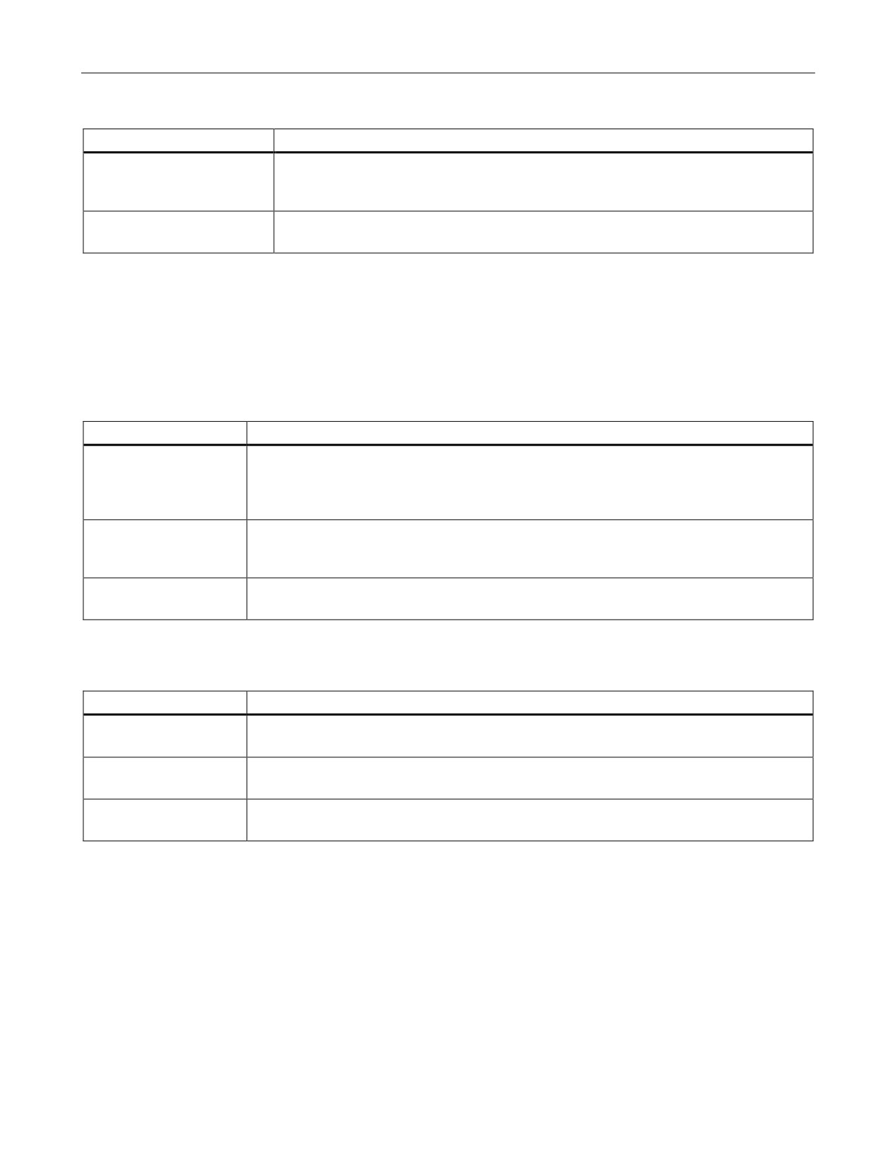
Motion control is easy
10.4 Closed loop motion control
Error
Description
Configuration error
The "Axis" technology object was incorrectly configured or editable configuration data
were modified incorrectly during runtime of the user program.
(Tag of technology object: <Axis name>.ErrorBits.ConfigFault)
General Error
An internal error has occurred.
(Tag of technology object: <Axis name>.ErrorBits.SystemFault)
"Motion status" diagnostic function
Use the "Motion status" diagnostic function to monitor the motion status of the axis. The
diagnostic function display is available in online mode in "Manual control" mode and in
"Automatic control" when the axis is active.
Table 10- 19 Motion status
Status
Description
Target position
The "Target position" field indicates the current target position of an active positioning task of
motion control instruction "MC_MoveAbsolute" or "MC_MoveRelative" or of the control panel.
The value of the "Target position" is only valid during execution of a positioning task.
(Tag of technology object: <Axis name>.MotionStatus.TargetPosition)
Current position
The "Current position" field indicates the current axis position. If the axis is not homed, the
value indicates the position value relative to the enable position of the axis.
(Tag of technology object: <Axis name>.MotionStatus.Position)
Current velocity
The "Current velocity" field indicates the actual axis velocity.
(Tag of technology object: <Axis name>.MotionStatus.Velocity)
Table 10- 20 Dynamic limits
Dynamic limit
Description
Velocity
The "Velocity" field indicates the configured maximum velocity of the axis.
(Tag of technology object: <Axis name>.Config.DynamicLimits.MaxVelocity)
Acceleration
The "Acceleration" field indicates the currently configured acceleration of the axis.
(Tag of technology object: <Axis name>.Config.DynamicDefaults.Acceleration)
Deceleration
The "Deceleration" field indicates the currently configured deceleration of the axis.
(Tag of technology object: <Axis name>.Config.DynamicDefaults.Deceleration)
289
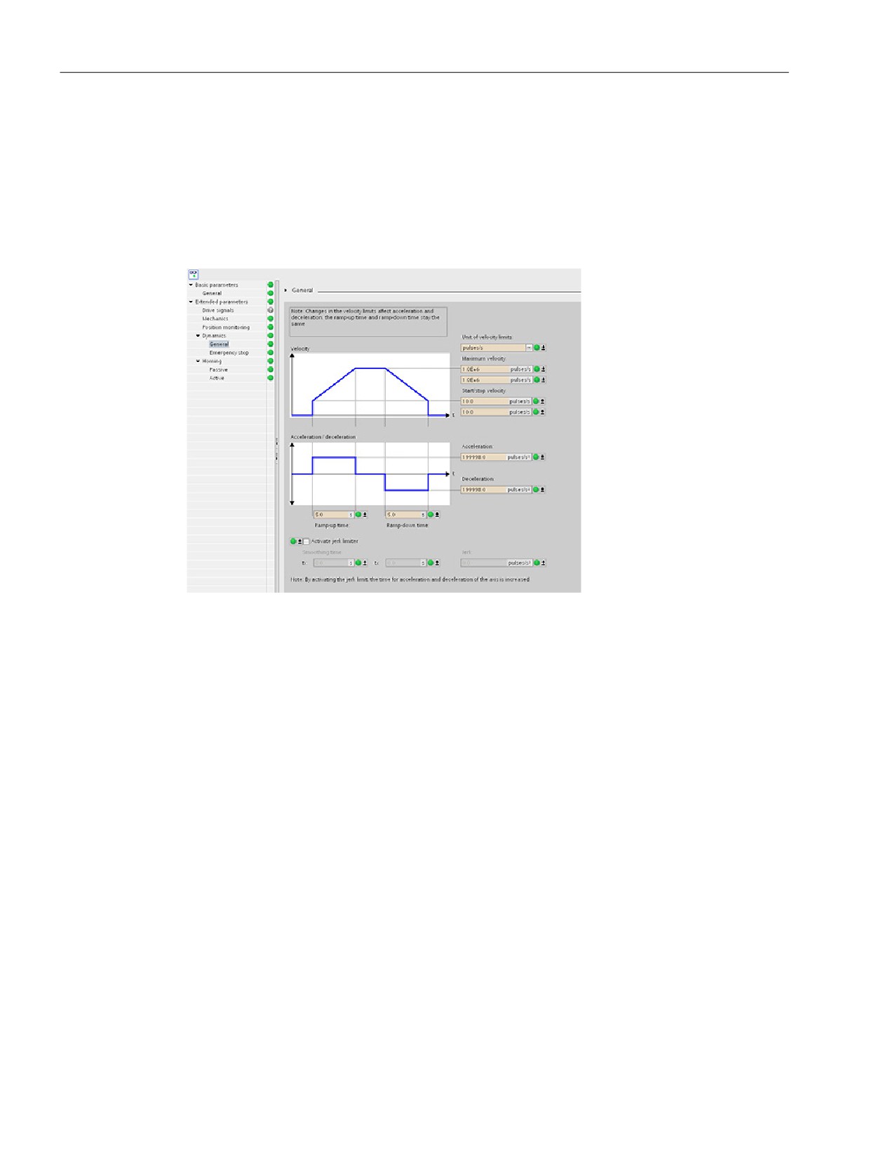
Motion control is easy
10.4 Closed loop motion control
Motion start value control
You can edit the actual values of the Motion configuration parameters so that the behavior of
the process can be optimized in online mode.
Open the "Technology objects" for your motion control and its "Configuration" object. To
access the start value control, click the "eyeglasses icon" in the upper left corner of the
dialog:
290
Motion control is easy
10.4 Closed loop motion control
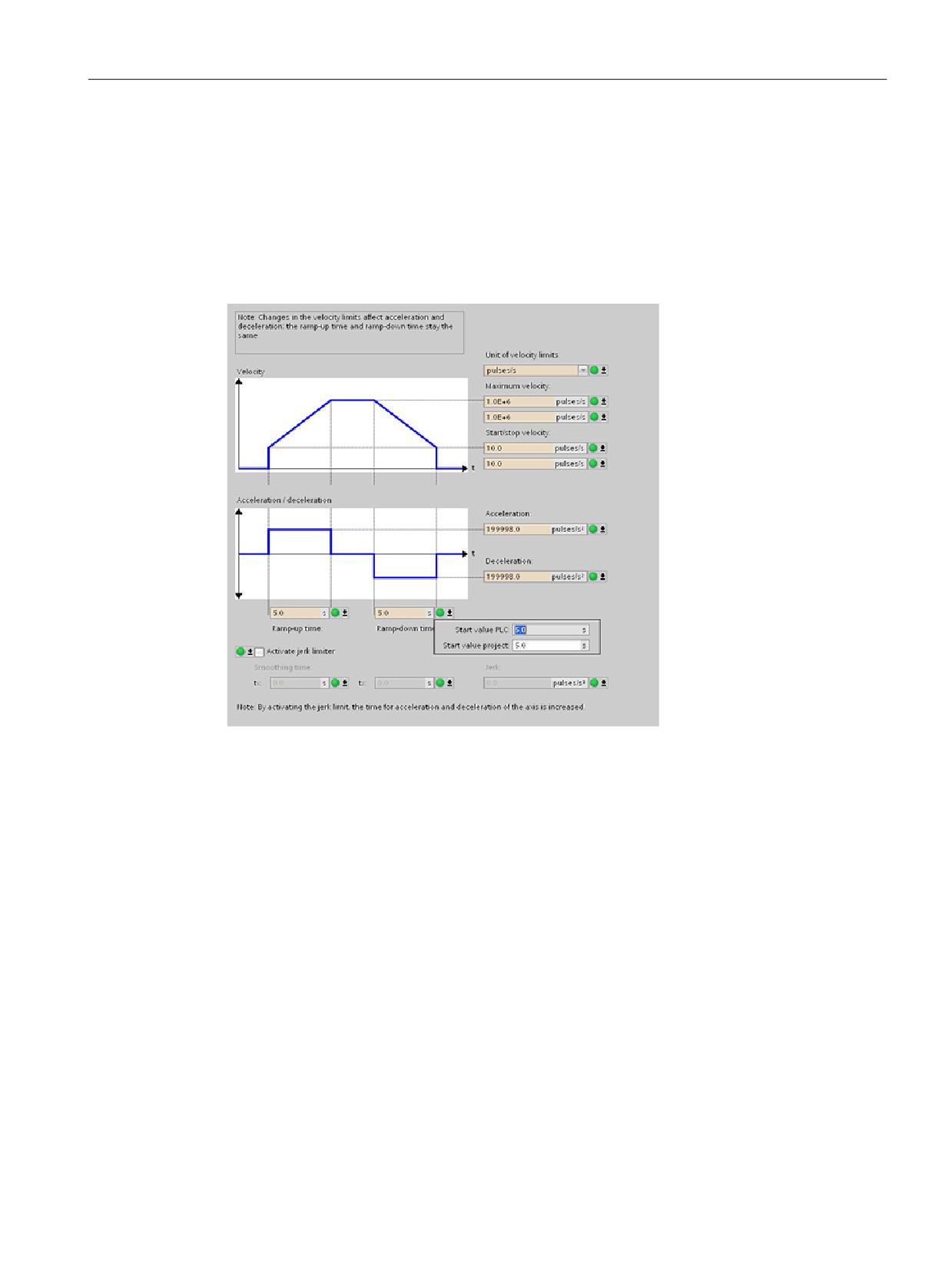
You can now change the value of any of your motion control configuration parameters as
shown in the figure below.
You can compare the actual value to the project (offline) start value and the PLC (online)
start value of each parameter. This is necessary to compare online/offline differences of the
Technology object data block (TO-DB) and to be informed about the values that will be used
as current values on the next Stop-to-Start transition of the PLC. In addition, a compare icon
gives a visual indication to help easily identify online/offline differences.
The figure above shows the Motion parameter screen with compare icons showing which
values are different between online and offline projects. A green icon indicates that the
values are the same; a blue/orange icon indicates that the values are different.
291
Motion control is easy
10.4 Closed loop motion control
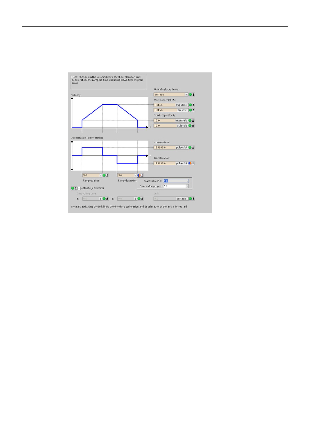
Additionally, click the parameter button with the downward arrow to open a small window
that shows the project (offline) start value and the PLC (online) start value of each
parameter.
292
Motion control is easy
10.5 Configuring the TO_CommandTable_PTO
10.5
Configuring the TO_CommandTable_PTO
You can configure a MC_CommandTable instruction using the Technology objects. The
following example demonstrates how this is done.
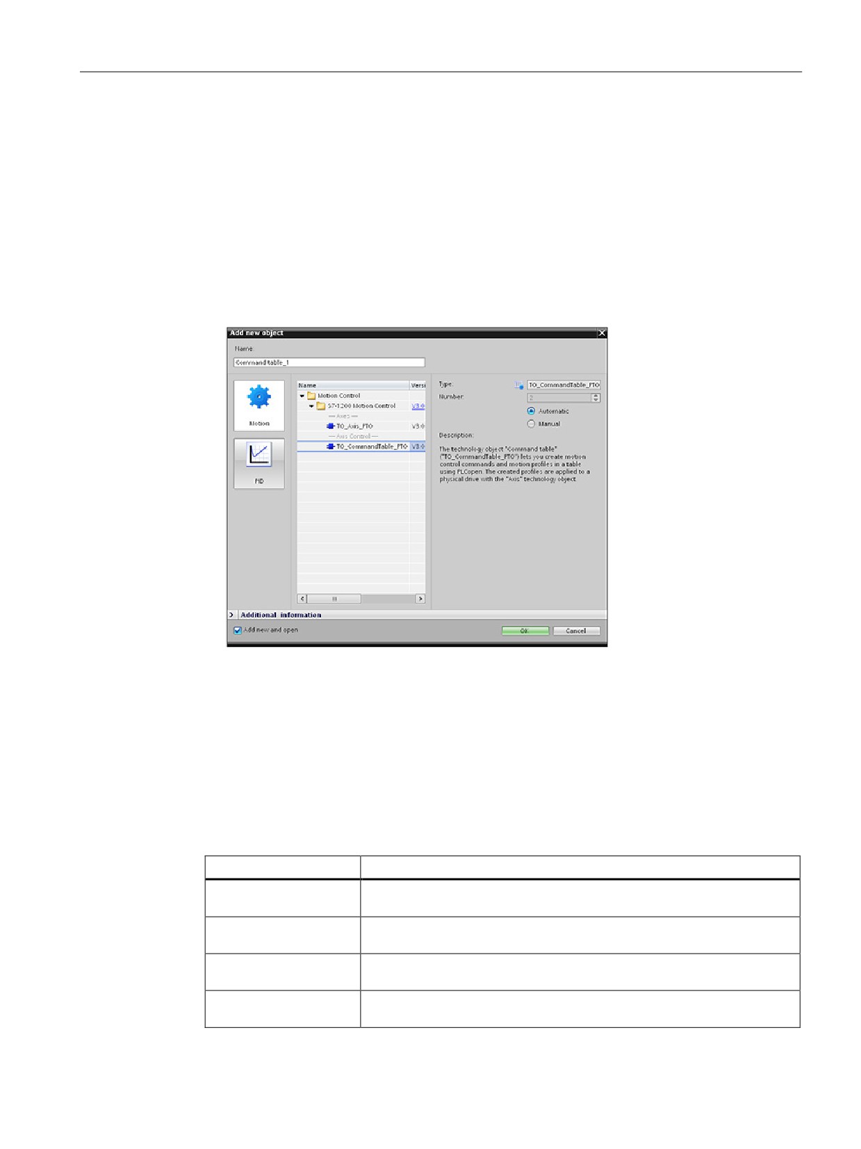
Adding a Technology object
1. In the Project tree, expand the node "Technology Objects" and select "Add new object".
2. Select the "CommandTable" icon (rename if required), and click "OK" to open the
configuration editor for the CommandTable object.
Planning the steps for your application
You can create the desired movement sequence in the "Command Table" configuration
window, and check the result against the graphic view in the trend diagram.
You can select the command types that are to be used for processing the command table.
Up to 32 steps can be entered. The commands are processed in sequence, easily producing
a complex motion profile.
Table 10- 21 MC_CommandTable command types
Command type
Description
Empty
The empty serves as a placeholder for any commands to be added. The
empty entry is ignored when the command table is processed
Halt
Pause axis.
Note: The command only takes place after a "Velocity setpoint" command.
Positioning Relative
Positions the axis based upon distance. The command moves the axis by
the given distance and velocity.
Positioning Absolute
Positions the axis based upon location. The command moves the axis to
the given location, using the velocity specified.
293
Motion control is easy
10.5 Configuring the TO_CommandTable_PTO
Command type
Description
Velocity setpoint
Moves the axis at the given velocity.
Wait
Waits until the given period is over. "Wait" does not stop an active travers-
ing motion.
Separator
Adds a "Separator" line above the selected line. The separator line allows
more than one profile to be defined in a single command table.
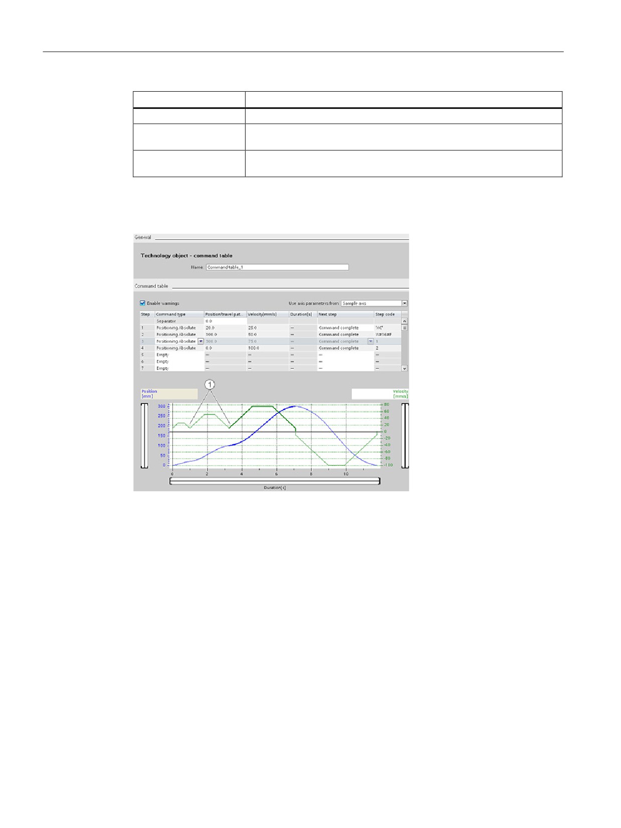
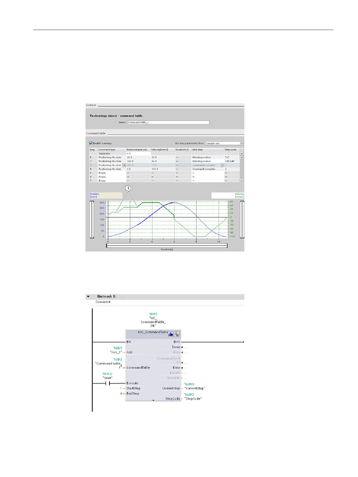
In the figure below, "Command complete" is used as the transition to the next step. This type
of transition allows your device to decelerate to the start/stop speed and then accelerate
once again at the start of the next step.
① Axis decelerates to the start/stop speed between steps.
294
Motion control is easy
10.5 Configuring the TO_CommandTable_PTO
In the figure below, "Blending motion" is used as the transition to the next step. This type of
transition allows your device to maintain its velocity into the start of the next step, resulting in
a smooth transition for the device from one step to the next. Using blending can shorten the
total time required for a profile to execute completely. Without blending, this example takes
seven seconds to run. With blending, the execution time is reduced by one second to a total
of six seconds.
① Axis continues to move and accelerates or decelerates to the next step velocity, saving time and
mechanical wear.
The operation of your CommandTable is controlled by an MC_CommandTable instruction,
as shown below:
295

Motion control is easy
10.6 Operation of motion control for S7-1200
10.6
Operation of motion control for S7-1200
10.6.1
CPU outputs used for motion control
The CPU provides four pulse output generators. Each pulse output generator provides one
pulse output and one direction output for controlling a stepper motor drive or a servo motor
drive with pulse interface. The pulse output provides the drive with the pulses required for
motor motion. The direction output controls the travel direction of the drive.
The PTO output generates a square wave output of variable frequency. Pulse generation is
controlled by configuration and execution information supplied through H/W configuration
and/or SFCs/SFBs.
Based upon the user’s selection while the CPU is in RUN mode, either the values stored in
the image register or the pulse generator outputs drive the digital outputs. In STOP mode,
the PTO generator does not control the outputs.
Onboard CPU outputs and outputs of a signal board can be used as pulse and direction
outputs. You select between onboard CPU outputs and outputs of the signal board during
device configuration under Pulse generators (PTO/PWM) on the "Properties" tab. Only PTO
(Pulse Train Output) applies to motion control.
The table below shows the default I/O assignments; however, the four pulse generators can
be configured to any digital output.
Note
Pulse-train outputs cannot be used by other instructions in the user program.
When you configure the outputs of the CPU or signal board as pulse generators (for use with
the PWM or motion control instructions), the corresponding output addresses no longer
control the outputs. If your user program writes a value to an output used as a pulse
generator, the CPU does not write that value to the physical output.
Note
PTO direction outputs can be freed for use elsewhere in your program.
Each PTO requires the assignment of two outputs: one as a pulse output and one as a
direction output. You can use just the pulse output and not the direction output. You can then
free the direction output for other purposes in your user program. The output cannot be used
for both the PTO direction output and in the user program, simultaneously.
296
Motion control is easy
10.6 Operation of motion control for S7-1200
Table 10- 22 Default address assignments of the pulse and direction outputs
Usage of outputs for motion control
Pulse
Direction
PTO1
Built-in I/O
Q0.0
Q0.1
SB I/O
Q4.0
Q4.1
PTO2
Built-in I/O
Q0.2
Q0.3
SB I/O
Q4.2 1
Q4.3 1
PTO3
Built-in I/O
Q0.4 2
Q0.5 2
SB I/O
Q4.0
Q4.1
PTO4
Built-in I/O
Q0.6 3
Q0.7 3
SB I/O
Q4.2
Q4.3
1
Outputs Q4.2 and Q4.3 are only available on the SB1222 DQ4.
2
The CPU 1211C does not have outputs Q0.4, Q0.5, Q0.6, or Q0.7. Therefore, these outputs can-
not be used in the CPU 1211C.
3
The CPU 1212C does not have outputs Q0.6 or Q0.7. Therefore, these outputs cannot be used in
the CPU 1212C.
4
This table applies to the CPU 1211C, CPU 1212C, CPU 1214C, CPU 1215C, and CPU 1217C
PTO functions.
Drive interface
For motion control, you can optionally configure a drive interface for "Drive enabled" and
"Drive ready". When using the drive interface, the digital output for the drive enable and the
digital input for "drive ready" can be freely selected.
Note
The firmware will take control through the corresponding pulse and direction outputs if the
PTO (Pulse Train Output) has been selected and assigned to an axis.
With this takeover of the control function, the connection between the process image and I/O
output is also disconnected. While the user has the possibility of writing the process image of
pulse and direction outputs via the user program or watch table, this is never transferred to
the I/O output. Accordingly, it is also not possible to monitor the I/O output via the user
program or watch table. The information read merely reflects the value of the process image
and does not match the actual status of the I/O output in any respect.
For all other CPU outputs that are not used permanently by the CPU firmware, the status of
the I/O output can be controlled or monitored via the process image, as usual.
297
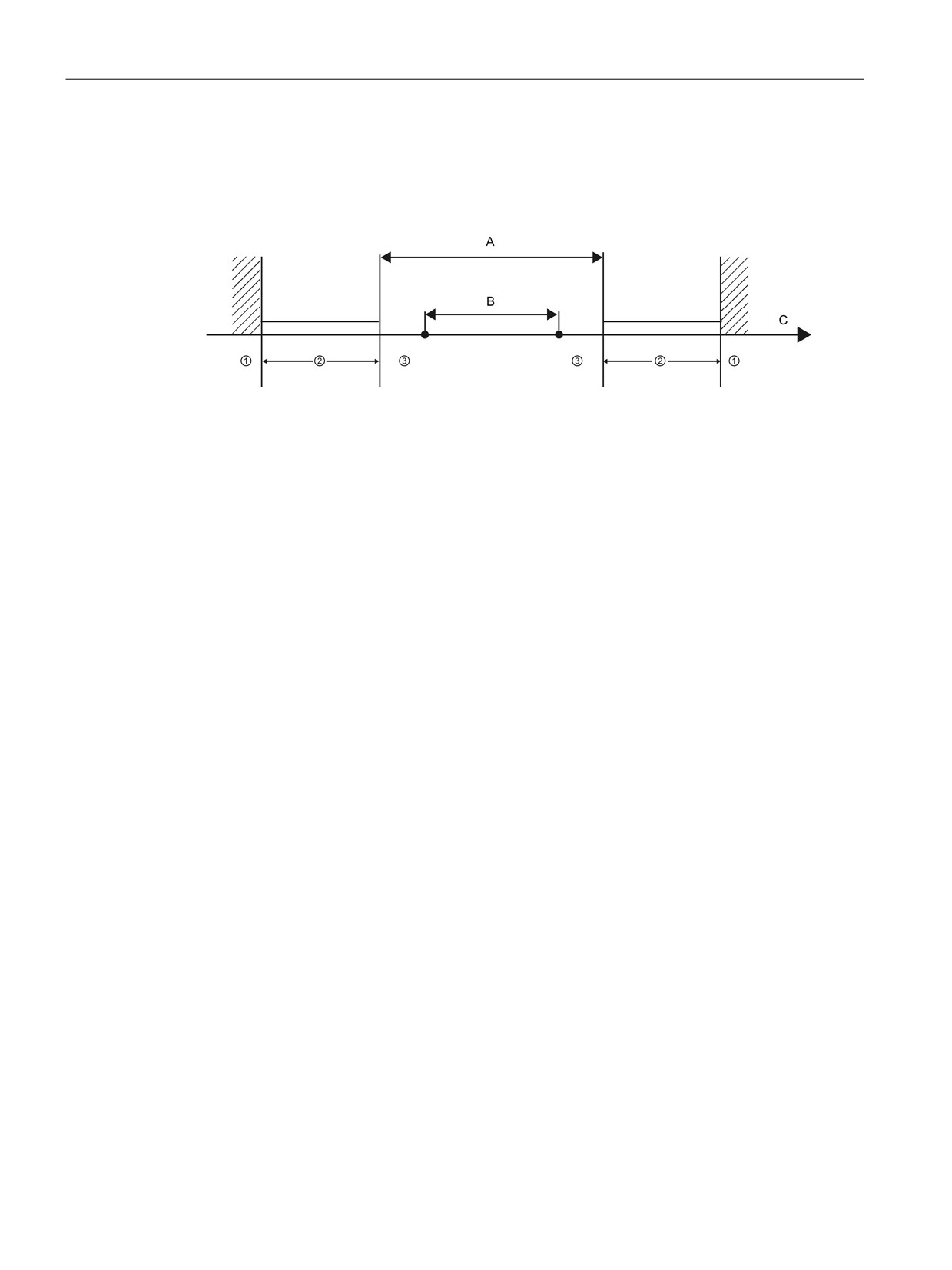
Motion control is easy
10.6 Operation of motion control for S7-1200
10.6.2
Hardware and software limit switches for motion control
Use the hardware and software limit switches to limit the "allowed travel range" and the
"working range" of your axis.
① Mechanical stop
A Allowed travel range for the axis
② Lower and upper hardware limits
B Working range of the axis
③ Lower and upper software limits
C Distance
Hardware and software limit switches must be activated prior to use in the configuration or in
the user program. Software limit switches are only active after homing the axis.
298
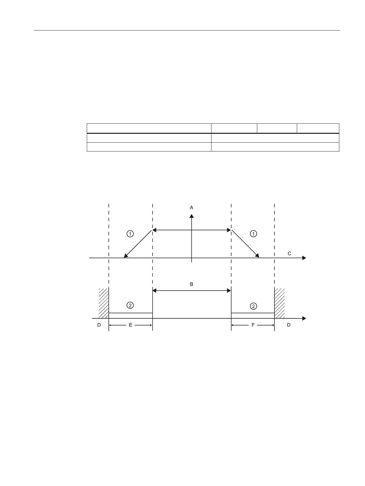
Motion control is easy
10.6 Operation of motion control for S7-1200
Hardware limit switches
Hardware limit switches determine the maximum travel range of the axis. Hardware limit
switches are physical switching elements that must be connected to interrupt-capable inputs
of the CPU. Use only hardware limit switches that remain permanently switched after being
approached. This switching status may only be revoked after a return to the allowed travel
range.
Table 10- 23 Available inputs for hardware limits
Description
RPS
LIM-
LIM+
Built-in I/O
I0.0 - I1.5
SB I/O
I4.0 - I4.3
When the hardware limit switches are approached, the axis brakes to a standstill at the
configured emergency deceleration. The specified emergency deceleration must be
sufficient to reliably stop the axis before the mechanical stop. The following diagram
presents the behavior of the axis after it approaches the hardware limit switches.
① The axis brakes to a standstill at the configured emergency deceleration.
② Range in which the hardware limit switches signal the stats "approached".
A
[Velocity]
B
Allowed travel range
C Distance
D Mechanical stop
E
Lower hardware limit switch
F
Upper hardware limit switch
299
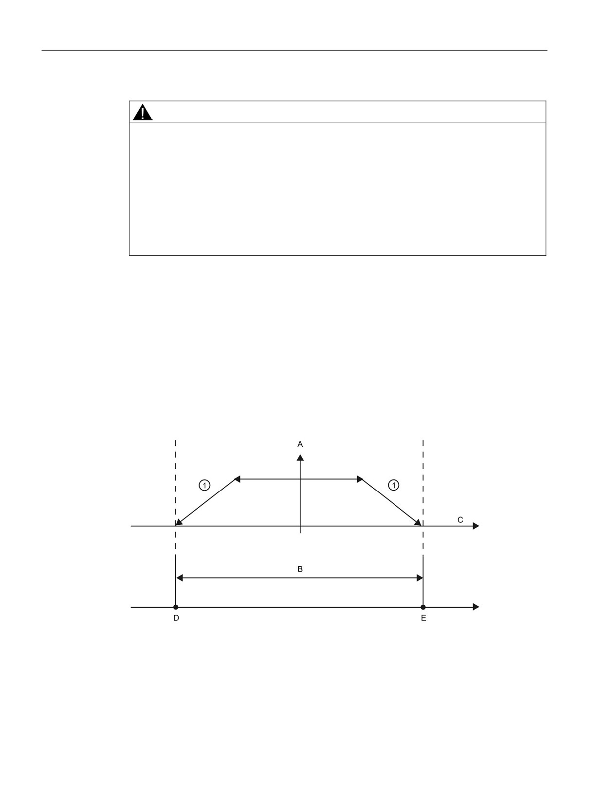
Motion control is easy
10.6 Operation of motion control for S7-1200
WARNING
Risks with changes to filter time for digital input channel
If the filter time for a digital input channel is changed from a previous setting, a new "0"
level input value may need to be presented for up to 20.0 ms accumulated duration before
the filter becomes fully responsive to new inputs. During this time, short "0" pulse events of
duration less than 20.0 ms may not be detected or counted.
This changing of filter times can result in unexpected machine or process operation, which
may cause death or serious injury to personnel, and/or damage to equipment.
To ensure that a new filter time goes immediately into effect, a power cycle of the CPU
must be applied.
Software limit switches
Software limit switches limit the "working range" of the axis. They should fall inside the
hardware limit switches relative to the travel range. Because the positions of the software
limit switches can be set flexibly, the working range of the axis can be restricted on an
individual basis depending on the current traversing profile. In contrast to hardware limit
switches, software limit switches are implemented exclusively by means of the software and
do not require their own switching elements.
If software limit switches are activated, an active motion is stopped at the position of the
software limit switch. The axis is braked at the configured deceleration. The following
diagram presents the behavior of the axis until it reaches the software limit switches.
① The axis brakes to a standstill at the configured deceleration.
A
[Velocity]
B
Working range
C Distance
D Lower software limit switch
E
Upper software limit switch
300
Motion control is easy
10.6 Operation of motion control for S7-1200
Use additional hardware limit switches if a mechanical endstop is located after the software
limit switches and there is a risk of mechanical damage.
Additional information
Your user program can override the hardware or software position limits by enabling or
disabling both hardware and software limits functionality. The selection is made from the
Axis DB.
● To enable or disable the hardware limit functionality, access the "Active" tag (Bool) in the
DB path "<axis name>/Config/PositonLimits_HW". The state of the "Active" tag enables
or disables the use of hardware position limits.
● To enable or disable software position limit functionality, access "Active" tag (Bool) in the
DB path "<axis name>/Config/Position Limits_SW". The state of this "Active" tag enables
or disables the software position limits.
You can also modify the software position limits with your user program (for example, to add
flexibility for machine setup or to shorten machine change-over time). Your user program can
write new values to the " MinPosition " and " MaxPosition " tags (engineering units in Real
format) in the DB "<axis name>/Config/PositionLimits_SW".
301
Motion control is easy
10.6 Operation of motion control for S7-1200
10.6.3
Homing
10.6.3.1
Homing the axis
Homing refers to the matching of the axis coordinates to the real, physical drive position. (If
the drive is currently at position x, the axis will be adjusted to be in position x.) For position-
controlled axes, the entries and displays for the position refer exactly to these axis
coordinates.
Note
The agreement between the axis coordinates and the real situation is extremely important.
This step is necessary to ensure that the absolute target position of the axis is also achieved
exactly with the drive.
The MC_Home instruction initiates the homing of the axis.
There are 4 different homing functions. The first two functions allow the user to set the
current position of the axis and the second two position the axis with respect to a Home
reference Sensor.
●
Mode 0 - Direct Referencing Absolute: When executed this mode tells the axis exactly
where it is. It sets the internal position variable to the value of the Position input of the
Homing instruction. This is used for machine calibration and setup.
The axis position is set regardless of the reference point switch. Active traversing motions
are not aborted. The value of the Position input parameter of the MC_Home instruction is
set immediately as the reference point of the axis. To assign the reference point to an
exact mechanical position, the axis must be at a standstill at this position at the time of
the homing operation.
●
Mode 1 - Direct Referencing Relative: When executed this mode uses the internal
position variable and adds the value of the Position input on the Homing instruction to it.
This is typically used to account for machine offset.
The axis position is set regardless of the reference point switch. Active traversing motions
are not aborted. The following statement applies to the axis position after homing: New
axis position = current axis position + value of the Position parameter of the MC_Home
instruction.
●
Mode 2 - Passive Referencing: When the axis is moving and passes the Reference Point
Switch the current position is set as the home position. This feature will help account for
normal machine wear and gear backlash and prevent the need for manual compensation
for wear. The Position input on the Homing instruction, as before, adds to the location
indicated by the Reference Point Switch allowing easy offset of the Home position.
During passive homing, the MC_Home instruction does not carry out any homing motion.
The traversing motion required for this step must be implemented by the user via other
motion control instructions. When the reference point switch is detected, the axis is
homed according to the configuration. Active traversing motions are not aborted upon
start of passive homing.
302