Siemens simatic S7-1200. Manual (2015) - page 3
Programming made easy
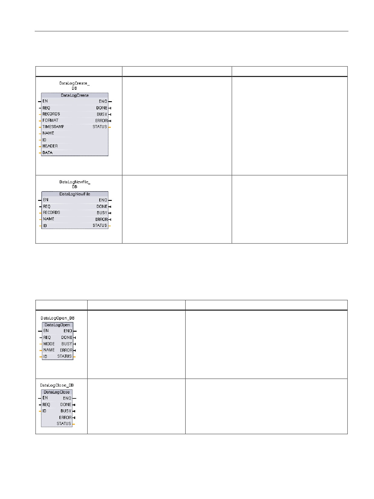
6.4 Easy to create data logs
Table 6- 22
DataLogCreate and DataLogNewFile instructions
LAD/FBD
SCL
Description
"DataLogCreate_DB"(
DataLogCreate1 creates and initializes a
req:=FALSE,
data log file stored in the \DataLogs directo-
records:=1,
ry of the CPU. The data log file is created
format:=1,
with a pre-determined fixed size.
timestamp:=1,
done=>_bool_out_,
busy=>_bool_out_,
error=>_bool_out_,
status=>_word_out_,
name:=_variant_in_,
ID:=_dword_inout_,
header:=_variant_inout_,
data:=_variant_inout_);
"DataLogNewFile_DB"(
DataLogNewFile1 allows your program to
req:=FALSE,
create a new data log file based upon an
records:=1,
existing data log file. A new data log will be
done=>_bool_out_,
created and implicitly opened based with
the specified NAME. The header record will
busy=>_bool_out_,
be duplicated from the original data log
error=>_bool_out_,
along with the original data log properties.
status=>_word_out_,
The original data log file will be implicitly
name=:_variant_in_,
closed.
ID:=_dword_inout_);
1
The DataLogCreate and DataLogNewFile operations extend over many program scan cycles. The actual time required
for the log file creation depends on the record structure and number of records. Before the new data log can be used for
other data log operations, your program logic must monitor the transition of the DONE bit to TRUE.
Table 6- 23 DataLogOpen and DataLogClose instructions
LAD/FBD
SCL
Description
"DataLogOpen_DB"(
The DataLogOpen instruction opens a pre-existing data log
req:=FALSE,
file. A data log must be opened before you can write new rec-
mode:=0,
ords to the log. Data logs can be opened and closed individu-
name:=_variant_in_,
ally. Eight data logs can be open at the same time.
done=>_bool_out_,
busy=>_bool_out_,
error=>_bool_out_,
status=>_word_out_,
ID:=_dword_inout_);
"DataLogClose_DB"(
The DataLogClose instruction closes an open data log file.
req:=FALSE,
DataLogWrite operations to a closed data log result in an error.
done=>_bool_out_,
No write operations are allowed to this data log until another
busy=>_bool_out_,
DataLogOpen operation is performed.
error=>_bool_out_,
A transition to STOP mode closes all open data log files.
status=>_word_out_,
ID:=_dword_inout_);
123
Programming made easy
6.5 Easy to monitor and test your user program
6.5
Easy to monitor and test your user program
6.5.1
Watch tables and force tables
You use "watch tables" for monitoring and modifying the values of a user program being
executed by the online CPU. You can create and save different watch tables in your project
to support a variety of test environments. This allows you to reproduce tests during
commissioning or for service and maintenance purposes.
With a watch table, you can monitor and interact with the CPU as it executes the user
program. You can display or change values not only for the tags of the code blocks and data
blocks, but also for the memory areas of the CPU, including the inputs and outputs (I and Q),
peripheral inputs (I:P), bit memory (M), and data blocks (DB).
With the watch table, you can enable the physical outputs (Q:P) of a CPU in STOP mode.
For example, you can assign specific values to the outputs when testing the wiring for the
CPU.
STEP 7 also provides a force table for "forcing" a tag to a specific value. For more
information about forcing, see the section on forcing values in the CPU (Page 340) in the
"Online and Diagnostics" chapter.
Note
The force values are stored in the CPU and not in the watch table.
You cannot force an input (or "I" address). However, you can force a peripheral input. To
force a peripheral input, append a ":P" to the address (for example: "On:P").
STEP 7 also provides the capability of tracing and recording program variables based on
trigger conditions (Page 353).
124

Programming made easy
6.5 Easy to monitor and test your user program
6.5.2
Cross reference to show usage
The Inspector window displays cross-reference information about how a selected object is
used throughout the complete project, such as the user program, the CPU and any HMI
devices. The "Cross-reference" tab displays the instances where a selected object is being
used and the other objects using it. The Inspector window also includes blocks which are
only available online in the cross-references. To display the cross-references, select the
"Show cross-references" command. (In the Project view, find the cross references in the
"Tools" menu.)
Note
You do not have to close the editor to see the cross-reference information.
You can sort the entries in the cross-reference. The cross-reference list provides an
overview of the use of memory addresses and tags within the user program.
● When creating and changing a program, you retain an overview of the operands, tags
and block calls you have used.
● From the cross-references, you can jump directly to the point of use of operands and
tags.
● During a program test or when troubleshooting, you are notified about which memory
location is being processed by which command in which block, which tag is being used in
which screen, and which block is called by which other block.
Table 6- 24 Elements of the cross reference
Column
Description
Object
Name of the object that uses the lower-level objects or that is being used by the
lower-level objects
Number
Number of uses
Point of use
Each location of use, for example, network
Property
Special properties of referenced objects, for example, the tag names in multi-
instance declarations
as
Shows additional information about the object, such as whether an instance DB is
used as template or as a multiple instance
Access
Type of access, whether access to the operand is read access (R) and/or write
access (W)
Address
Address of the operand
Type
Information on the type and language used to create the object
Path
Path of object in project tree
Depending on the installed products, the cross-reference table displays additional or different
columns.
125
Programming made easy
6.5 Easy to monitor and test your user program
6.5.3
Call structure to examine the calling hierarchy
The call structure describes the call hierarchy of the block within your user program. It
provides an overview of the blocks used, calls to other blocks, the relationships between
blocks, the data requirements for each block, and the status of the blocks. You can open the
program editor and edit blocks from the call structure.
Displaying the call structure provides you with a list of the blocks used in the user program.
STEP 7 highlights the first level of the call structure and displays any blocks that are not
called by any other block in the program. The first level of the call structure displays the OBs
and any FCs, FBs, and DBs that are not called by an OB. If a code block calls another block,
the called block is shown as an indentation under the calling block. The call structure only
displays those blocks that are called by a code block.
You can selectively display only the blocks causing conflicts within the call structure. The
following conditions cause conflicts:
● Blocks that execute any calls with older or newer code time stamps
● Blocks that call a block with modified interface
● Blocks that use a tag with modified address and/or data type
● Blocks that are called neither directly nor indirectly by an OB
● Blocks that call a non-existent or missing block
You can group several block calls and data blocks as a group. You use a drop-down list to
see the links to the various call locations.
You can also perform a consistency check to show time stamp conflicts. Changing the time
stamp of a block during or after the program is generated can lead to time stamp conflicts,
which in turn cause inconsistencies among the blocks that are calling and being called.
● Most time stamp and interface conflicts can be corrected by recompiling the code blocks.
● If compilation fails to clear up inconsistencies, use the link in the "Details" column to go to
the source of the problem in the program editor. You can then manually eliminate any
inconsistencies.
● Any blocks marked in red must be recompiled.
126
Programming made easy
6.5 Easy to monitor and test your user program
6.5.4
Diagnostic instructions to monitor the hardware
6.5.4.1
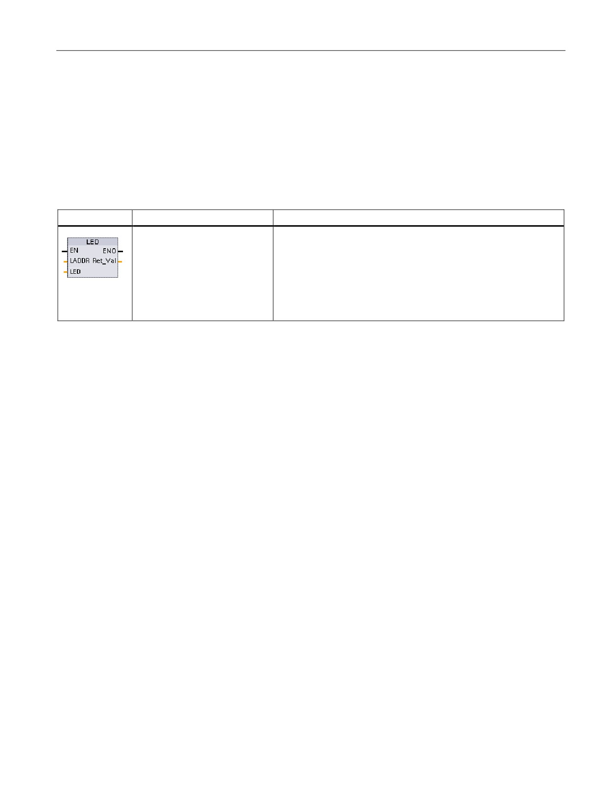
Reading the states of the LEDs on the CPU
The LED instruction allows your user program to determine the state of the LEDs on the
CPU. You can use this information for programming a tag for your HMI device.
Table 6- 25 LED instruction
LAD / FBD
SCL
Description
ret_val := LED(
RET_VAL returns the following LED states for the CPU
laddr:=_word_in_,
• RUN/STOP: green or yellow
LED:=_uint_in_);
• Error: red
• MAINT (maintenance): yellow
• Link: green
• Tx/Rx (transmit/receive): yellow
127
Programming made easy
6.5 Easy to monitor and test your user program
6.5.4.2
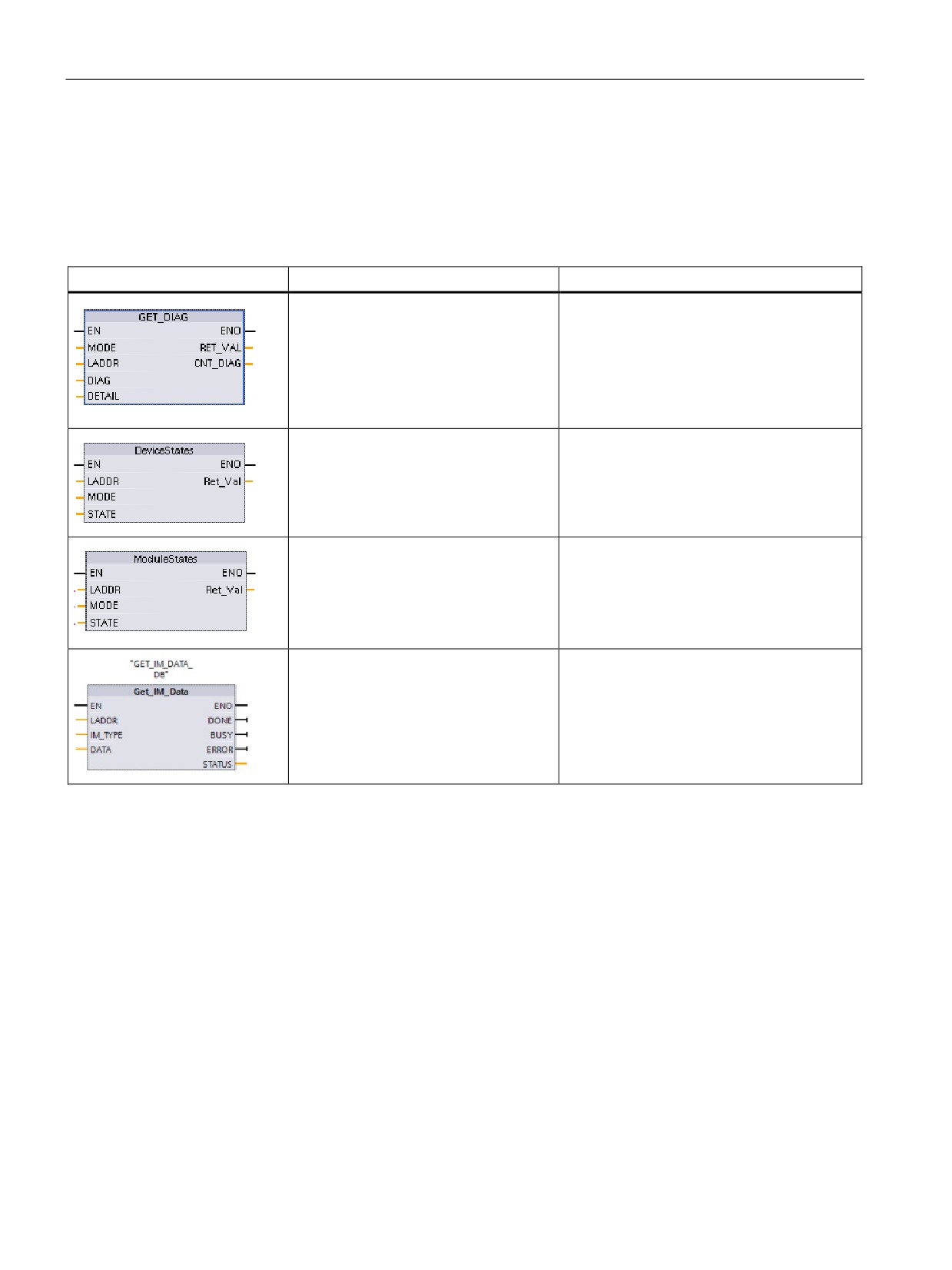
Instructions for reading the diagnostic status of the devices
STEP 7 also includes instructions for reading the status information that is provided by the
hardware devices on your network.
Table 6- 26
Diagnostic instructions
LAD / FBD
SCL
Description
ret_val := GET_DIAG(
The GET_DIAG instruction reads the diag-
mode:=_uint_in_,
nostic information from a specified hardware
laddr:=_word_in_,
device.
cnt_diag=>_uint_out_,
diag:=_variant_inout_,
de-
tail:=_variant_inout_);
ret_val := DeviceStates(
The DeviceStates instruction reads the status
laddr:=_word_in_,
of PROFINET or PROFIBUS devices.
mode:=_uint_in_,
state:=_variant_inout_);
ret_val := ModuleStates(
The ModuleStates instruction reads the sta-
laddr:=_word_in_,
tus of PROFINET or PROFIBUS modules.
mode:=_uint_in,
state:=_variant_inout);
"GET_IM_DATA_DB"(LADDR:=16#0,
Use the Get_IM_Data instruction to check the
IM_TYPE:=0,
identification and maintenance (I&M) data for
DONE=>_bool_out_,
the specified module or sub-module.
BUSY=>_bool_out_,
ERROR=>_bool_out_,
STATUS=>_word_out_,
DATA:=_variant_inout_);
128
Programming made easy
6.6 High-speed counter (HSC)
6.6
High-speed counter (HSC)
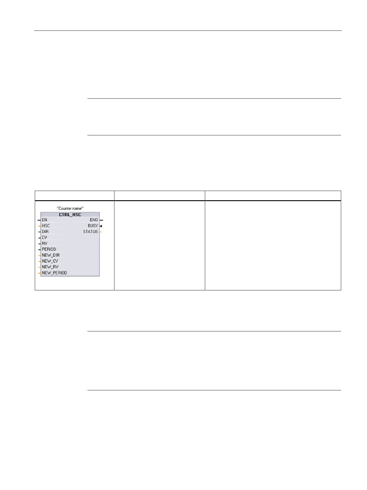
Use the high-speed counters (HSC) for counting events that occur faster than the OB
execution rate. The Counting instructions are in the Technology section of the instruction
tree. The CTRL_HSC instruction controls the operation of the HSC.
Note
If the events to be counted occur within the execution rate of the OB, use CTU, CTD, or
CTUD counter instructions. If the events occur faster than the OB execution rate, then use
the HSC.
You configure the parameters for each HSC in the device configuration for the CPU:
counting mode, I/O connections, interrupt assignment, and operation as a high-speed
counter or as a device to measure pulse frequency or period.
Table 6- 27
CTRL_HSC instruction
LAD / FBD
SCL
Description
"counter_name"(
Each CTRL_HSC instruction uses a structure stored
HSC:=W#16#0,
in a data block to maintain counter data.
DIR:=FALSE,
For SCL, you must first create the DB for the individ-
CV:=FALSE,
ual counter instruction before you can reference it.
RV:=FALSE,
For LAD and FBD, STEP 7 automatically creates the
Period:=FALSE,
DB when you insert the instruction.
New_DIR:=0,
New_CV:=L#0,
New_RV:=L#0,
New_Period:=0,
Busy=>_bool_out_,
Status=>_word_out_);
The CTRL_HSC instruction is typically placed in a hardware interrupt OB that is executed
when the counter hardware interrupt event is triggered. For example, if a CV=RV event
triggers the counter interrupt, then a hardware interrupt OB code block executes the
CTRL_HSC instruction and can change the reference value by loading a NEW_RV value.
Note
The current count value is not available in the CTRL_HSC parameters. The process image
address that stores the current count value is assigned during the hardware configuration of
the high-speed counter. You may use program logic to directly read the count value. The
value returned to your program will be a correct count for the instant in which the counter
was read. The counter will continue to count high-speed events. Therefore, the actual count
value could change before your program completes a process using an old count value.
129
Programming made easy
6.6 High-speed counter (HSC)
Some of the parameters for the HSC can be modified by your user program to provide
program control of the counting process:
● Set the counting direction to a NEW_DIR value
● Set the current count value to a NEW_CV value
● Set the reference value to a NEW_RV value
● Set the period value (for frequency measurement mode) to a NEW_PERIOD value
If the following Boolean flag values are set to 1 when the CTRL_HSC instruction is executed,
the corresponding NEW_xxx value is loaded to the counter. Multiple requests (more than
one flag is set at the same time) are processed in a single execution of the CTRL_HSC
instruction. Setting the following Boolean flag values to 0 results in no change.
● Setting DIR = 1 loads a NEW_DIR value.
● Setting CV = 1 loads a NEW_CV value.
● Setting RV = 1 loads a NEW_RV value
● Setting PERIOD = 1 loads a NEW_PERIOD value.
CTRL_HSC_EXT instruction (Control high-speed counter (extended)) instruction
STEP 7 and the S7-1200 CPU also support an extended high-speed counter instruction,
CTRL_HSC_EXT. This instruction allows the program to precisely measure the period of the
input pulses of a designated HSC. Refer to the S7-1200 Programmable Controller System
Manual for details.
130
Programming made easy
6.6 High-speed counter (HSC)
6.6.1
Operation of the high-speed counter
High-speed counters (HSC) can count events that occur faster than the cyclic OB execution
rate. If the events to be counted occur slower than the execution rate of the OB, you can use
CTU, CTD, or CTUD standard counter instructions. If the events occur faster than the OB
execution rate, then use the faster HSC device. The CTRL_HSC instruction allows your
program to programmatically change some of the HSC parameters.
For example: You can use the HSC as an input for an incremental shaft encoder. The shaft
encoder provides a specified number of counts per revolution and a reset pulse that occurs
once per revolution. The clock(s) and the reset pulse from the shaft encoder provide the
inputs to the HSC.
The HSC is loaded with the first of several presets, and the outputs are activated for the time
period where the current count is less than the current preset. The HSC provides an interrupt
when the current count is equal to preset, when reset occurs, and also when there is a
direction change.
As each current-count-value-equals-preset-value interrupt event occurs, a new preset is
loaded and the next state for the outputs is set. When the reset interrupt event occurs, the
first preset and the first output states are set, and the cycle is repeated.
Since the interrupts occur at a much lower rate than the counting rate of the HSC, precise
control of high-speed operations can be implemented with relatively minor impact to the scan
cycle of the CPU. The method of interrupt attachment allows each load of a new preset to be
performed in a separate interrupt routine for easy state control. Alternatively, all interrupt
events can be processed in a single interrupt routine.
HSC input channel selection
Use the following table and ensure that the CPU and SB input channels that you connect
can support the maximum pulse rates in your process signals.
Note
CPU and SB input channels (V4 or later firmware) have configurable input filter times
Earlier firmware versions had fixed HSC input channels and fixed filter times that could not
be changed.
V4 or later versions allow you to assign input channels and filter times. The default input filter
setting of 6.4 ms may be too slow for your process signals. You must optimize the digital
input filter times for the HSC inputs for your HSC application.
131

Programming made easy
6.6 High-speed counter (HSC)
Table 6- 28 CPU input: maximum frequency
CPU
CPU Input channel
1 or 2 phase mode
A/B Quadrature phase
mode
1211C
Ia.0 to Ia.5
100 kHz
80 kHz
1212C
Ia.0 to Ia.5
100 kHz
80 kHz
Ia.6, Ia.7
30 kHz
20 kHz
1214C and 1215C
Ia.0 to Ia.5
100kHz
80kHz
Ia.6 to Ib.5
30 kHz
20 kHz
1217C
Ia.0 to Ia.5
100 kHz
80 kHz
Ia.6 to Ib.1
30 kHz
20 kHz
Ib.2 to Ib.5
1 MHz
1 MHz
(.2+, .2- to .5+, .5-)
Table 6- 29 SB signal board input: maximum frequency (optional board)
SB signal board
SB input channel
1 or 2 phase mode
A/B Quadrature phase
mode
SB 1221, 200 kHz
Ie.0 to Ie.3
200kHz
160 kHz
SB 1223, 200 kHz
Ie.0, Ie.1
200kHz
160 kHz
SB 1223
Ie.0, Ie.1
30 kHz
20 kHz
Selecting the functionality for the HSC
All HSCs function the same way for the same counter mode of operation. Counter mode,
direction control, and initial direction are assigned in the CPU device configuration for HSC
function properties.
There are four basic types of HSC:
● Single-phase counter with internal direction control
● Single-phase counter with external direction control
● Two-phase counter with 2 clock inputs
● A/B phase quadrature counter
132

Programming made easy
6.6 High-speed counter (HSC)
You can use each HSC type with or without a reset input. When you activate the reset input
(with some restrictions, see the following table), the current value is cleared and held clear
until you deactivate the reset input.
●
Frequency function: Some HSC modes allow the HSC to be configured (Type of
counting) to report the frequency instead of a current count of pulses. Three different
frequency measuring periods are available: 0.01, 0.1, or 1.0 seconds.
The frequency measuring period determines how often the HSC calculates and reports a
new frequency value. The reported frequency is an average value determined by the total
number of counts in the last measuring period. If the frequency is rapidly changing, the
reported value will be an intermediate between the highest and lowest frequency
occurring during the measuring period. The frequency is always reported in Hertz (pulses
per second) regardless of the frequency measuring period setting.
●
Counter modes and inputs: The following table shows the inputs used for the clock,
direction control, and reset functions associated with the HSC.
●
Period measurement function: Period measurement is provided over the configured
measurement interval (10ms, 100ms, or 1000ms). The HSC_Period SDT returns period
measurements and provides the period measurements as two values: ElapsedTime and
EdgeCount. HSC inputs ID1000 to ID1020 are not affected by period measurements:
- ElapsedTime is an unsigned double integer value in nanoseconds representing the
time from the first counting event to the last counting event in the measurement
interval. If the EdgeCount = 0, then the ElapsedTime is the time since the last
counting event in a prior interval. ElapsedTime has a range from 0 to 4,294,967,280
ns (0x0000 0000 to 0xFFFF FFF0). Overflow is indicated by the value 4,294,967,295
(0xFFFF FFFF). The values from 0xFFFF FFF1 to 0xFFFF FFFE are reserved.
- EdgeCount is an unsigned double integer value representing the number of counting
events in the measurement interval.
The same input cannot be used for two different functions, but any input not being used
by the present mode of its HSC can be used for another purpose. For example, if HSC1
is in a mode that uses two built-in inputs but does not use the third external reset input
(default assignment at I0.3), then I0.3 can be used for edge interrupts or for HSC 2.
Table 6- 30 Counting modes for HSC
Type
Input 1
Input 2
Input 3
Function
Single-phase counter with
Clock
-
-
Count or frequency
internal direction control
Reset
Count
Single-phase counter with
Clock
Direction
-
Count or frequency
external direction control
Reset
Count
Two-phase counter with 2
Clock up
Clock down
-
Count or frequency
clock inputs
Reset
Count
A/B-phase quadrature coun-
Phase A
Phase B
-
Count or frequency
ter
Reset1
Count
1
For an encoder: Phase Z, Home
133

Programming made easy
6.6 High-speed counter (HSC)
Input addresses for the HSC
When you configure the CPU, you have the option to enable and configure the "Hardware
inputs" for each HSC.
All HSC inputs must be connected to terminals on the CPU module or optional signal board
that plugs into the front of the CPU module.
Note
As shown in the following tables, the default assignments for the optional signals for the
different HSCs overlap. For example, the optional external reset for HSC 1 uses the same
input as one of the inputs for HSC 2. For
For V4 CPUs or later, you can reassign the HSC inputs during the CPU configuration. You
do not have to use the default input assignments.
Always ensure that you have configured your HSCs so that any one input is not being used
by two HSCs.
The following tables show the HSC input default assignments for the on-board I/O of CPUs
and an optional SB. (If the SB model selected has only 2 inputs, only 4.0 and 4.1 inputs are
available.)
HSC input table definitions
● Single-phase: C is Clock input, [d] is direction input (optional), and [R] is external reset
input (optional)
(Reset is available only for "Counting" mode.)
● Two-phase: CU is Clock Up input, CD is Clock Down input, and [R] is external reset
input.(optional)
(Reset is available only for "Counting" mode.)
● AB-phase quadrature: A is the Clock A input, B is the Clock B input, and [R] is external
reset input (optional). (Reset is available only for "Counting" mode.)
Table 6- 31 CPU 1211C: HSC default address assignments
HSC
CPU on-board input
Optional SB input (default
counter mode
(default 0.x)
4.x) 1
0
1
2
3
4
5
0
1
2
3
HSC 1
1-phase
C
[d]
[R]
C
[d]
[R]
2-phase
CU
CD
[R]
CU
CD
[R]
AB-phase
A
B
[R]
A
B
[R]
HSC 2
1-phase
[R]
C
[d]
[R]
C
[d]
2-phase
[R]
CU
CD
[R]
CU
CD
AB-phase
[R]
A
B
[R]
A
B
HSC 3
1-phase
C
[d]
C
[d]
R]
2-phase
AB-phase
HSC4
1-phase
C
[d]
C
[d]
R]
2-phase
CU
CD
134

Programming made easy
6.6 High-speed counter (HSC)
HSC
CPU on-board input
Optional SB input (default
counter mode
(default 0.x)
4.x) 1
0
1
2
3
4
5
0
1
2
3
AB-phase
A
B
HSC 5
1-phase
C
[d]
[R]
2-phase
CU
CD
[R]
AB-phase
A
B
[R]
HSC 6
1-phase
[R]
C
[d]
2-phase
[R]
CU
CD
AB-phase
[R]
A
B
1
An SB with only 2 digital inputs provides only the 4.0 and 4.1 inputs.
Table 6- 32 CPU 1212C: HSC default address assignments
HSC counter mode
CPU on-board input
Optional
(default 0.x)
SB input
(default 4.x) 1
0
1
2
3
4
5
6
7
0
1
2
3
HSC 1
1-phase
C
[d]
[R]
C
[d]
[R]
2-phase
CU
CD
[R]
CU
CD
[R]
AB-phase
A
B
[R]
A
B
[R]
HSC 2
1-phase
[R]
C
[d]
[R]
C
[d]
2-phase
[R]
CU
CD
[R]
CU
CD
AB-phase
[R]
A
B
[R]
A
B
HSC 3
1-phase
C
[d]
[R]
C
[d]
[R]
2-phase
CU
CD
[R]
AB-phase
A
B
[R]
HSC 4
1-phase
[R]
C
[d]
C
[d]
[R]
2-phase
[R]
CU
CD
AB-phase
[R]
A
B
HSC 5
1-phase
C
[d]
[R]
2-phase
CU
CD
[R]
AB-phase
A
B
[R]
HSC 6
1-phase
[R]
C
[d]
2-phase
[R]
CU
CD
AB-phase
[R]
A
B
1
An SB with only 2 digital inputs provides only the 4.0 and 4.1 inputs.
135

Programming made easy
6.6 High-speed counter (HSC)
Table 6- 33 CPU 1214C, CPU 1215C, and CPU1217C:
HSC default address assignments
(on-board inputs only, see next table for optional SB addresses)
HSC counter mode
Digital input byte 0
Digital input byte 1
(default: 0.x)
(default: 1.x)
0
1
2
3
4
5
6
7
0
1
2
3
4
5
HSC 1
1-phase
C
[d]
[R]
2-phase
CU
CD
[R]
AB-phase
A
B
[R]
HSC 2
1-phase
[R]
C
[d]
2-phase
[R]
CU
CD
AB-phase
[R]
A
B
HSC 3
1-phase
C
[d]
[R]
2-phase
CU
CD
[R]
AB-phase
A
B
[R]
HSC 4
1-phase
[R]
C
[d]
2-phase
[R]
CU
CD
AB-phase
[R]
A
B
HSC 5
1-phase
C
[d]
[R]
2-phase
CU
CD
[R]
AB-phase
A
B
[R]
HSC 6
1-phase
C
[d]
[R]
2-phase
CU
CD
[R]
AB-phase
A
B
[R]
Table 6- 34 Optional SB in CPUs in above table: HSC default address assignments
HSC
Optional SB inputs (default: 4.x) 1
0
1
2
3
HSC 1
1-phase
C
[d]
[R]
2-phase
CU
CD
[R]
AB-phase
A
B
[R]
HSC 2
1-phase
[R]
C
[d]
2-phase
[R]
CU
CD
AB-phase
[R]
A
B
HSC 5
1-phase
C
[d]
[R]
2-phase
CU
CD
[R]
AB-phase
A
B
[R]
HSC 6
1-phase
[R]
C
[d]
2-phase
[R]
CU
CD
AB-phase
[R]
A
B
1
An SB with only 2 digital inputs provides only the 4.0 and 4.1 inputs.
136
Programming made easy
6.6 High-speed counter (HSC)
Note
The digital I/O points used by high-speed counter devices are assigned during CPU device
configuration. When digital I/O point addresses are assigned to HSC devices, the values of
the assigned I/O point addresses cannot be modified by the force function in a watch table.
6.6.2
Configuration of the HSC
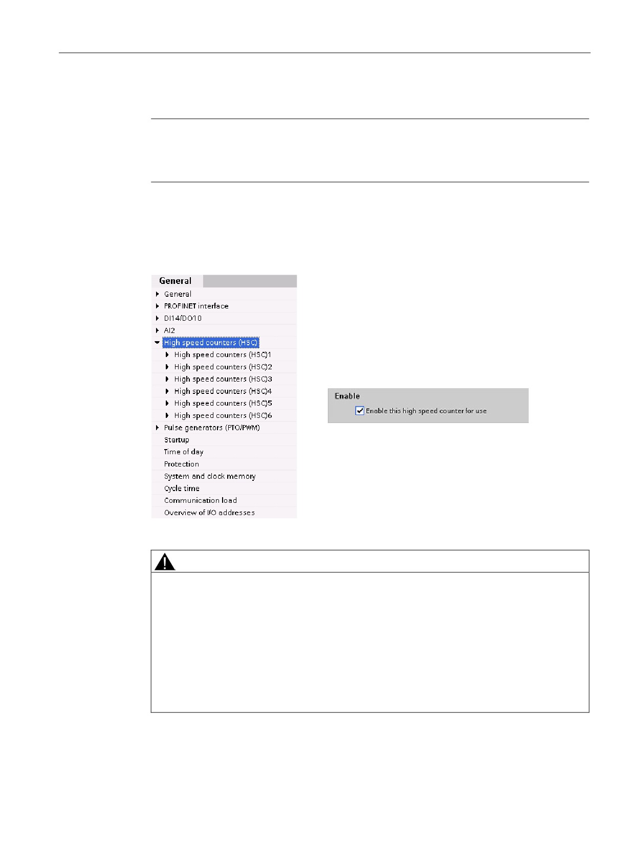
You may configure up to 6 high-speed counters. Edit
the CPU device configuration and assign the HSC
properties of each individual HSC.
Enable an HSC by selecting the "Enable" option for
that HSC
Use the CTRL_HSC and/or CTRL_HSC_EXT instruc-
tions in your user program to control the operation of
the HSC.
WARNING
Risks with changes to filter time setting for digital input channels
If the filter time for a digital input channel is changed from a previous setting, a new "0"
level input value might need to be presented for up to 20.0 ms accumulated duration before
the filter becomes fully responsive to new inputs. During this time, short "0" pulse events of
duration less than 20.0 ms may not be detected or counted.
This changing of filter times can result in unexpected machine or process operation, which
can cause death or serious injury to personnel, and/or damage to equipment.
To ensure that a new filter time goes immediately into effect, power cycle the CPU.
137
Programming made easy
6.6 High-speed counter (HSC)
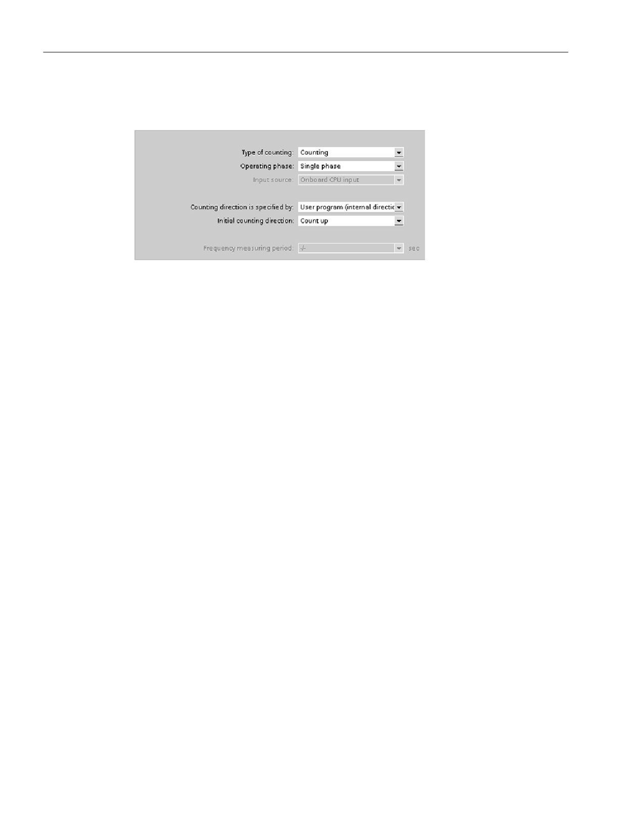
After enabling the HSC, configure the other parameters, such as counter function, initial
values, reset options and interrupt events.
For additional information about configuring the HSC, refer to the section on configuring the
CPU (Page 80).
138
Easy to communicate between devices
7
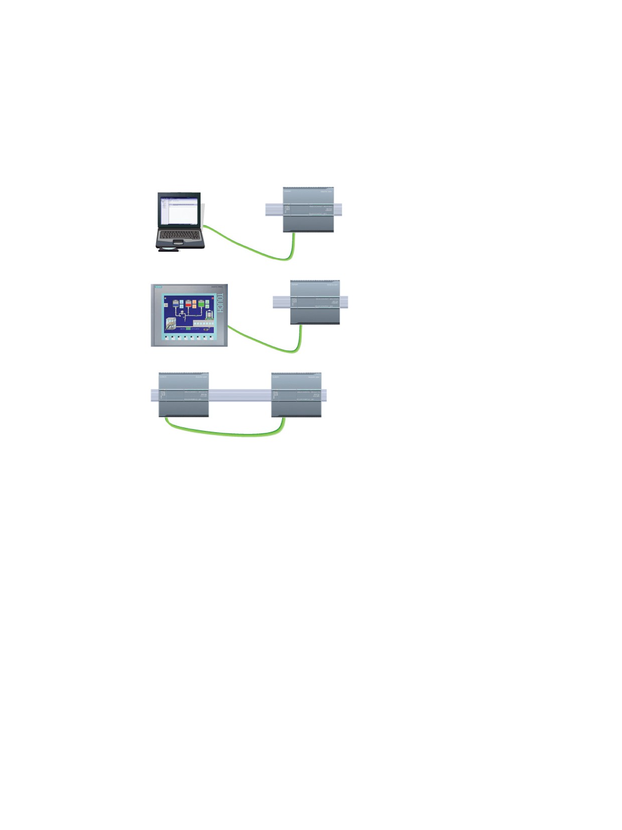
For a direct connection between the pro-
gramming device and a CPU:
• The project must include the CPU.
• The programming device is not part of the
project, but must be running STEP 7.
For a direct connection between an HMI
panel and a CPU, the project must include
both the CPU and the HMI.
For a direct connection between two CPUs:
• The project must include both CPUs.
• You must configure a network connection
between the two CPUs.
The S7-1200 CPU is a PROFINET IO controller and communicates with STEP 7 on a
programming device, with HMI devices, and with other CPUs or non-Siemens devices. An
Ethernet switch is not required for a direct connection between a programming device or HMI
and a CPU. An Ethernet switch is required for a network with more than two CPUs or HMI
devices.
By adding a PROFIBUS CM, your CPU can also function as either a master or a slave on a
PROFIBUS network.
Other communication interfaces (CM, CP or CB) support a variety of protocols, such as
Point-to-Point (PTP), Modbus, USS, GPRS (modem), security CP, and remote control CP.
139
Easy to communicate between devices
7.1 Creating a network connection
7.1
Creating a network connection
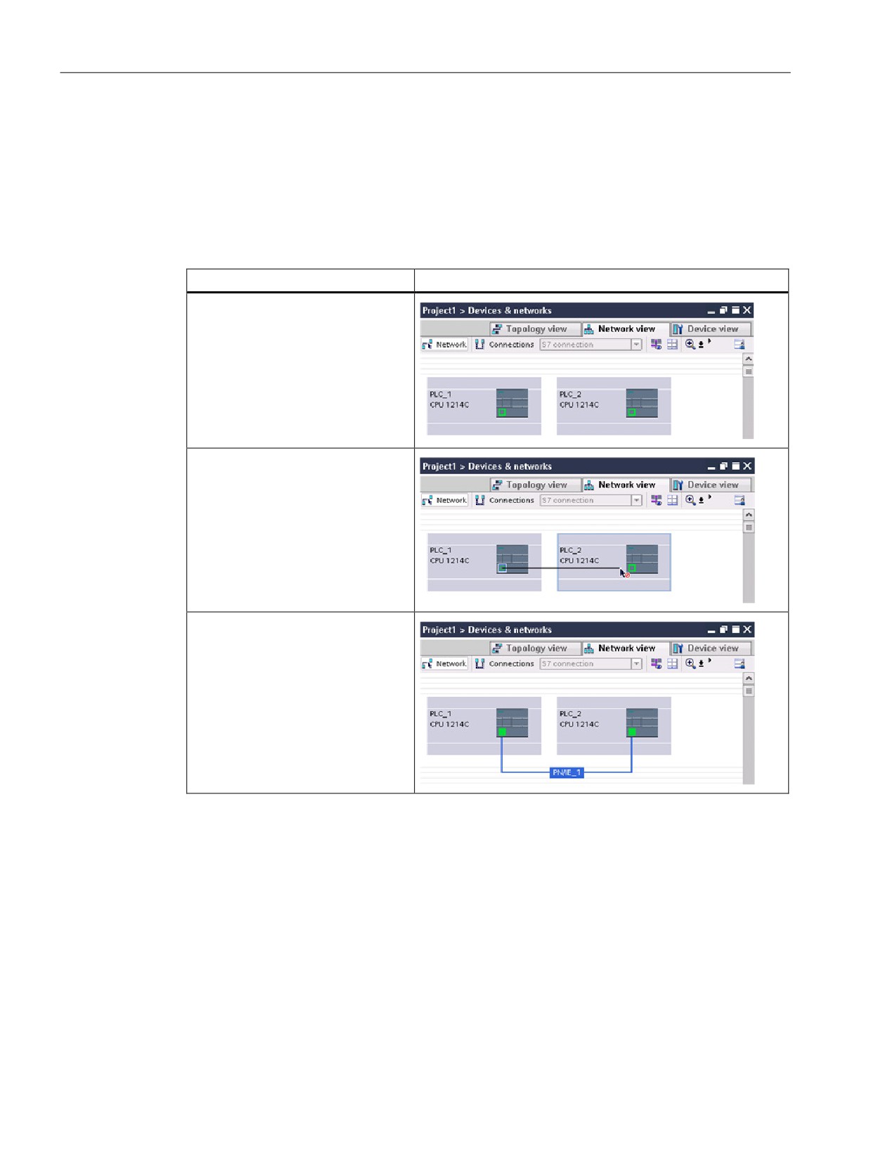
Use the "Network view" of Device configuration to create the network connections between
the devices in your project. After creating the network connection, use the "Properties" tab of
the inspector window to configure the parameters of the network.
Table 7- 1
Creating a network connection
Action
Result
Select "Network view" to display the
devices to be connected.
Select the port on one device and
drag the connection to the port on
the second device.
Release the mouse button to create
the network connection.
140

Easy to communicate between devices
7.2 Communication options
7.2
Communication options
The S7-1200 offers several types of communication between CPUs and programming
devices, HMIs, and other CPUs.
WARNING
If an attacker can physically access your networks, the attacker can possibly read and write
data.
The TIA Portal, the CPU, and HMIs (except HMIs using GET/PUT) use secure
communication that protects against replay and "man-in-the-middle" attacks. Once
communication is enabled, the exchange of signed messages takes place in clear text
which allows an attacker to read data, but protects against unauthorized writing of data.
The TIA Portal, not the communication process, encrypts the data of know-how protected
blocks.
All other forms of communication (I/O exchange through PROFIBUS, PROFINET, AS-i, or
other I/O bus, GET/PUT, T-Block, and communication modules (CM)) have no security
features. You must protect these forms of communication by limiting physical access. If an
attacker can physically access your networks utilizing these forms of communication, the
attacker can possibly read and write data.
For security information and recommendations, please see our "Operational Guidelines for
Industrial Security" (http://www.industry.siemens.com/topics/global/en/industrial-
security/Documents/operational_guidelines_industrial_security_en.pdf) on the Siemens
Service and Support site.
PROFINET
PROFINET is used for exchanging data through the user program with other
communications partners through Ethernet:
● In the S7-1200, PROFINET supports 16 IO devices with a maximum of 256 submodules,
and PROFIBUS allows 3 independent PROFIBUS DP Masters, supporting 32 slaves per
DP master, with a maximum of 512 modules per DP master.
● S7 communication
● User Datagram Protocol (UDP) protocol
● ISO on TCP (RFC 1006)
● Transport Control Protocol (TCP)
PROFINET IO controller
As an IO controller using PROFINET IO, the CPU communicates with up to 16 PN devices
on the local PN network or through a PN/PN coupler (link). Refer to PROFIBUS and
141
Easy to communicate between devices
7.2 Communication options
PROFIBUS
PROFIBUS is used for exchanging data through the user program with other
communications partners through the PROFIBUS network:
● With CM 1242-5, the CPU operates as a PROFIBUS DP slave.
● With CM 1243-5, the CPU operates as a PROFIBUS DP master class1.
● PROFIBUS DP Slaves, PROFIBUS DP Masters, and AS-i (the 3 left-side communication
modules) and PROFINET are separate communications networks that do not limit each
other.
AS-i
The S7-1200 CM 1243-2 AS-i Master allows the attachment of an AS-i network to an S7-
1200 CPU.
CPU-to-CPU S7 communication
You can create a communication connection to a partner station and use the GET and PUT
instructions to communicate with S7 CPUs.
TeleService communication
In TeleService via GPRS, an engineering station on which STEP 7 is installed communicates
via the GSM network and the Internet with a SIMATIC S7-1200 station with a CP 1242-7.
The connection runs via a telecontrol server that serves as an intermediary and is connected
to the Internet.
IO-Link
The S7-1200 SM 1278 4xIO-Link Master enables IO-Link devices to connect to an S7-1200
CPU.
142

Easy to communicate between devices
7.3 V4.1 asynchronous communication connections
7.3
V4.1 asynchronous communication connections
Overview of communication services
The CPU supports the following communication services:
Communication ser-
Functionality
Using PROFIBUS DP
Using
vice
Ethernet
CM 1243-5
CM 1242-5
DP master
DP slave
module
module
PG communication
Commissioning, testing, diagnos-
Yes
No
Yes
tics
HMI communication
Operator control and monitoring
Yes
No
Yes
S7 communication
Data exchange using configured
Yes
No
Yes
connections
Routing of PG func-
For example, testing and diagnos-
No
No
No
tions
tics beyond network boundaries
PROFIBUS DP
Data exchange between master
Yes
Yes
No
and slave
PROFINET IO
Data exchange between I/O con-
No
No
Yes
trollers and I/O devices
Web server
Diagnostics
No
No
Yes
SNMP
Standard protocol for network
No
No
Yes
(Simple Network Man-
diagnostics and parameterization
agement Protocol)
Open communication
Data exchange over Industrial
No
No
Yes
over TCP/IP
Ethernet with TCP/IP protocol (with
loadable FBs)
Open communication
Data exchange over Industrial
No
No
Yes
over ISO on TCP
Ethernet with ISO on TCP protocol
(with loadable FBs)
Open communication
Data exchange over Industrial
No
No
Yes
over UDP
Ethernet with UDP protocol (with
loadable FBs)
143
Easy to communicate between devices
7.3 V4.1 asynchronous communication connections
Available connections
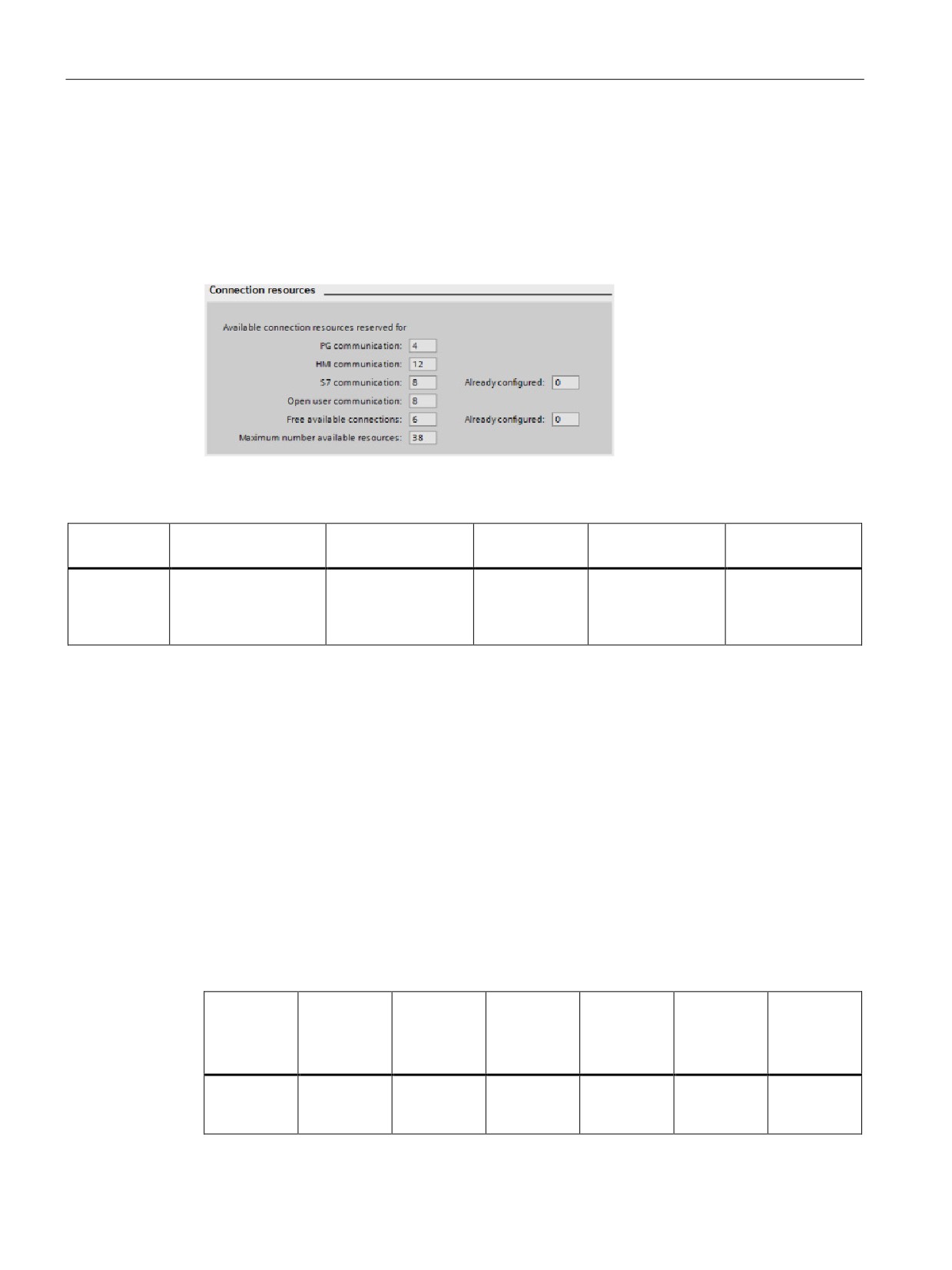
The CPU supports the following number of maximum simultaneous, asynchronous
communication connections for PROFINET and PROFIBUS. The maximum number of
connection resources allocated to each category are fixed; you cannot change these values.
However, you can configure the 6 "Free available connections" to increase the number of
any category as required by your application.
Based upon the allocated connection resources, the following number of connections per
device are available:
Programming
Human Machine
GET/PUT
Open User
Web browser
terminal (PG)
Interface (HMI)
client/server
Communications
Maximum
3
12
8
8
30
number of
(guaranteed to
(guaranteed to
(guaranteed to
connection
support
support
support
resources
1 PG device)
4 HMI devices)
3 web browsers)
For an example, a PG has 3 available connection resources. Depending on the current PG
functions in use, the PG might actually use 1, 2, or 3 of its available connection resources. In
the S7-1200, you are always guaranteed at least 1 PG; however, no more than 1 PG is
allowed.
Another example is the number of HMIs, as shown in the figure below. HMIs have 12
available connection resources. Depending on what HMI type or model that you have and
the HMI functions that you use, each HMI might actually use 1, 2, or 3 of its available
connection resources. Given the number of available connection resources being used, it
may be possible to use more than 4 HMIs at one time. However, you are always guaranteed
at least 4 HMIs. An HMI can use its available connection resources (1 each for a total of 3)
for the following functions:
● Reading
● Writing
● Alarming plus diagnostics
Example
HMI 1
HMI 2
HMI 3
HMI 4
HMI 5
Total con-
nection
resources
available
Connection
2
2
2
3
3
12
resources
used
144

Easy to communicate between devices
7.3 V4.1 asynchronous communication connections
Note
Web server (HTTP) connections: The CPU provides connections for multiple web browsers.
The number of browsers that the CPU can simultaneously support depends upon how many
connections a given web browser requests/utilizes.
Note
The Open User Communications, S7 connection, HMI, programming device, and Web server
(HTTP) communication connections may utilize multiple connection resources based upon
the features currently being used.
145
Easy to communicate between devices
7.4 PROFINET and PROFIBUS instructions
7.4
PROFINET and PROFIBUS instructions
PROFINET instructions
The TSEND_C and TRCV_C instructions make PROFINET communications simpler by
combining the functionality of the TCON and TDISCON instructions with the TSEND or
TRCV instruction.
● TSEND_C establishes a TCP or ISO on TCP communication connection to a partner
station, sends data, and can terminate the connection. After the connection is set up and
established, it is automatically maintained and monitored by the CPU. TSEND_C
combines the functions of the TCON, TDISCON and TSEND instructions into one
instruction.
● TRCV_C establishes a TCP or ISO-on-TCP communication connection to a partner CPU,
receives data, and can terminate the connection. After the connection is set up and
established, it is automatically maintained and monitored by the CPU. The TRCV_C
instruction combines the functions of the TCON, TDISCON, and TRCV instructions into
one instruction.
The TCON, TDISCON, TSEND and TRCV instructions are also supported.
Use the TUSEND and the TURCV instructions to transmit or receive data via UDP. TUSEND
and TURCV (as well as TSEND, TRCV, TCON, TDISCON) function asynchronously, which
means that the processing of the job extends over several instruction calls.
Use the IP_CONF instruction to change the IP configuration parameters from your user
program. IP_CONF works asynchronously. The execution extends over multiple calls.
PROFIBUS instructions
The DPNRM_DG (read diagnostics) instruction reads the current diagnostic data of a DP
slave in the format specified by EN 50 170 Volume 2, PROFIBUS.
Distributed I/O instructions for PROFINET, PROFIBUS and AS-i
You can use the following instructions with PROFINET, PROFIBUS, and GPRS.
● Use the RDREC (read record) and WRREC (write record) instructions to transfer a
specified data record between a component, such as a module in a central rack or a
distributed component (PROFIBUS DP or PROFINET IO).
● Use the RALRM (read alarm) instruction to read an interrupt and its information from a
DP slave or PROFINET IO device component. The information in the output parameters
contains the start information of the called OB as well as information of the interrupt
source.
● Use the DPRD_DAT (read consistent data) and DPWR_DAT (write consistent data)
instructions to transfer consistent data areas greater than 64 bytes from or to a DP
standard slave.
● For PROFIBUS only, use the DPNRM_DG instruction to read the current diagnostic data
of a DP slave in the format specified by EN 50 170 Volume 2, PROFIBUS.
146

Easy to communicate between devices
7.5 PROFINET
7.5
PROFINET
7.5.1
Open user communication
The integrated PROFINET port of the CPU supports multiple communications standards
over an Ethernet network:
● Transport Control Protocol (TCP)
● ISO on TCP (RFC 1006)
● User Datagram Protocol (UDP)
Table 7- 2
Protocols and communication instructions for each
Protocol
Usage examples
Entering data in the
Communication instruc-
Addressing type
receive area
tions
TCP
CPU-to-CPU com-
Ad hoc mode
Only TRCV_C and
Assigns port numbers to
munication
TRCV (V4.1 and legacy
the Local (active) and
instructions)
Partner (passive) devic-
Transport of frames
es
Data reception with
TSEND_C, TRCV_C,
specified length
TCON, TDISCON,
TSEND, and
TRCV(V4.1 and legacy
instructions)
ISO on TCP
CPU-to-CPU com-
Ad hoc mode
Only TRCV_C and
Assigns TSAPs to the
munication
TRCV (V4.1 and legacy
Local (active) and Part-
instructions)
ner (passive) devices
Message fragmenta-
tion and re-assembly
Protocol-controlled
TSEND_C, TRCV_C,
TCON, TDISCON,
TSEND, and TRCV
(V4.1 and legacy in-
structions)
UDP
CPU-to-CPU com-
User Datagram Protocol
TUSEND and TURCV
Assigns port numbers to
munication
the Local (active) and
Partner (passive) devic-
User program com-
es, but is not a dedicat-
munications
ed connection
S7 communication
CPU-to-CPU com-
Data transmission and
GET and PUT
Assigns TSAPs to the
munication
reception with specified
Local (active) and Part-
length
ner (passive) devices
Read/write data
from/to a CPU
PROFINET IO
CPU-to-PROFINET
Data transmission and
Built-in
Built-in
IO device communi-
reception with specified
cation
length
147

Easy to communicate between devices
7.5 PROFINET
7.5.1.1
Ad hoc mode
Typically, TCP and ISO-on-TCP receive data packets of a specified length, ranging from 1 to
8192 bytes. However, the TRCV_C and TRCV communication instructions also provide an
"ad hoc" communications mode that can receive data packets of a variable length from 1 to
1472 bytes.
Note
If you store the data in an "optimized" DB (symbolic only), you can receive data only in
arrays of Byte, Char, USInt, and SInt data types.
To configure the TRCV_C or TRCV instruction for ad hoc mode, set the ADHOC instruction
input parameter.
If you do not call the TRCV_C or TRCV instruction in ad hoc mode frequently, you could
receive more than one packet in one call. For example: If you were to receive five 100-byte
packets with one call, TCP would deliver these five packets as one 500-byte packet, while
ISO-on-TCP would restructure the packets into five 100-byte packets.
7.5.1.2
Connection IDs for the Open user communication instructions
When you insert the TSEND_C, TRCV_C or TCON PROFINET instructions into your user
program, STEP 7 creates an instance DB to configure the communications channel (or
connection) between the devices. Use the "Properties" (Page 152) of the instruction to
configure the parameters for the connection. Among the parameters is the connection ID for
that connection.
● The connection ID must be unique for the CPU. Each connection that you create must
have a different DB and connection ID.
● Both the local CPU and the partner CPU can use the same connection ID number for the
same connection, but the connection ID numbers are not required to match. The
connection ID number is relevant only for the PROFINET instructions within the user
program of the individual CPU.
● You can use any number for the connection ID of the CPU. However, configuring the
connection IDs sequentially from "1" provides an easy method for tracking the number of
connections in use for a specific CPU.
Note
Each TSEND_C, TRCV_C or TCON instruction in your user program creates a new
connection. It is important to use the correct connection ID for each connection.
148
Easy to communicate between devices
7.5 PROFINET
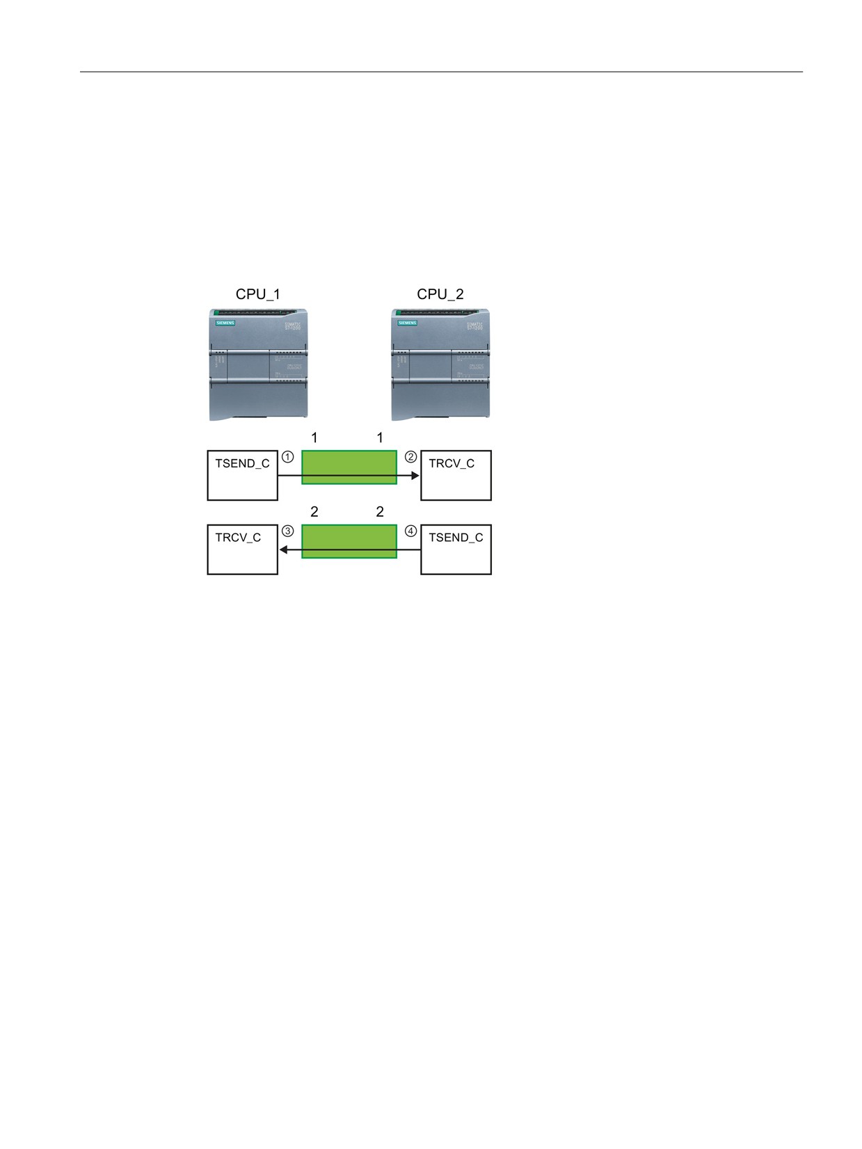
The following example shows the communication between two CPUs that utilize two
separate connections for sending and receiving the data.
● The TSEND_C instruction in CPU_1 links to the TRCV_C in CPU_2 over the first
connection ("connection ID 1" on both CPU_1 and CPU_2).
● The TRCV_C instruction in CPU_1 links to the TSEND_C in CPU_2 over the second
connection ("connection ID 2" on both CPU_1 and CPU_2).
① TSEND_C on CPU_1 creates a con-
nection and assigns a connection ID
to that connection (connection ID 1 for
CPU_1).
② TRCV_C on CPU_2 creates the con-
nection for CPU_2 and assigns the
connection ID (connection ID 1 for
CPU_2).
③ TRCV_C on CPU_1 creates a second
connection for CPU_1 and assigns a
different connection ID for that con-
nection (connection ID 2 for CPU_1).
④ TSEND_C on CPU_2 creates a sec-
ond connection and assigns a different
connection ID for that connection
(connection ID 2 for CPU_2).
149
Easy to communicate between devices
7.5 PROFINET
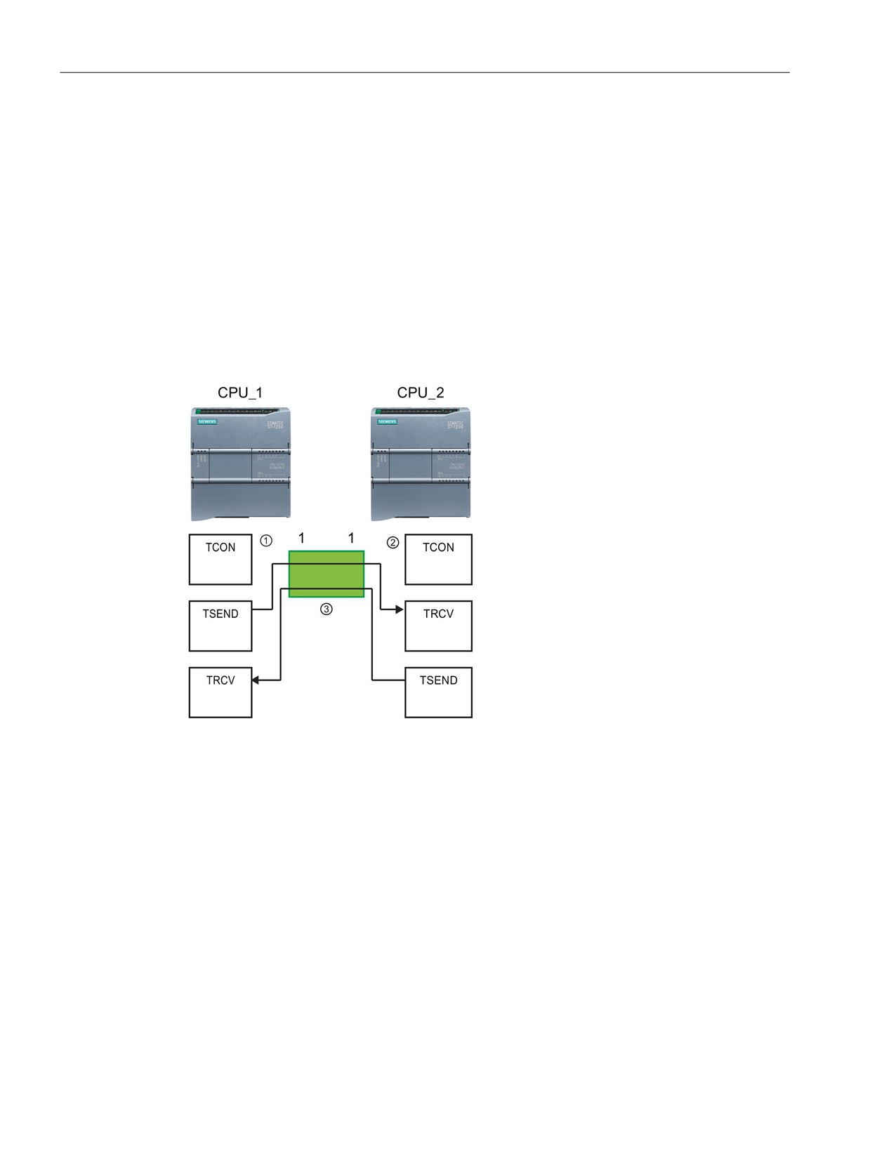
The following example shows the communication between two CPUs that utilize 1
connection for both sending and receiving the data.
●
Each CPU uses a TCON instruction to configure the connection between the two CPUs.
●
The TSEND instruction in CPU_1 links to the TRCV instruction in CPU_2 by using the
connection ID ("connection ID 1") that was configured by the TCON instruction in CPU_1.
The TRCV instruction in CPU_2 links to the TSEND instruction in CPU_1 by using the
connection ID ("connection ID 1") that was configured by the TCON instruction in CPU_2.
●
The TSEND instruction in CPU_2 links to the TRCV instruction in CPU_1 by using the
connection ID ("connection ID 1") that was configured by the TCON instruction in CPU_2.
The TRCV instruction in CPU_1 links to the TSEND instruction in CPU_2 by using the
connection ID ("connection ID 1") that was configured by the TCON instruction in CPU_1.
① TCON on CPU_1 creates a connec-
tion and assigns a connection ID for
that connection on CPU_1 (ID=1).
② TCON on CPU_2 creates a connec-
tion and assigns a connection ID for
that connection on CPU_2 (ID=1).
③ TSEND and TRCV on CPU_1 use the
connection ID created by the TCON
on CPU_1 (ID=1).
TSEND and TRCV on CPU_2 use the
connection ID created by the TCON
on CPU_2 (ID=1).
150
Easy to communicate between devices
7.5 PROFINET
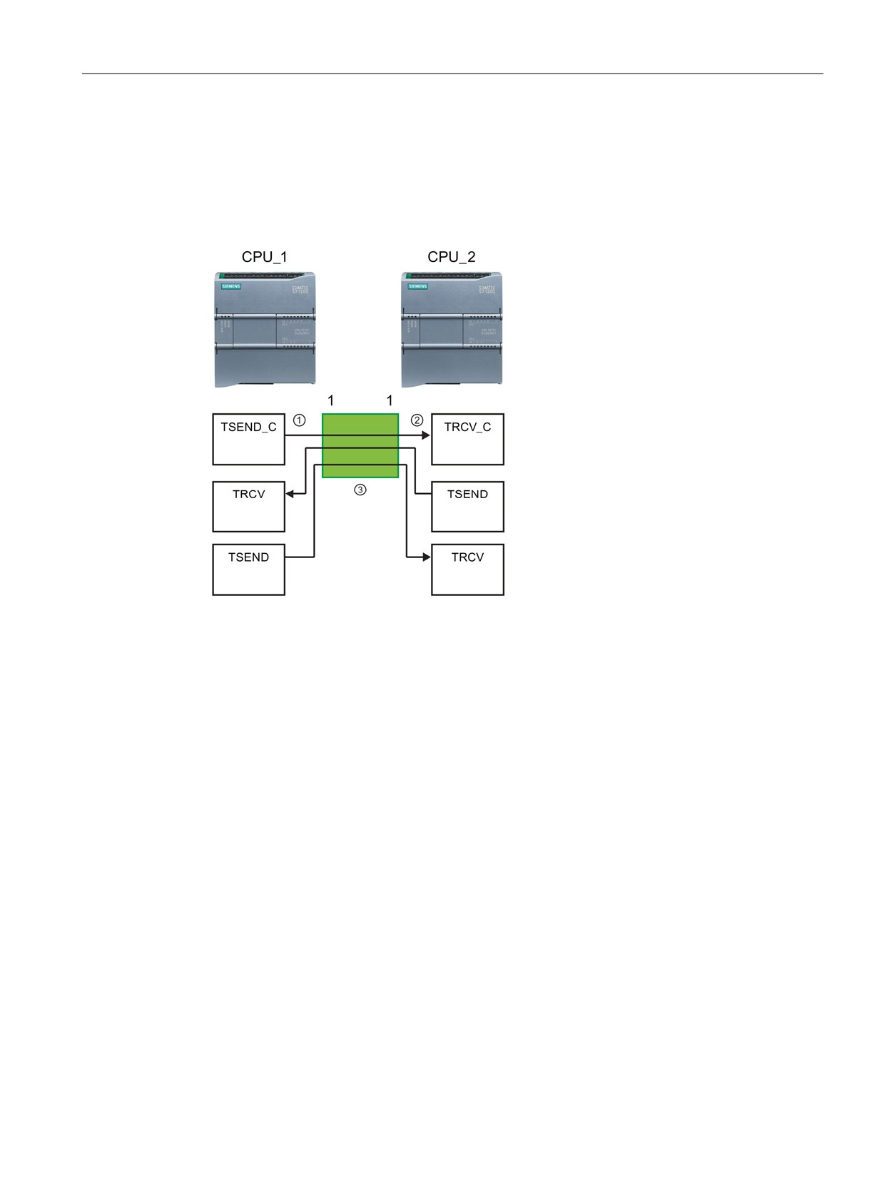
As shown in the following example, you can also use individual TSEND and TRCV
instruction to communication over a connection created by a TSEND_C or TRCV_C
instruction. The TSEND and TRCV instructions do not themselves create a new connection,
so must use the DB and connection ID that was created by a TSEND_C, TRCV_C or TCON
instruction.
① TSEND_C on CPU_1 creates a con-
nection and assigns a connection ID
to that connection (ID=1).
② TRCV_C on CPU_2 creates a connec-
tion and assigns the connection ID to
that connection on CPU_2 (ID=1).
③ TSEND and TRCV on CPU_1 use the
connection ID created by the
TSEND_C on CPU_1 (ID=1).
TSEND and TRCV on CPU_2 use the
connection ID created by the TRCV_C
on CPU_2 (ID=1).
151

Easy to communicate between devices
7.5 PROFINET
7.5.1.3
Parameters for the PROFINET connection
The TSEND_C, TRCV_C and TCON instructions require that connection-related parameters
be specified in order to connect to the partner device. These parameters are assigned by the
TCON_Param structure for the TCP, ISO-on-TCP, and UDP protocols. Typically, you use the
"Configuration" tab of the "Properties" of the instruction to specify these parameters. If the
"Configuration" tab is not accessible, then you must specify the TCON_Param structure
programmatically.
TCON_Param
Table 7- 3
Structure of the connection description (TCON_Param)
Byte
Parameter and data type
Description
0 … 1
block_length
UInt
Length: 64 bytes (fixed)
2 … 3
id
CONN_OUC
Reference to this connection: Range of values: 1 (default) to 4095.
(Word)
Specify the value of this parameter for the TSEND_C, TRCV_C or
TCON instruction under ID.
4
connection_type
USInt
Connection type:
•
17: TCP (default)
•
18: ISO-on-TCP
•
19: UDP
5
active_est
Bool
ID for the type of connection:
• TCP and ISO-on-TCP:
- FALSE: Passive connection
- TRUE: Active connection (default)
• UDP: FALSE
6
local_device_id
USInt
ID for the local PROFINET or Industrial Ethernet interface:
1 (default)
7
local_tsap_id_len
USInt
Length of parameter local_tsap_id used, in bytes; possible values:
• TCP: 0 (active, default) or 2 (passive)
• ISO-on-TCP: 2 to 16
• UDP: 2
8
rem_subnet_id_len
USInt
This parameter is not used.
9
rem_staddr_len
USInt
Length of address of partner end point, in bytes:
•
0: unspecified (parameter rem_staddr is irrelevant)
•
4 (default): Valid IP address in parameter rem_staddr (only for
TCP and ISO-on-TCP)
10
rem_tsap_id_len
USInt
Length of parameter rem_tsap_id used, in bytes; possible values:
• TCP: 0 (passive) or 2 (active, default)
• ISO-on-TCP: 2 to 16
• UDP: 0
11
next_staddr_len
USInt
This parameter is not used.
152

Easy to communicate between devices
7.5 PROFINET
Byte
Parameter and data type
Description
12 … 27
local_tsap_id
Array [1..16] of
Local address component of connection:
Byte
• TCP and ISO-on-TCP: local port no. (possible values: 1 to
49151; recommended values: 2000...5000):
- local_tsap_id[1] = high byte of port number in hexadecimal
notation;
- local_tsap_id[2] = low byte of port number in hexadecimal
notation;
- local_tsap_id[3-16] = irrelevant
• ISO-on-TCP: local TSAP-ID:
- local_tsap_id[1] = B#16#E0;
- local_tsap_id[2] = rack and slot of local end points (bits 0 to
4: slot number, bits 5 to 7: rack number);
- local_tsap_id[3-16] = TSAP extension, optional
• UDP: This parameter is not used.
Note: Make sure that every value of local_tsap_id is unique within
the CPU.
28 … 33
rem_subnet_id
Array [1..6] of
This parameter is not used.
USInt
34 … 39
rem_staddr
Array [1..6] of
TCP and ISO-on-TCP only: IP address of the partner end point.
USInt
(Not relevant for passive connections.) For example, IP address
192.168.002.003 is stored in the following elements of the array:
rem_staddr[1] = 192
rem_staddr[2] = 168
rem_staddr[3] = 002
rem_staddr[4] = 003
rem_staddr[5-6]= irrelevant
40 … 55
rem_tsap_id
Array [1..16] of
Partner address component of connection
Byte
• TCP: partner port number. Range: 1 to 49151; Recommended
values: 2000 to 5000):
- rem_tsap_id[1] = high byte of the port number in hexadeci-
mal notation
- rem_tsap_id[2] = low byte of the port number in hexadeci-
mal notation;
- rem_tsap_id[3-16] = irrelevant
• ISO-on-TCP: partner TSAP-ID:
- rem_tsap_id[1] = B#16#E0
- rem_tsap_id[2] = rack and slot of partner end point (bits 0
to 4: Slot number, bits 5 to 7: rack number)
- rem_tsap_id[3-16] = TSAP extension, optional
• UDP: This parameter is not used.
56 … 61
next_staddr
Array [1..6] of
This parameter is not used.
Byte
62 … 63
spare
Word
Reserved: W#16#0000
153
Easy to communicate between devices
7.5 PROFINET
7.5.2
Configuring the Local/Partner connection path
A Local / Partner (remote) connection defines a logical assignment of two communication
partners to establish communication services. A connection defines the following:
● Communication partners involved (One active, one passive)
● Type of connection (for example, a PLC, HMI, or device connection)
● Connection path
Communication partners execute the instructions to set up and establish the communication
connection. You use parameters to specify the active and passive communication end point
partners. After the connection is set up and established, it is automatically maintained and
monitored by the CPU.
If the connection is terminated (for example, due to a line break), the active partner attempts
to re-establish the configured connection. You do not have to execute the communication
instruction again.
Connection paths
After inserting a TSEND_C, TRCV_C or TCON instruction into the user program, the
inspector window displays the properties of the connection whenever you have selected any
part of the instruction. Specify the communication parameters in the "Configuration" tab of
the "Properties" for the communication instruction.
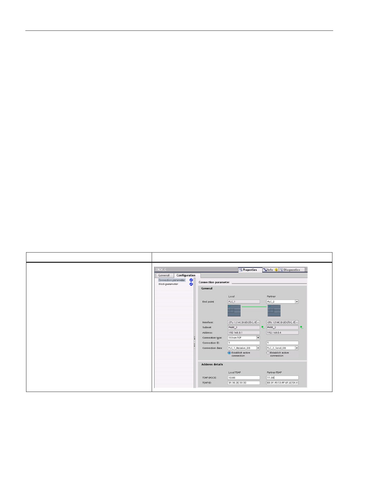
Table 7- 4
Configuring the connection path (using the properties of the instruction)
TCP, ISO-on-TCP, and UDP
Connection properties
For the TCP, ISO-on-TCP, and UDP Ethernet
protocols, use the "Properties" of the instruction
(TSEND_C, TRCV_C, or TCON) to configure the
"Local/Partner" connections.
The illustration shows the "Connection proper-
ties" of the "Configuration tab" for an ISO-on-
TCP connection.
154
Easy to communicate between devices
7.5 PROFINET
Note
When you configure the connection properties for one CPU, STEP 7 allows you either to
select a specific connection DB in the partner CPU (if one exists), or to create the connection
DB for the partner CPU. The partner CPU must already have been created for the project
and cannot be an "unspecified" CPU.
You must still insert a TSEND_C, TRCV_C or TCON instruction into the user program of the
partner CPU. When you insert the instruction, select the connection DB that was created by
the configuration.
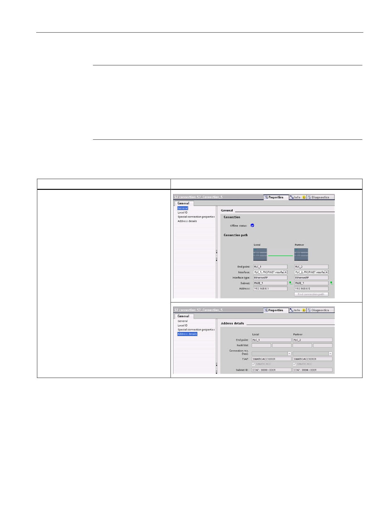
Table 7- 5
Configuring the connection path for S7 communication (Device configuration)
S7 communication (GET and PUT)
Connection properties
For S7 communication, use the "Devices & net-
works" editor of the network to configure the
Local/Partner connections. You can click the
"Highlighted: Connection" button to access the
"Properties".
The "General" tab provides several properties:
• "General" (shown)
• "Local ID"
• "Special connection properties"
• "Address details" (shown)
Refer to "Protocols" (Page 147) in the "PROFINET" section or to "Creating an S7
connection" (Page 169) in the "S7 communication" section for more information and a list of
available communication instructions.
155

Easy to communicate between devices
7.5 PROFINET
Table 7- 6
Parameters for the multiple CPU connection
Parameter
Definition
Address
Assigned IP addresses
General
End point
Name assigned to the partner (receiving) CPU
Interface
Name assigned to the interfaces
Subnet
Name assigned to the subnets
Interface type
S7 communication only: Type of interface
Connection type
Type of Ethernet protocol
Connection ID
ID number
Connection data
Local and Partner CPU data storage location
Establish active connec-
Radio button to select Local or Partner CPU as the active connection
tion
Address de-
End point
S7 communication only: Name assigned to the partner (receiving) CPU
tails
Rack/slot
S7 communication only: Rack and slot location
Connection resource
S7 communication only: Component of the TSAP used when configuring an
S7 connection with an S7-300 or S7-400 CPU
Port (decimal):
TCP and UPD: Partner CPU port in decimal format
TSAP 1 and Subnet ID:
ISO on TCP (RFC 1006) and S7 communication: Local and partner CPU
TSAPs in ASCII and hexadecimal formats
1
When configuring a connection with an S7-1200 CPU for ISO-on-TCP, use only ASCII characters in the TSAP extension
for the passive communication partners.
Transport Service Access Points (TSAPs)
Using TSAPs, ISO on TCP protocol and S7 communication allows multiple connections to a
single IP address (up to 64K connections). TSAPs uniquely identify these communication
end point connections to an IP address.
In the "Address Details" section of the Connection Parameters dialog, you define the TSAPs
to be used. The TSAP of a connection in the CPU is entered in the "Local TSAP" field. The
TSAP assigned for the connection in your partner CPU is entered under the "Partner TSAP"
field.
Port Numbers
With TCP and UDP protocols, the connection parameter configuration of the Local (active)
connection CPU must specify the remote IP address and port number of the Partner
(passive) connection CPU.
In the "Address Details" section of the Connection Parameters dialog, you define the ports to
be used. The port of a connection in the CPU is entered in the "Local Port" field. The port
assigned for the connection in your partner CPU is entered under the "Partner Port" field.
156
Easy to communicate between devices
7.6 PROFIBUS
7.6
PROFIBUS
A PROFIBUS system uses a bus master to poll slave devices distributed in a multi-drop
fashion on an RS485 serial bus. A PROFIBUS slave is any peripheral device (I/O
transducer, valve, motor drive, or other measuring device) which processes information and
sends its output to the master. The slave forms a passive station on the network since it
does not have bus access rights, and can only acknowledge received messages, or send
response messages to the master upon request. All PROFIBUS slaves have the same
priority, and all network communication originates from the master.
A PROFIBUS master forms an "active station" on the network. PROFIBUS DP defines two
classes of masters. A class 1 master (normally a central programmable controller (PLC) or a
PC running special software) handles the normal communication or exchange of data with
the slaves assigned to it. A class 2 master (usually a configuration device, such as a laptop
or programming console used for commissioning, maintenance, or diagnostics purposes) is
a special device primarily used for commissioning slaves and for diagnostic purposes.
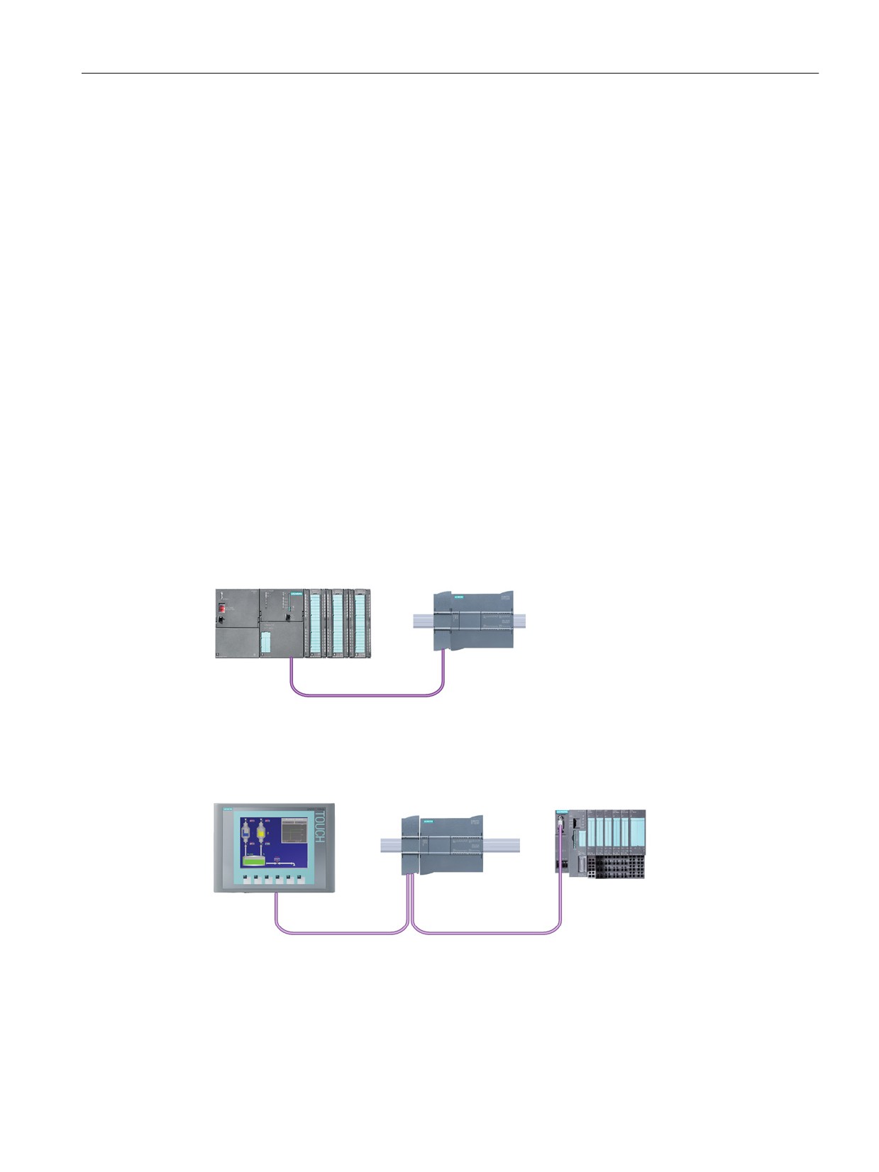
The S7-1200 is connected to a PROFIBUS network as a DP slave with the CM 1242-5
communication module. The CM 1242-5 (DP slave) module can be the communications
partner of DP V0/V1 masters. If you want to configure the module in a third-party system,
there is a GSD file available for the CM 1242-5 (DP slave) on the CD that ships with the
module and on Siemens Automation Customer Support
K72425DX300XE0&caller=view) pages on the Internet.
In the figure below, the S7-1200 is a DP slave to an S7-300 controller:
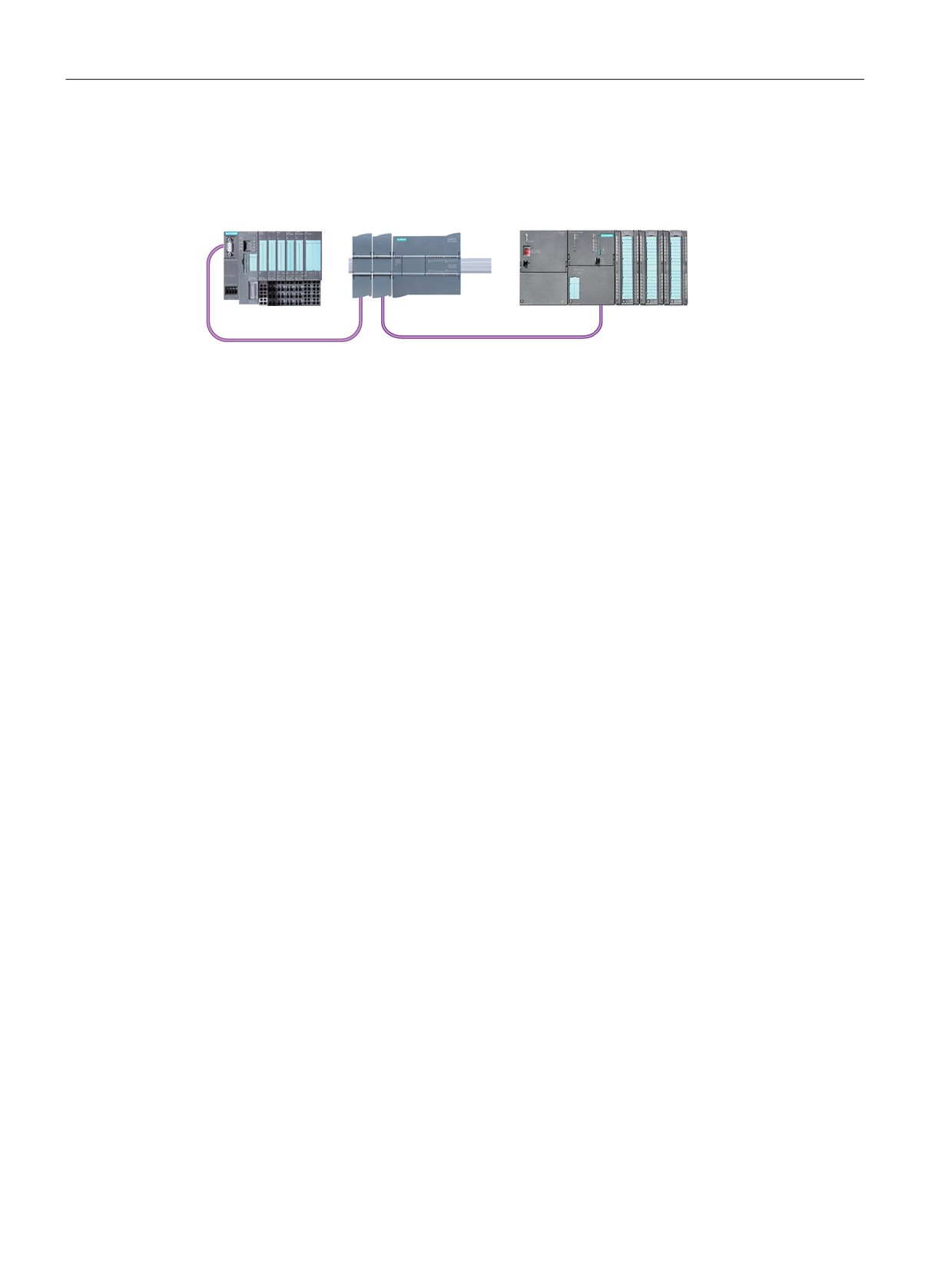
The S7-1200 is connected to a PROFIBUS network as a DP master with the CM 1243-5
communication module. The CM 1243-5 (DP master) module can be the communications
partner of DP V0/V1 slaves. In the figure below, the S7-1200 is a master controlling an
ET200S DP slave:
157
Easy to communicate between devices
7.6 PROFIBUS
If a CM 1242-5 and a CM 1243-5 are installed together, an S7-1200 can perform as both a
slave of a higher-level DP master system and a master of a lower-level DP slave system,
simultaneously:
For V4.0, you can configure a maximum of three PROFIBUS CMs per station, in which there
can be any combination of DP master or DP slave CMs. DP masters in a V3.0 or greater
CPU firmware implementation can each control a maximum of 32 slaves.
The configuration data of the PROFIBUS CMs is stored on the local CPU. This allows simple
replacement of these communications modules when necessary.
7.6.1
Communications services of the PROFIBUS CMs
The PROFIBUS CMs use the PROFIBUS DP-V1 protocol.
Types of communication with DP-V1
The following types of communication are available with DP-V1:
● Cyclic communication (CM 1242-5 and CM 1243-5)
Both PROFIBUS modules support cyclic communication for the transfer of process data
between DP slave and DP master.
Cyclic communication is handled by the operating system of the CPU. No software blocks
are required for this. The I/O data is read or written directly from/to the process image of
the CPU.
● Acyclic communication (CM 1243-5 only)
The DP master module also supports acyclic communication using software blocks:
- The "RALRM" instruction is available for interrupt handling.
- The "RDREC" and "WRREC" instructions are available for transferring configuration
and diagnostics data.
Functions not supported by the CM 1243-5: SYNC/FREEZE and Get_Master_Diag
158
Easy to communicate between devices
7.6 PROFIBUS
Other communications services of the CM 1243-5
The CM 1243-5 DP master module supports the following additional communications
services:
● S7 communication
- PUT/GET services
The DP master functions as a client and server for queries from other S7 controllers or
PCs via PROFIBUS.
- PG/OP communication
The PG functions allow the downloading of configuration data and user programs from
a PG and the transfer of diagnostics data to a PG.
Possible communications partners for OP communication are HMI panels, SIMATIC
panel PCs with WinCC flexible or SCADA systems that support S7 communication.
7.6.2
Reference to the PROFIBUS CM user manuals
Further information
You can find detailed information on the PROFIBUS CMs in the manuals for the devices.
You can find these on the Internet in the pages of Siemens Industrial Automation Customer
Support under the following entry IDs:
159
Easy to communicate between devices
7.6 PROFIBUS
7.6.3
Adding the CM 1243-5 (DP master) module and a DP slave
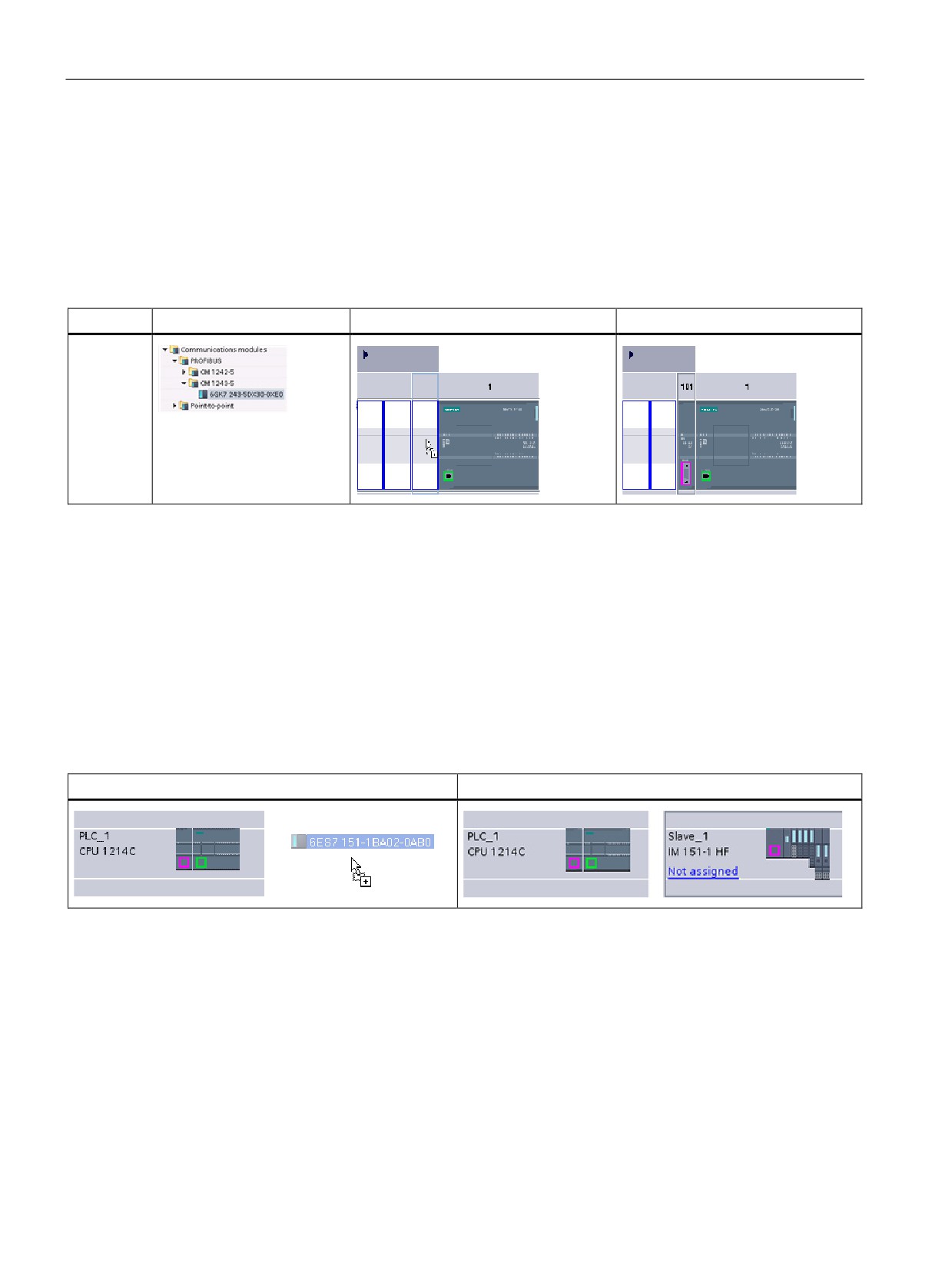
In the "Devices and networks" portal, use the hardware catalog to add PROFIBUS modules
to the CPU. These modules are connected to the left side of the CPU. To insert a module
into the hardware configuration, select the module in the hardware catalog and either
double-click or drag the module to the highlighted slot.
Table 7- 7
Adding a PROFIBUS CM 1243-5 (DP master) module to the device configuration
Module
Select the module
Insert the module
Result
CM 1243-5
(DP mas-
ter)
Use the hardware catalog to add DP slaves as well. For example, to add an ET200 S DP
slave, in the Hardware Catalog, expand the following containers:
● Distributed I/O
● ET200 S
● Interface modules
● PROFIBUS
Next, select "6ES7 151-1BA02-0AB0" (IM151-1 HF) from the list of part numbers, and add
the ET200 S DP slave as shown in the figure below.
Table 7- 8
Adding an ET200 S DP slave to the device configuration
Insert the DP slave
Result
160
Easy to communicate between devices
7.6 PROFIBUS
7.6.4
Assigning PROFIBUS addresses to the CM 1243-5 module and DP slave
Configuring the PROFIBUS interface
After you configure logical network connections between two PROFIBUS devices, you can
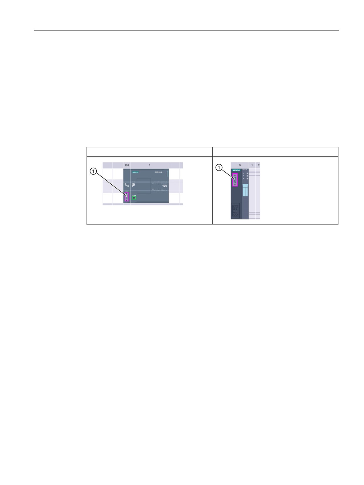
configure parameters for the PROFIBUS interfaces. To do so, click the purple PROFIBUS
box on the CM 1243-5 module, and the "Properties" tab in the inspector window displays the
PROFIBUS interface. The DP slave PROFIBUS interface is configured in the same manner.
Table 7- 9
Configuring the CM 1243-5 (DP master) module and ET200 S DP slave PROFIBUS in-
terfaces
CM 1243-5 (DP master) module
ET200 S DP slave
① PROFIBUS port
Assigning the PROFIBUS address
In a PROFIBUS network, each device is assigned a PROFIBUS address. This address can
range from 0 through 127, with the following exceptions:
● Address 0: Reserved for network configuration and/or programming tools attached to the
bus
● Address 1: Reserved by Siemens for the first master
● Address 126: Reserved for devices from the factory that do not have a switch setting and
must be re-addressed through the network
● Address 127: Reserved for broadcast messages to all devices on the network and may
not be assigned to operational devices
Thus, the addresses that may be used for PROFIBUS operational devices are 2 through
125.
161
Easy to communicate between devices
7.6 PROFIBUS
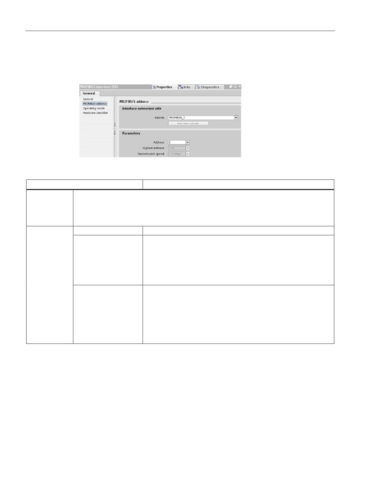
In the Properties window, select the "PROFIBUS address" configuration entry. STEP 7
displays the PROFIBUS address configuration dialog, which is used to assign the
PROFIBUS address of the device.
Table 7- 10 Parameters for the PROFIBUS address
Parameter
Description
Subnet
Name of the Subnet to which the device is connected. Click the "Add new subnet" button to create a
new subnet. "Not connected" is the default. Two connection types are possible:
• The "Not connected" default provides a local connection.
• A subnet is required when your network has two or more devices.
Parameters
Address
Assigned PROFIBUS address for the device
Highest address
The highest PROFIBUS address is based on the active stations on the
PROFIBUS (for example, DP master). Passive DP slaves independently
have PROFIBUS addresses from 1 to 125 even if the highest PROFIBUS
address is set to 15, for example. The highest PROFIBUS address is rele-
vant for token forwarding (forwarding of the send rights), and the token is
only forwarded to active stations. Specifying the highest PROFIBUS ad-
dress optimizes the bus.
Transmission rate
Transmission rate of the configured PROFIBUS network: The PROFIBUS
transmission rates range from 9.6 Kbits/sec to 12 Mbits/sec. The transmis-
sion rate setting depends on the properties of the PROFIBUS nodes being
used. The transmission rate should not be greater than the rate supported
by the slowest node.
The transmission rate is normally set for the master on the PROFIBUS
network, with all DP slaves automatically using that same transmission rate
(auto-baud).
162
Easy to communicate between devices
7.7 AS-i
7.7
AS-i
The S7-1200 AS-i master CM 1243-2 allows the attachment of an AS-i network to an S7-
1200 CPU.
The actuator/sensor interface, or AS-i, is a single master network connection system for the
lowest level in automation systems. The CM 1243-2 serves as the AS-i master for the
network. Using a single AS-i cable, sensors and actuators (AS-i slave devices) can be
connected to the CPU through the CM 1243-2. The CM 1243-2 handles all AS-i network
coordination and relays data and status information from the actuators and sensors to the
CPU through the I/O addresses assigned to the CM 1243-2. You can access binary or
analog values depending on the slave type. The AS-i slaves are the input and output
channels of the AS-i system and are only active when called by the CM 1243-2.
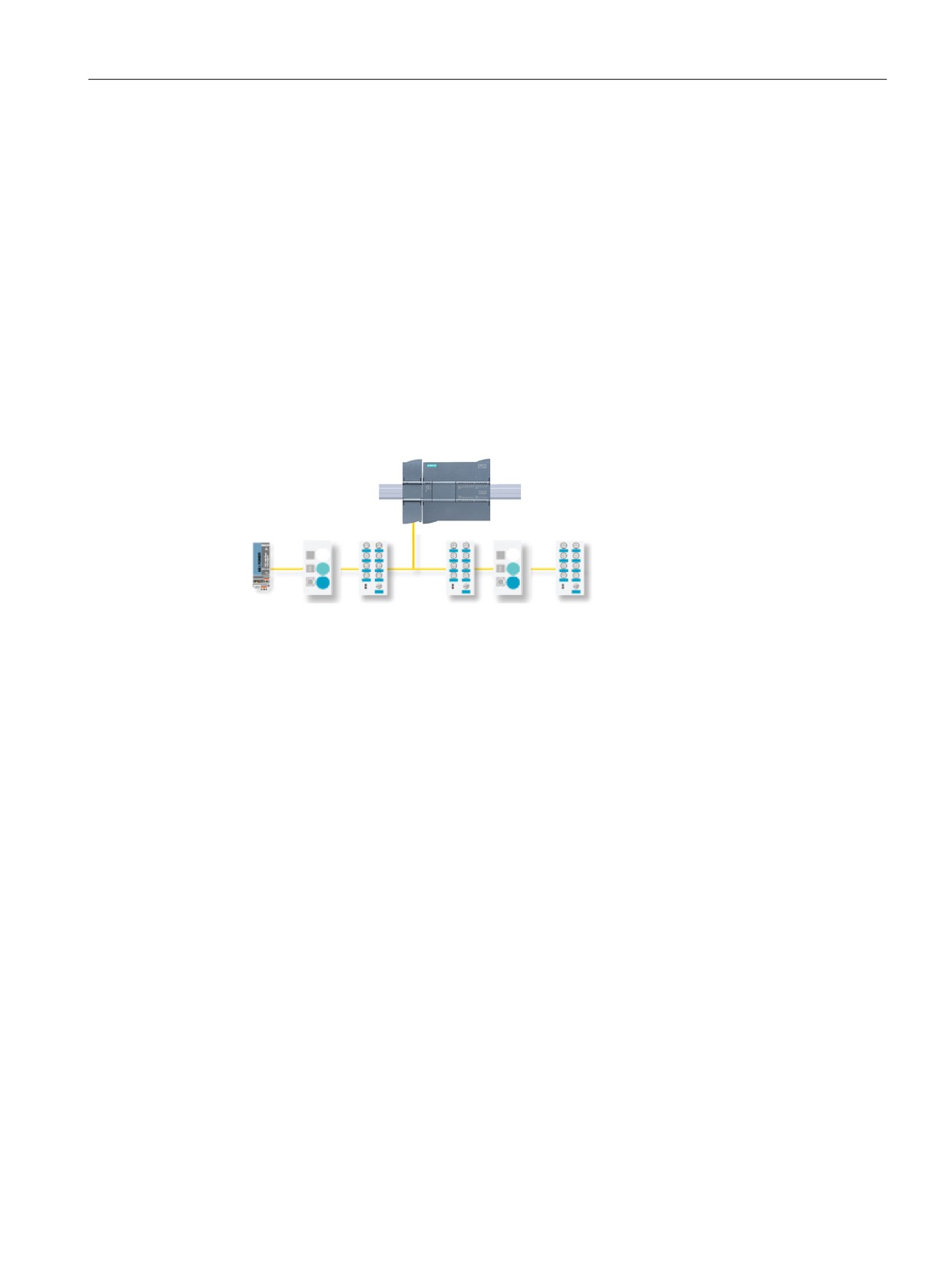
In the figure below, the S7-1200 is an AS-i master controlling AS-i I/O module digital/analog
slave devices.
163
Easy to communicate between devices
7.7 AS-i
7.7.1
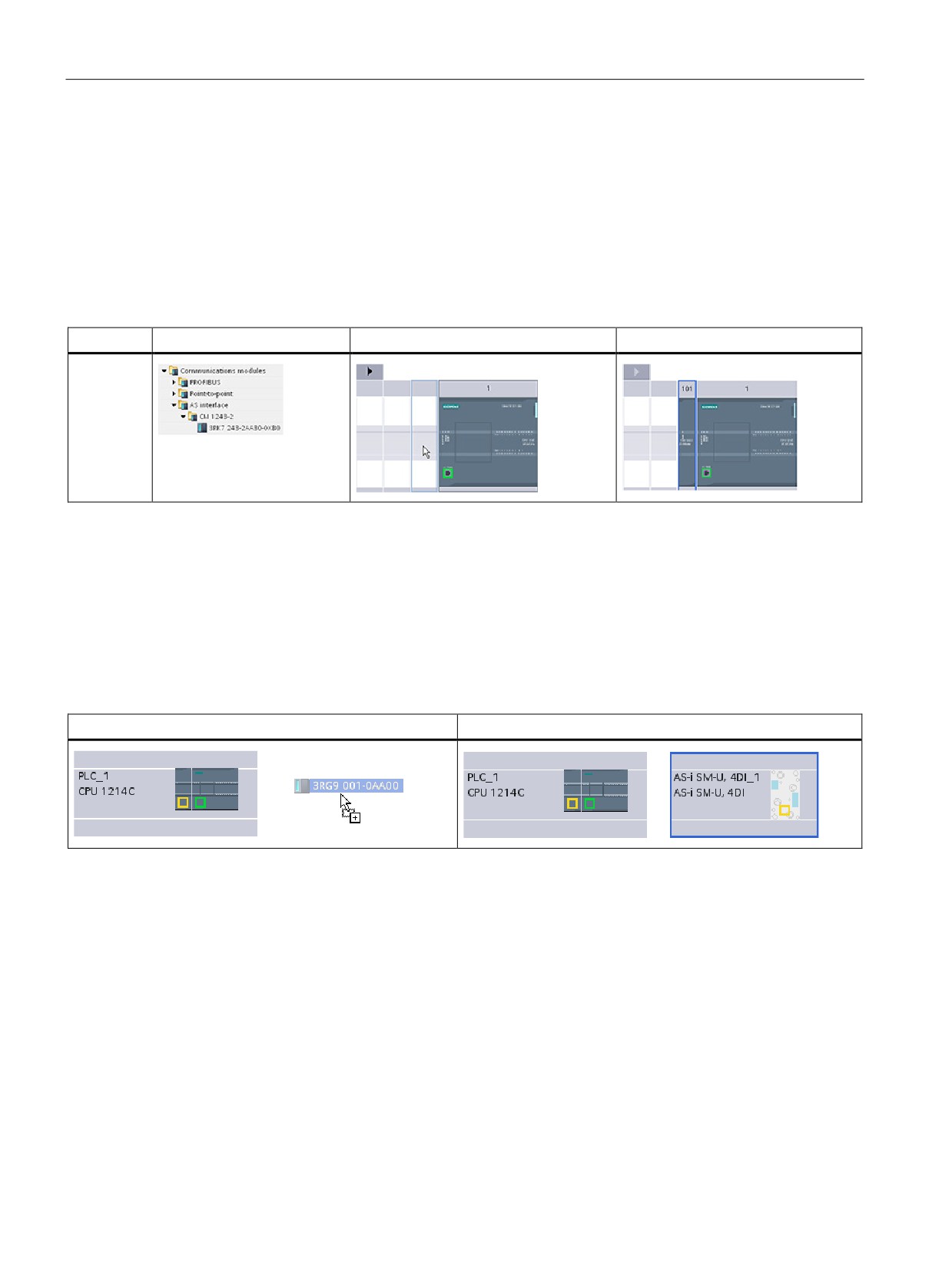
Adding the AS-i master CM 1243-2 and AS-i slave
Use the hardware catalog to add AS-i master CM1243-2 modules to the CPU. These
modules are connected to the left side of the CPU, and a maximum of three AS-i master
CM1243-2 modules can be used. To insert a module into the hardware configuration, select
the module in the hardware catalog and either double-click or drag the module to the
highlighted slot.
Table 7- 11 Adding an AS-i master CM1243-2 module to the device configuration
Module
Select the module
Insert the module
Result
CM 1243-2
AS-i Mas-
ter
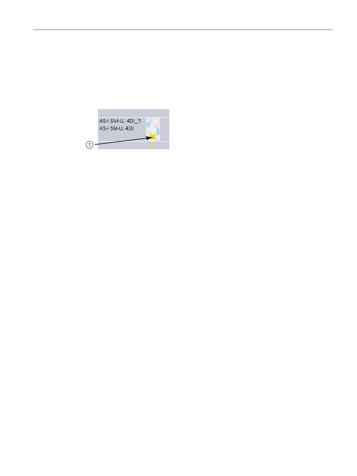
Use the hardware catalog to add AS-i slaves as well. For example, to add an "I/O module,
compact, digital, input" slave, in the Hardware Catalog, expand the following containers:
● Field devices
● AS-Interface slaves
Next, select "3RG9 001-0AA00" (AS-i SM-U, 4DI) from the list of part numbers, and add the
"I/O module, compact, digital, input" slave as shown in the figure below.
Table 7- 12 Adding an AS-i slave to the device configuration
Insert the AS-i slave
Result
164
Easy to communicate between devices
7.7 AS-i
7.7.2
Assigning an AS-i address to an AS-i slave
Configuring the AS-i slave interface
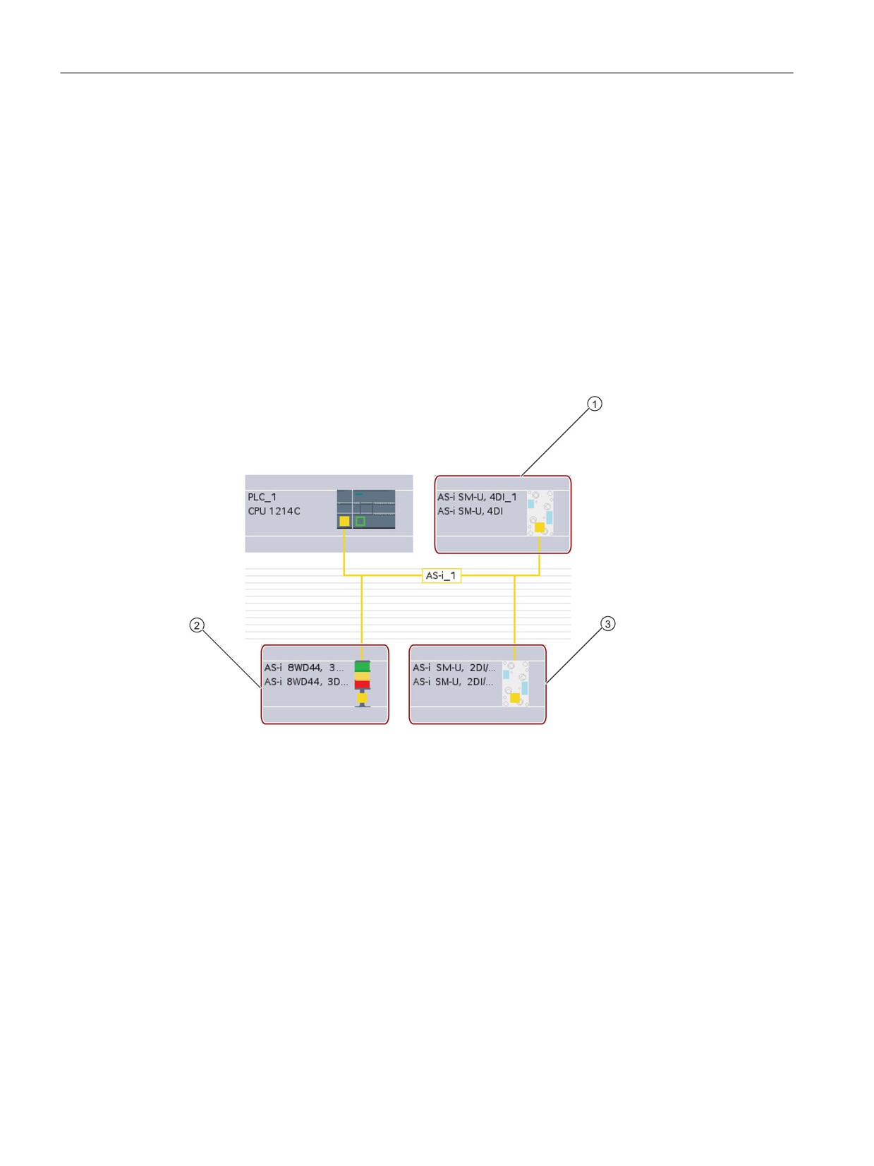
To configure parameters for the AS-i interface, click the yellow AS-i box on the AS-i slave,
and the "Properties" tab in the inspector window displays the AS-i interface.
① AS-i port
165
Easy to communicate between devices
7.7 AS-i
Assigning the AS-i slave address
In an AS-i network, each device is assigned an AS-i slave address. This address can range
from 0 through 31; however, address 0 is reserved only for new slave devices. The slave
addresses are 1(A or B) to 31(A or B) for a total of up to 62 slave devices.
"Standard" AS-i devices use the entire address, having a number address without the A or B
designation. "A/B node" AS-i devices use the A or B portion of each address, enabling each
of the 31 addresses to be used twice. The address space range is 1A to 31A plus 1B to 31B.
Any address in the range of 1 - 31 can be assigned to an AS-i slave device; in other words, it
does not matter whether the slaves begin with address 21 or whether the first slave is
actually given the address 1.
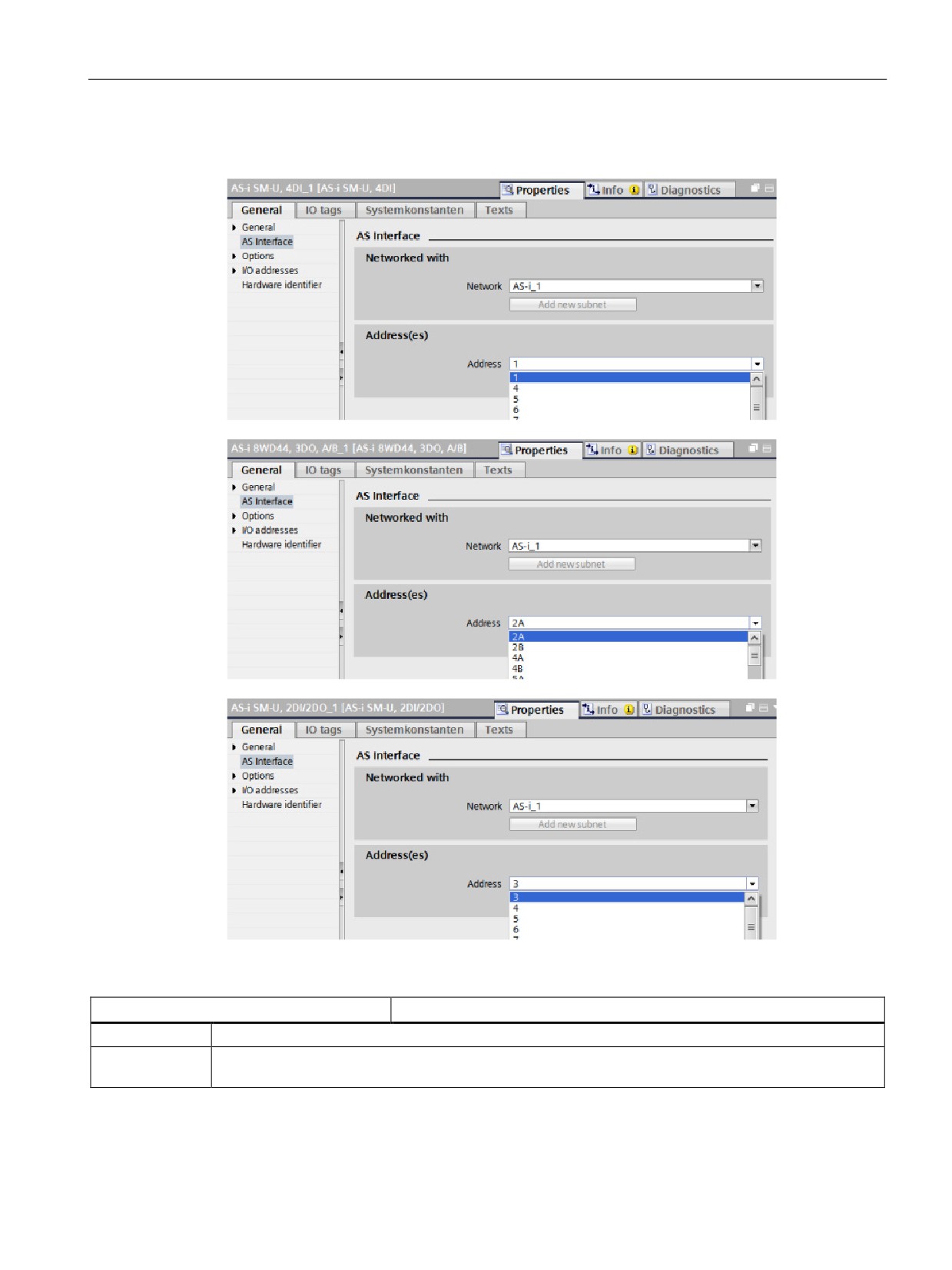
In the example below, three AS-i devices have been addressed as "1" (a standard type
device), "2A" (an A/B node type device), and "3" (a standard type device):
① AS-i slave address 1; Device: AS-i SM-U, 4DI; article number: 3RG9 001-0AA00
② AS-i slave address 2A; Device: AS-i 8WD44, 3DO, A/B; article number: 8WD4 428-0BD
③ AS-i slave address 3; Device: AS-i SM-U, 2DI/2DO; article number: 3RG9 001-0AC00
166
Easy to communicate between devices
7.7 AS-i
Enter the AS-i slave address here:
Table 7- 13 Parameters for the AS-i interface
Parameter
Description
Network
Name of the network to which the device is connected
Address(es)
Assigned AS-i address for the slave device in range of 1(A or B) to 31(A or B) for a total of up to 62
slave devices
167

Easy to communicate between devices
7.8 S7 communication
7.8
S7 communication
7.8.1
GET and PUT instructions
You can use the GET and PUT instructions to communicate with S7 CPUs through
PROFINET and PROFIBUS connections. This is only possible if the "Permit access with
PUT/GET communication" function is activated for the partner CPU in the "Protection"
property of the local CPU properties:
● Accessing data in a remote CPU: An S7-1200 CPU can only use absolute addresses in
the ADDR_x input field to address variables of remote CPUs (S7-200/300/400/1200).
● Accessing data in a standard DB: An S7-1200 CPU can only use absolute addresses in
the ADDR_x input field to address DB variables in a standard DB of a remote S7 CPU.
● Accessing data in an optimized DB: An S7-1200 CPU cannot access DB variables in an
optimized DB of a remote S7-1200 CPU.
● Accessing data in a local CPU: An S7-1200 CPU can use either absolute or symbolic
addresses as inputs to the RD_x or SD_x input fields of the GET or PUT instruction,
respectively.
STEP 7 automatically creates the DB when you insert the instruction.
Note
To ensure data consistency, always evaluate when the operation has been completed
(NDR = 1 for GET, or DONE = 1 for PUT) before accessing the data or initiating another
read or write operation.
Note
V4.0 CPU program GET/PUT operation is not automatically enabled
A V3.0 CPU program GET/PUT operation is automatically enabled in a V4.0 CPU.
However, a V4.0 CPU program GET/PUT operation in a V4.0 CPU is not automatically
enabled. You must go the CPU "Device configuration", inspector window "Properties"tab,
"Protection" property to enable GET/PUT access (Page 87).
168
Easy to communicate between devices
7.8 S7 communication
7.8.2
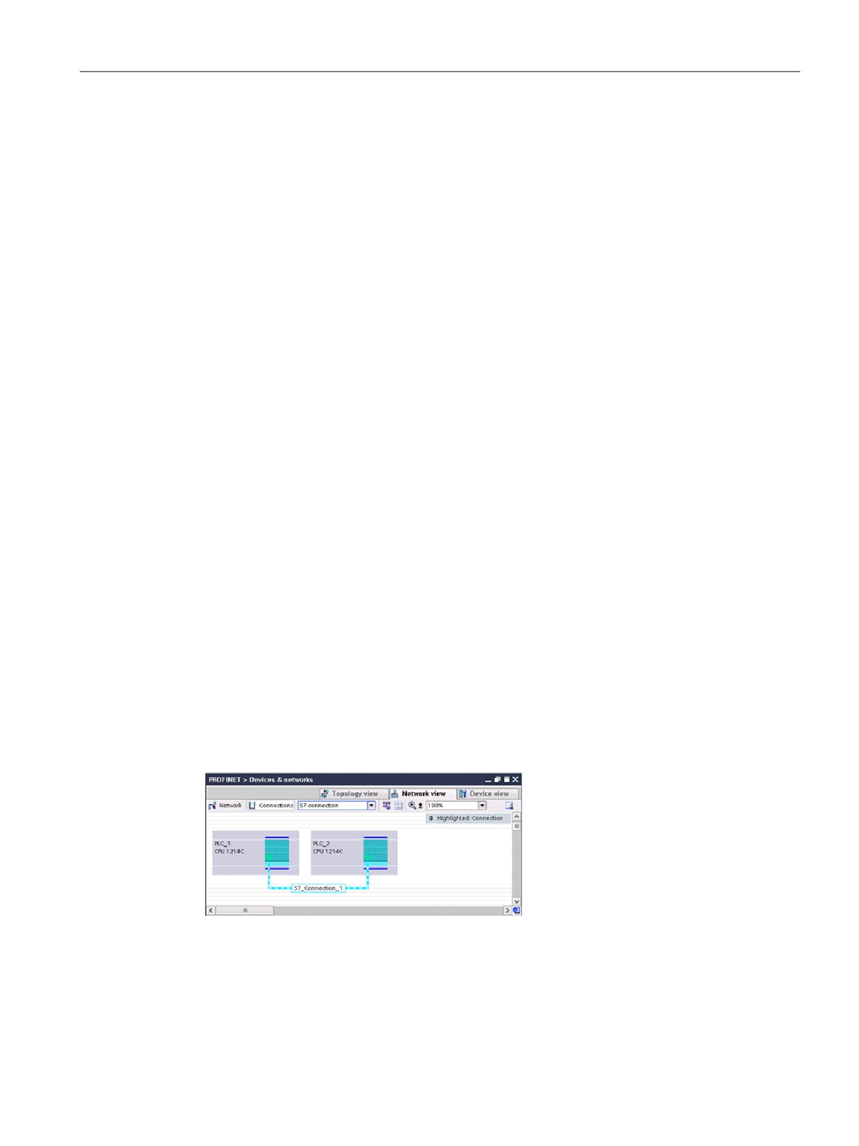
Creating an S7 connection
Connection mechanisms
To access remote connection partners with PUT/GET instructions, the user must also have
permission.
By default, the "Permit access with PUT/GET communication" option is not enabled. In this
case, read and write access to CPU data is only possible for communication connections
that require configuration or programming both for the local CPU and for the communication
partner. Access through BSEND/BRCV instructions is possible, for example.
Connections for which the local CPU is only a server (meaning that no
configuration/programming of the communication with the communication partner exists at
the local CPU), are therefore not possible during operation of the CPU, for example:
● PUT/GET, FETCH/WRITE or FTP access through communication modules
● PUT/GET access from other S7 CPUs
● HMI access through PUT/GET communication
If you want to allow access to CPU data from the client side, that is, you do not want to
restrict the communication services of the CPU, you can configure the access protection for
the S7-1200 CPU (Page 87) for this level of security.
Connection types
The connection type that you select creates a communication connection to a partner
station. The connection is set up, established, and automatically monitored.
In the Devices and Networks portal, use the "Network view" to create the network
connections between the devices in your project. First, click the "Connections" tab, and then
select the connection type with the dropdown, just to the right (for example, an S7
connection). Click the green (PROFINET) box on the first device, and drag a line to the
PROFINET box on the second device. Release the mouse button and your PROFINET
connection is joined.
Refer to "Creating a network connection" (Page 140) for more information.
Click the "Highlighted: Connection" button to access the "Properties" configuration dialog of
the communication instruction.
169
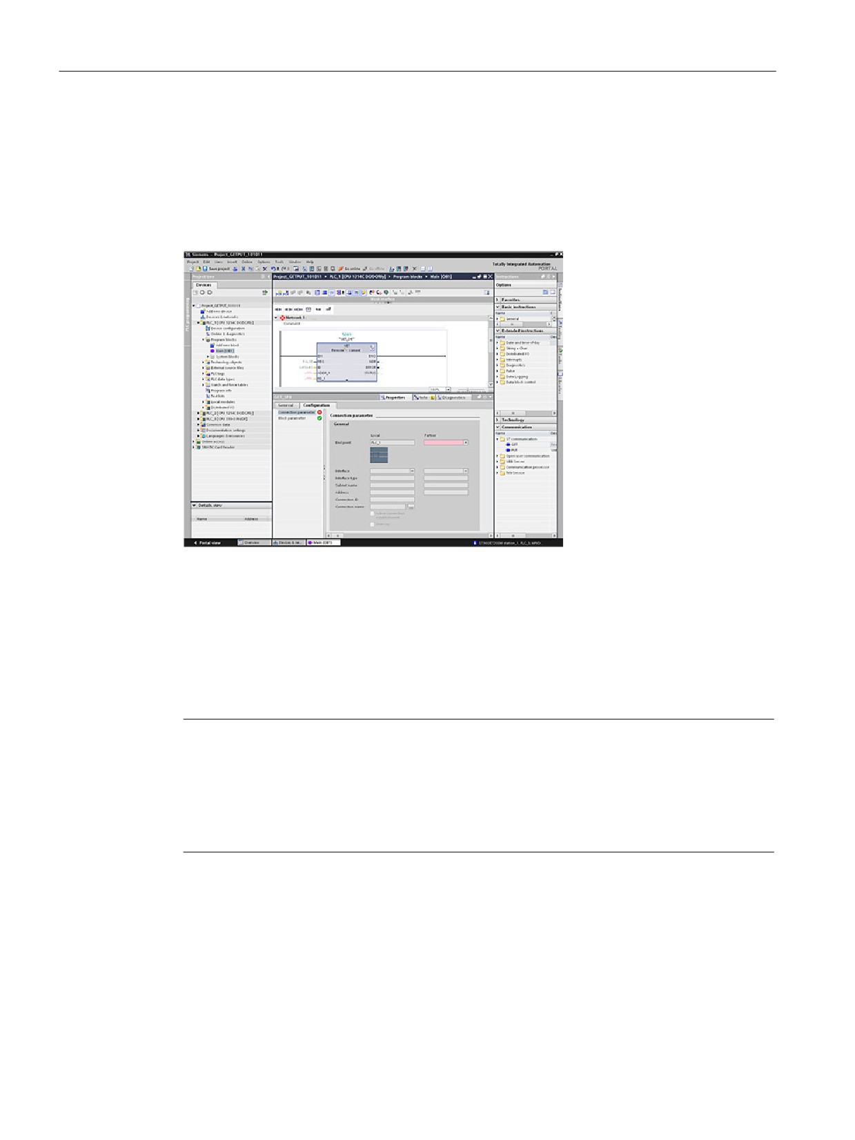
Easy to communicate between devices
7.8 S7 communication
7.8.3
GET/PUT connection parameter assignment
The GET/PUT instructions connection parameter assignment is a user aid for configuring S7
CPU-CPU communication connections.
After inserting a GET or PUT block, the GET/PUT instructions connection parameter
assignment is started:
The inspector window displays the properties of the connection whenever you have selected
any part of the instruction. Specify the communication parameters in the "Configuration" tab
of the "Properties" for the communication instruction.
After inserting a GET or PUT block, the "Configuration" tab automatically appears and the
"Connection parameters" page is immediately shown. This page allows the user to configure
the necessary S7 connection and to configure the parameter "Connection ID" that is
referenced by the block parameter "ID". A "Block parameters" page allows the user to
configure additional block parameters.
Note
V4.0 CPU program GET/PUT operation is not automatically enabled
A V3.0 CPU program GET/PUT operation is automatically enabled in a V4.0 CPU.
However, a V4.0 CPU program GET/PUT operation in a V4.0 CPU is not automatically
enabled. You must go the CPU "Device configuration", inspector window "Properties"tab,
"Protection" property to enable GET/PUT access (Page 87).
170
Easy to communicate between devices
7.9 GPRS
7.9
GPRS
7.9.1
Connection to a GSM network
IP-based WAN communication via GPRS
Using the CP 1242-7 communications processor, the S7-1200 can be connected to GSM
networks. The CP 1242-7 allows WAN communication from remote stations with a control
center and inter-station communication.
Inter-station communication is possible only via a GSM network. For communication
between a remote station and a control room, the control center must have a PC with
Internet access.
The CP 1242-7 supports the following services for communication via the GSM network:
● GPRS (General Packet Radio Service)
The packet-oriented service for data transmission "GPRS" is handled via the GSM
network.
● SMS (Short Message Service)
The CP 1242-7 can receive and send SMS messages. The communications partner can
be a mobile phone or an S7-1200.
The CP 1242-7 is suitable for use in industry worldwide and supports the following frequency
bands:
●
850 MHz
●
900 MHz
●
1,800 MHz
●
1,900 MHz
171
Easy to communicate between devices
7.9 GPRS
Requirements
The equipment used in the stations or the control center depends on the particular
application.
● For communication with or via a central control room, the control center requires a PC
with Internet access.
● Apart from the station equipment, a remote S7-1200 station with a CP 1242-7 must meet
the following requirements to be able to communicate via the GSM network:
- A contract with a suitable GSM network provider
If GPRS is used, the contract must allow the use of the GPRS service.
If there is to be direct communication between stations only via the GSM network, the
GSM network provider must assign a fixed IP address to the CPs. In this case,
communication between stations is not via the control center.
- The SIM card belonging to the contract
The SIM card is inserted in the CP 1242-7.
- Local availability of a GSM network in the range of the station
172
Easy to communicate between devices
7.9 GPRS
7.9.2
Applications of the CP 1242-7
The CP 1242-7 can be used for the following applications:
Telecontrol applications
●
Sending messages by SMS
Via the CP 1242-7, the CPU of a remote S7-1200 station can receive SMS messages
from the GSM network or send messages by SMS to a configured mobile phone or an
S7-1200.
●
Communication with a control center
Remote S7-1200 stations communicate via the GSM network and the Internet with a
telecontrol server in the master station. For data transfer using GPRS, the
"TELECONTROL SERVER BASIC" application is installed on the telecontrol server in the
master station. The telecontrol server communicates with a higher-level central control
system using the integrated OPC server function.
●
Communication between S7-1200 stations via a GSM network
Communication between remote stations with a CP 1242-7 can be handled in two
different ways:
- Inter-station communication via a master station
In this configuration, a permanent secure connection between S7-1200 stations that
communicate with each other and the telecontrol server is established in the master
station. Communication between the stations is via the telecontrol server. The
CP 1242-7 operates in "Telecontrol" mode.
- Direct communication between the stations
For direct communication between stations without the detour via the master station,
SIM cards with a fixed IP address are used that allow the stations to address each
other directly. The possible communications services and security functions (for
example VPN) depend on what is offered by the network provider. The CP 1242-7
operates in "GPRS direct" mode.
TeleService via GPRS
A TeleService connection can be established between an engineering station with STEP 7
and a remote S7-1200 station with a CP 1242-7 via the GSM network and the Internet. The
connection runs from the engineering station via a telecontrol server or a TeleService
gateway that acts as an intermediary forwarding frames and establishing the authorization.
These PCs use the functions of the "TELECONTROL SERVER BASIC" application.
You can use the TeleService connection for the following purposes:
● Downloading configuration or program data from the STEP 7 project to the station
● Querying diagnostics data on the station
173
Easy to communicate between devices
7.9 GPRS
7.9.3
Other properties of the CP-1242-7
Other services and functions of the CP 1242-7
● Time-of-day synchronization of the CP via the Internet
You can set the time on the CP as follows:
- In "Telecontrol" mode, the time of day is transferred by the telecontrol server. The CP
uses this to set its time.
- In "GPRS direct" mode, the CP can request the time using SNTP.
To synchronize the CPU time, you can read out the current time from the CP using a
block.
● Interim buffering of messages to be sent if there are connection problems
● Increased availability thanks to the option of connecting to a substitute telecontrol server
● Optimized data volume (temporary connection)
As an alternative to a permanent connection to the telecontrol server, the CP can be
configured in STEP 7 with a temporary connection to the telecontrol server. In this case,
a connection to the telecontrol server is established only when required.
● Logging the volume of data
The volumes of data transferred are logged and can be evaluated for specific purposes.
174
Easy to communicate between devices
7.9 GPRS
7.9.4
Configuration and electrical connections
Configuration and module replacement
To configure the module, the following configuration tool is required:
STEP 7 version V11.0 SP1 or higher
For STEP 7 V11.0 SP1, you also require support package "CP 1242-7" (HSP0003001).
For process data transfer using GPRS, use the telecontrol communications instructions in
the user program of the station.
The configuration data of the CP 1242-7 is stored on the local CPU. This allows simple
replacement of the CP when necessary.
You can insert up to three modules of the CP 1242-7 type per S7-1200. This, for example,
allows redundant communications paths to be established.
Electrical connections
● Power supply of the CP 1242-7
The CP has a separate connection for the external 24 VDC power supply.
● Wireless interface for the GSM network
An extra antenna is required for GSM communication. This is connected via the SMA
socket of the CP.
7.9.5
Further information
Further information
The CP 1242-7 manual contains detailed information. You will find this on the Internet on the
pages of Siemens Industrial Automation Customer Support under the following entry ID:
175
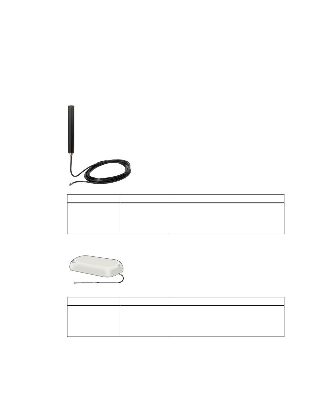
Easy to communicate between devices
7.9 GPRS
7.9.6
Accessories
The ANT794-4MR GSM/GPRS antenna
The following antennas are available for use in GSM/GPRS networks and can be installed
both indoors and outdoors:
● Quadband antenna ANT794-4MR
Short name
Order no.
Explanation
ANT794-4MR
6NH9 860-1AA00
Quadband antenna (900, 1800/1900 MHz, UMTS);
weatherproof for indoor and outdoor areas; 5 m
connecting cable connected permanently to the
antenna; SMA connector, including installation
bracket, screws, wall plugs
● Flat antenna ANT794-3M
Short name
Order no.
Explanation
ANT794-3M
6NH9 870-1AA00
Flat antenna (900, 1800/1900 MHz); weatherproof
for indoor and outdoor areas; 1.2 m connecting cable
connected permanently to the antenna; SMA con-
nector, including adhesive pad, screws mounting
possible
The antennas must be ordered separately.
176
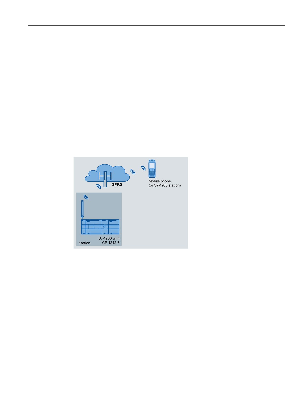
Easy to communicate between devices
7.9 GPRS
7.9.7
Reference to GSM antenna manual
Further information
You will find detailed information in the device manual. You will find this on the Internet on
the pages of Siemens Industrial Automation Customer Support under the following entry ID:
7.9.8
Configuration examples for telecontrol
Below, you will find several configuration examples for stations with a CP 1242-7.
Sending messages by SMS
A SIMATIC S7-1200 with a CP 1242-7 can send messages by SMS to a mobile phone or a
configured S7-1200 station.
177
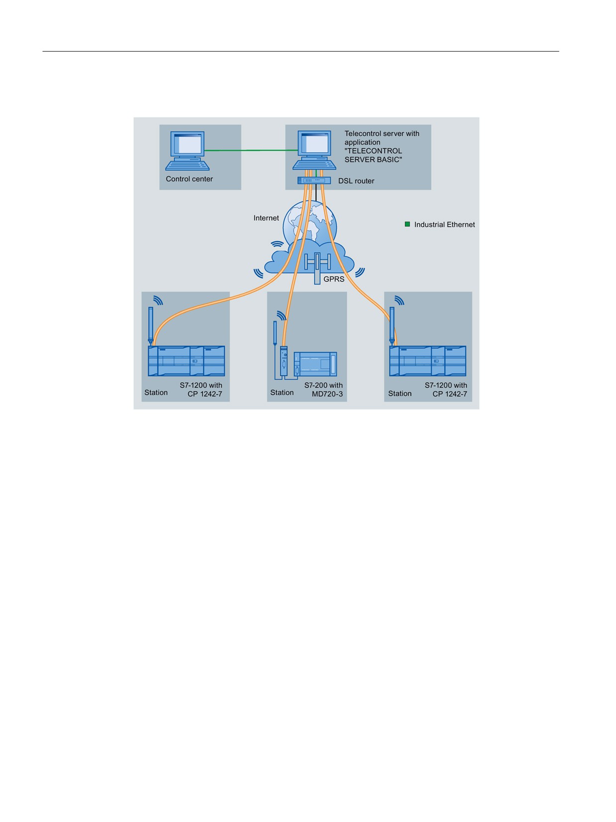
Easy to communicate between devices
7.9 GPRS
Telecontrol by a control center
Figure 7-1
Communication between S7-1200 stations and a control center
In telecontrol applications, SIMATIC S7-1200 stations with a CP 1242-7 communicate with a
control center via the GSM network and the Internet. The "TELECONTROL SERVER
BASIC" (TCSB) application is installed on the telecontrol server in the master station. This
results in the following use cases:
● Telecontrol communication between station and control center
In this use case, data from the field is sent by the stations to the telecontrol server in the
master station via the GSM network and Internet. The telecontrol server is used to
monitor remote stations.
● Communication between a station and a control room with OPC client
As in the first case, the stations communicate with the telecontrol server. Using its
integrated OPC server, the telecontrol server exchanges data with the OPC client of the
control room.
The OPC client and telecontrol server can be located on a single computer, for example
when TCSB is installed on a control center computer with WinCC.
● Inter-station communication via a control center
Inter-station communication is possible with S7 stations equipped with a CP 1242-7.
To allow inter-station communication, the telecontrol server forwards the messages of the
sending station to the receiving station.
178
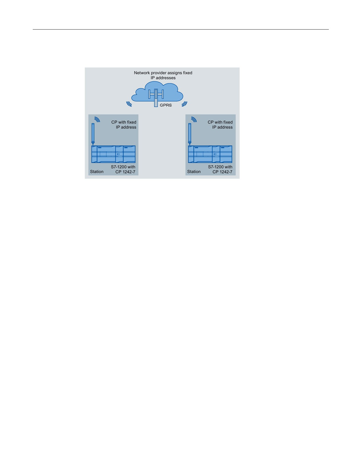
Easy to communicate between devices
7.9 GPRS
Direct communication between stations
Figure 7-2
Direct communication between two S7-1200 stations
In this configuration, two SIMATIC S7-1200 stations communicate directly with each other
using the CP 1242-7 via the GSM network. Each CP 1242-7 has a fixed IP address. The
relevant service of the GSM network provider must allow this.
TeleService via GPRS
In TeleService via GPRS, an engineering station on which STEP 7 is installed communicates
via the GSM network and the Internet with the CP 1242-7 in the S7-1200.
Since a firewall is normally closed for connection requests from the outside, a switching
station between the remote station and the engineering station is required. This switching
station can be a telecontrol server or, if there is no telecontrol server in the configuration, a
TeleService gateway.
179
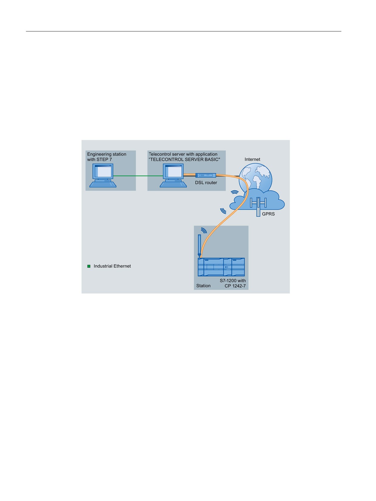
Easy to communicate between devices
7.9 GPRS
TeleService with telecontrol server
The connection runs via the telecontrol server.
● The engineering station and telecontrol server are connected via the Intranet (LAN) or
Internet.
● The telecontrol server and remote station are connected via the Internet and via the GSM
network.
The engineering station and telecontrol server can also be the same computer; in other
words, STEP 7 and TCSB are installed on the same computer.
Figure 7-3
TeleService via GPRS in a configuration with telecontrol server
180
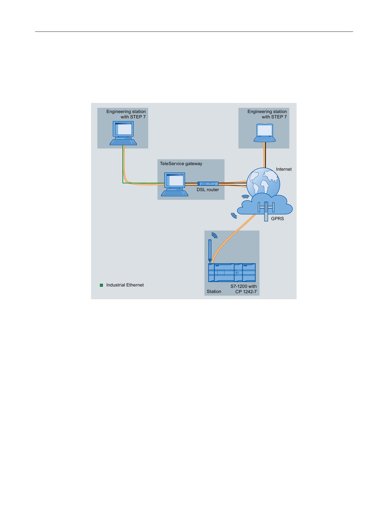
Easy to communicate between devices
7.9 GPRS
TeleService without a telecontrol server
The connection runs via the TeleService gateway.
The connection between the engineering station and the TeleService gateway can be local
via a LAN or via the Internet.
Figure 7-4
TeleService via GPRS in a configuration with TeleService gateway
181
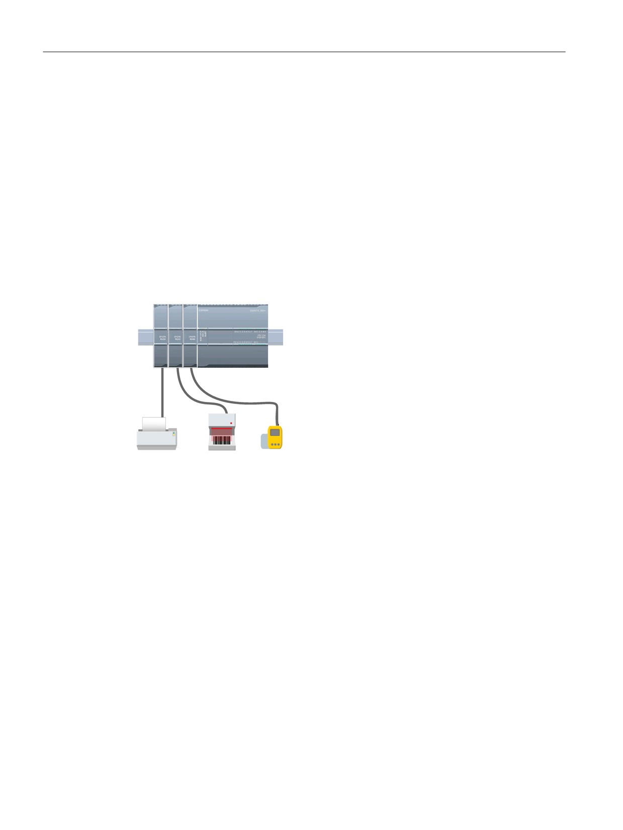
Easy to communicate between devices
7.10 PtP, USS, and Modbus communication protocols
7.10
PtP, USS, and Modbus communication protocols
7.10.1
Point-to-point communication
The CPU supports the following Point-to-Point communication (PtP) for character-based
serial protocols:
● PtP (Page 185)
● USS (Page 186)
● Modbus (Page 188)
PtP provides maximum freedom and flexibility, but requires extensive implementation in the
user program.
PtP enables a wide variety of possibilities:
• The ability to send information directly to an external
device such as a printer
• The ability to receive information from other devices
such as barcode readers, RFID readers, third-party
camera or vision systems, and many other types of
devices
• The ability to exchange information, sending and
receiving data, with other devices such as GPS
devices, third-party camera or vision systems, radio
modems, and many more
This type of PtP communication is serial communica-
tion that uses standard UARTs to support a variety of
baud rates and parity options. The RS232 and
RS422/485 communication modules (CM 1241) and
the RS485 communication board (CB 1241) provide
the electrical interfaces for performing the PtP commu-
nications.
182