Siemens simatic S7-1200. Manual (2015) - page 8
Technical specifications
A.9 Communication interfaces
A.9.4
RS485, RS232 and RS422 communication
A.9.4.1
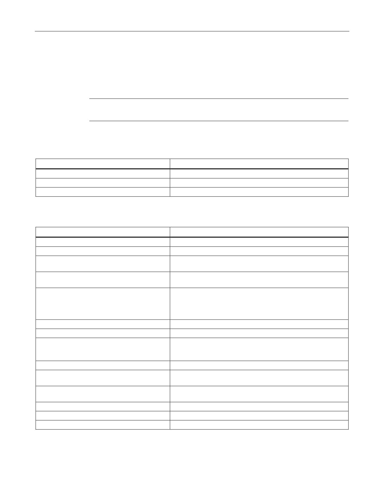
CB 1241 RS485 specifications
Note
To use this CB, your CPU firmware must be V2.0 or higher.
Table A- 65 General specifications
Technical data
CB 1241 RS485
Article number
6ES7 241-1CH30-1XB0
Dimensions W x H x D (mm)
38 x 62 x 21
Weight
40 grams
Table A- 66 Transmitter and receiver
Technical data
CB 1241 RS485
Type
RS485 (2-wire half-duplex)
Common mode voltage range
-7 V to +12 V, 1 second, 3 VRMS continuous
Transmitter differential output voltage
2 V min. at RL = 100 Ω
1.5 V min. at RL = 54 Ω
Termination and bias
10K to +5 V on B, RS485 Pin 3
10K to GND on A, RS485 Pin 4
Optional termination
Short Pin TB to Pin T/RB, effective termination impedance is 127 Ω,
connects to RS485 Pin 3
Short Pin TA to Pin T/RA, effective termination impedance is 127 Ω,
connects to RS485 Pin 4
Receiver input impedance
5.4K Ω min. including termination
Receiver threshold/sensitivity
+/- 0.2 V min., 60 mV typical hysteresis
Isolation
500 VAC, 1 minute
RS485 signal to chassis ground
RS485 signal to CPU logic common
Cable length, shielded
1000 m max.
Baud rate
300 baud, 600 baud, 1.2 kbits, 2.4 kbits, 4.8 kbits, 9.6 kbits (default),
19.2 kbits, 38.4 kbits, 57.6 kbits, 76.8 kbits, 115.2 kbits,
Parity
No parity (default), even, odd, Mark (parity bit always set to 1),
Space (parity bit always set to 0)
Number of stop bits
1 (default), 2
Flow control
Not supported
Wait time
0 to 65535 ms
423
Technical specifications
A.9 Communication interfaces
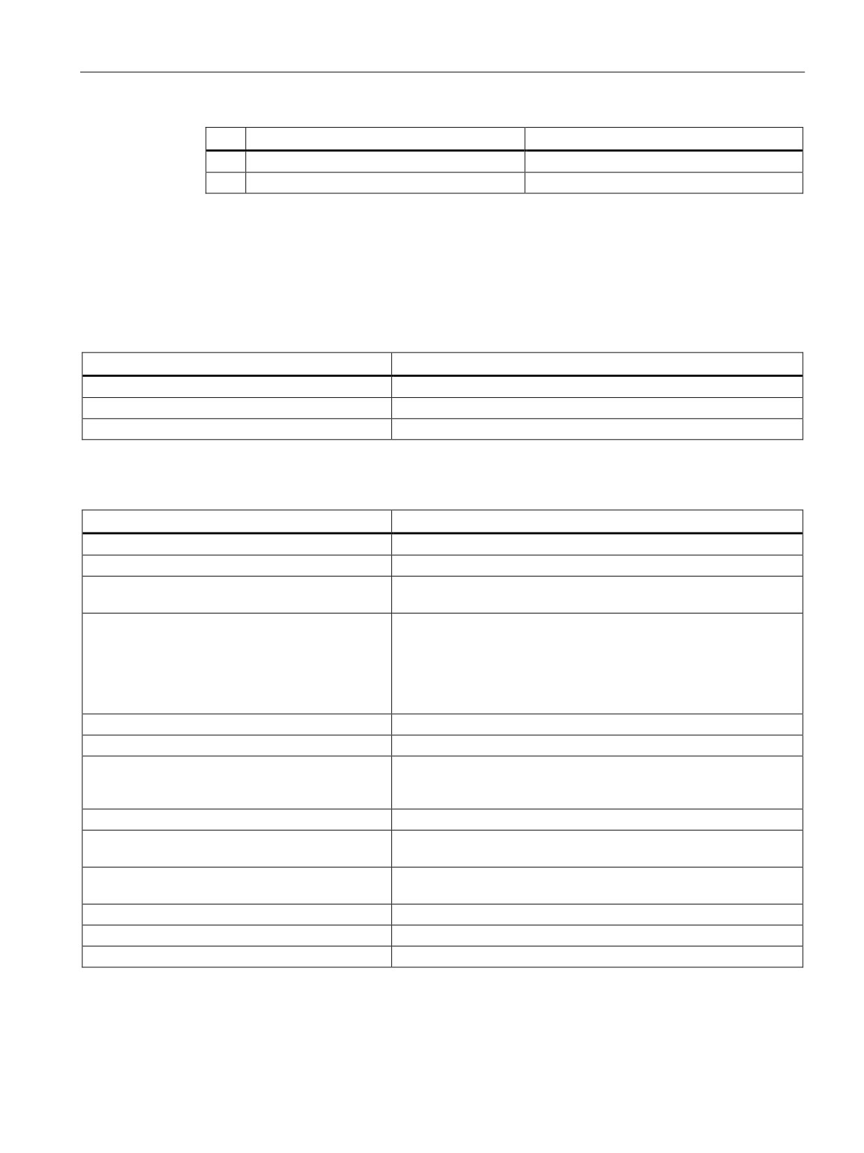
Table A- 67 Power supply
Technical data
CB 1241 RS485
Power loss (dissipation)
1.5 W
Current consumption (SM Bus), max.
50 mA
Current consumption (24 VDC) max.
80 mA
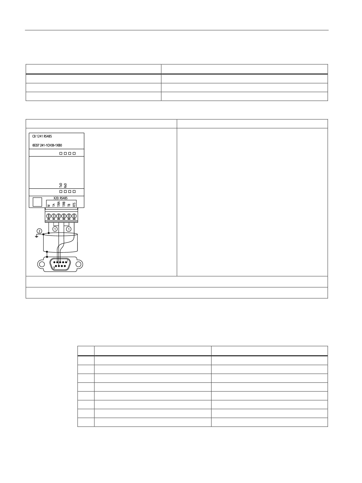
CB 1241 RS485 (6ES7 241-1CH30-1XB0)
① Connect "TA" and TB" as shown to terminate the network. (Terminate only the end devices on the RS485 network.)
② Use shielded twisted pair cable and connect the cable shield to ground.
You terminate only the two ends of the RS485 network. The devices in between the two end
devices are not terminated or biased. See the topic "Biasing and terminating an RS485
network connector"
Table A- 68 Connector pin locations for CB 1241 RS485 (6ES7 241-1CH30-1XB0)
Pin
9-Pin connector
X20
1
RS485 / Logic GND
--
2
RS485 / Not Used
--
3
RS485 / TxD+
3 - T/RB
4
RS485 / RTS
1 - RTS
5
RS485 / Logic GND
--
6
RS485 / 5 V Power
--
7
RS485 / Not used
--
8
RS485 / TxD-
4 - T/RA
424
Technical specifications
A.9 Communication interfaces
Pin
9-Pin connector
X20
9
RS485 / Not Used
--
Shell
7 - M
A.9.4.2
CM 1241 RS422/485 specifications
CM 1241 RS422/485 Specifications
Table A- 69 General specifications
Technical data
CM 1241 RS422/485
Article number
6ES7 241-1CH32-0XB0
Dimensions W x H x H (mm)
30 x 100 x 75
Weight
155 grams
Table A- 70 Transmitter and receiver
Technical data
CM 1241 RS422/485
Type
RS422 or RS485, 9-pin sub D female connector
Common mode voltage range
-7 V to +12 V, 1 second, 3 VRMS continuous
Transmitter differential output voltage
2 V min. at RL = 100 Ω
1.5 V min. at RL = 54 Ω
Termination and bias
10K Ω to +5 V on B, PROFIBUS Pin 3
10K Ω to GND on A, PROFIBUS Pin 8
Internal bias options provided, or no internal bias. In all cases, exter-
nal termination is required, see Biasing and terminating an RS485
network connector and Configuring the RS422 and RS485 in the S7-
1200 Programmable Controller System Manual
Receiver input impedance
5.4K Ω min. including termination
Receiver threshold/sensitivity
+/- 0.2 V min., 60 mV typical hysteresis
Isolation
500 VAC, 1 minute
RS485 signal to chassis ground
RS485 signal to CPU logic common
Cable length, shielded
1000 m max. (baud rate dependent)
Baud rate
300 baud, 600 baud, 1.2 kbits, 2.4 kbits, 4.8 kbits, 9.6 kbits (default),
19.2 kbits, 38.4 kbits, 57.6 kbits, 76.8 kbits, 115.2 kbits,
Parity
No parity (default), even, odd, Mark (parity bit always set to 1),
Space (parity bit always set to 0)
Number of stop bits
1 (default), 2
Flow control
XON/XOFF supported for the RS422 mode
Wait time
0 to 65535 ms
425
Technical specifications
A.9 Communication interfaces
Table A- 71 Power supply
Technical data
CM 1241 RS422/485
Power loss (dissipation)
1.1 W
From +5 VDC
220 mA
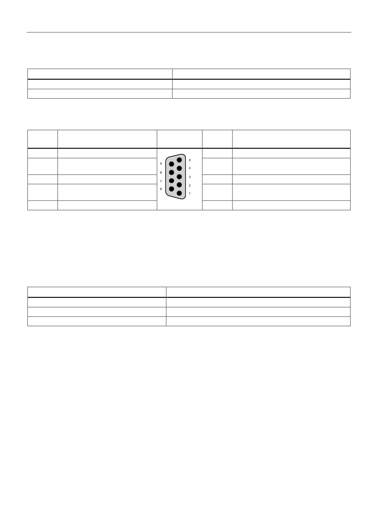
Table A- 72 RS485 or RS422 connector (female)
Pin
Description
Connector
Pin
Description
(female)
1
Logic or communication ground
6 PWR
+5 V with 100 ohm series resistor: Output
2 TxD+ 1
Connected for RS422
7
Not connected
Not used for RS485: Output
3 TxD+
Signal B (RxD/TxD+): Input/Output
8 TXD-
Signal A (RxD/TxD-): Input/Output
4 RTS 2
Request to send (TTL level) Output
9 TXD- 1
Connected for RS422
Not used for RS485: Output
5 GND
Logic or communication ground
SHELL
Chassis ground
1
Pins 2 and 9 are only used as transmit signals for RS422.
2
The RTS is a TTL level signal and can be used to control another half duplex device based on this signal. It is active
when you transmit and is inactive all other times.
A.9.4.3
CM 1241 RS232 specifications
Table A- 73 General specifications
Technical data
CM 1241 RS232
Article number
6ES7 241-1AH32-0XB0
Dimensions (mm)
30 x 100 x 75
Weight
150 grams
426
Technical specifications
A.9 Communication interfaces
Table A- 74 Transmitter and receiver
Technical data
CM 1241 RS232
Type
RS232 (full-duplex)
Transmitter output voltage
+/- 5 V min. at RL = 3K Ω
Transmit output voltage
+/- 15 VDC max.
Receiver input impedance
3 K Ω min.
Receiver threshold/sensitivity
0.8 V min. low, 2.4 max. high
0.5 V typical hysteresis
Receiver input voltage
+/- 30 VDC max.
Isolation
500 VAC, 1 minute
RS 232 signal to chassis ground
RS 232 signal to CPU logic common
Cable length, shielded
10 m max.
Baud rate
300 baud, 600 baud, 1.2 kbits, 2.4 kbits, 4.8 kbits, 9.6 kbits (default),
19.2 kbits, 38.4 kbits, 57.6 kbits, 76.8 kbits, 115.2 kbits,
Parity
No parity (default), even, odd, Mark (parity bit always set to 1),
Space (parity bit always set to 0)
Number of stop bits
1 (default), 2
Flow control
Hardware, software
Wait time
0 to 65535 ms
Table A- 75 Power supply
Technical data
CM 1241 RS232
Power loss (dissipation)
1 W
From +5 VDC
200 mA
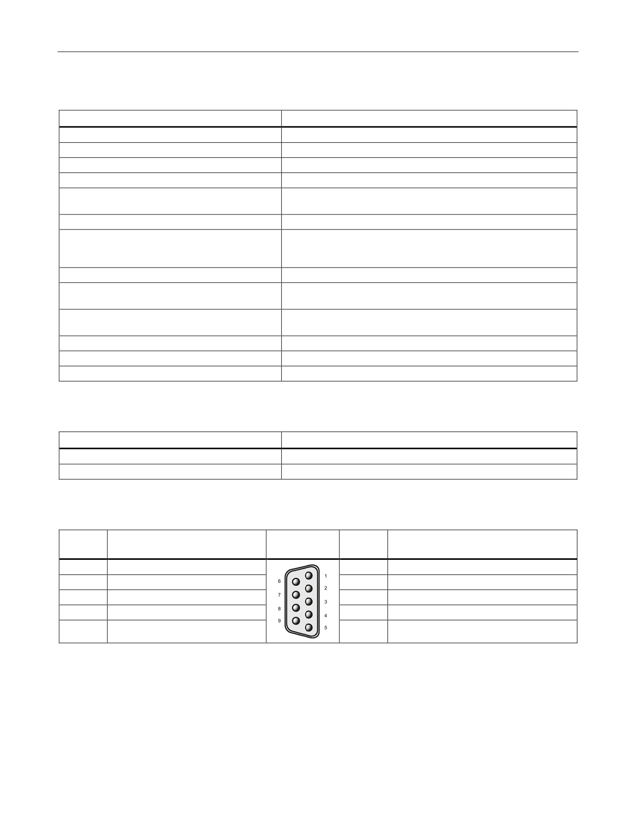
Table A- 76 RS232 connector (male)
Pin
Description
Connector
Pin
Description
(male)
1 DCD
Data carrier detect: Input
6 DSR
Data set ready: Input
2 RxD
Received data from DCE: Input
7 RTS
Request to send: Output
3 TxD
Transmitted data to DCE: Output
8 CTS
Clear to send: Input
4 DTR
Data terminal ready: Output
9 RI
Ring indicator (not used)
5 GND
Logic ground
SHELL
Chassis ground
427
Technical specifications
A.10 Technology modules
A.10
Technology modules
A.10.1
SM 1278 4xIO-Link Master SM
A.10.1.1
SM 1278 4xIO-Link Master signal module specifications
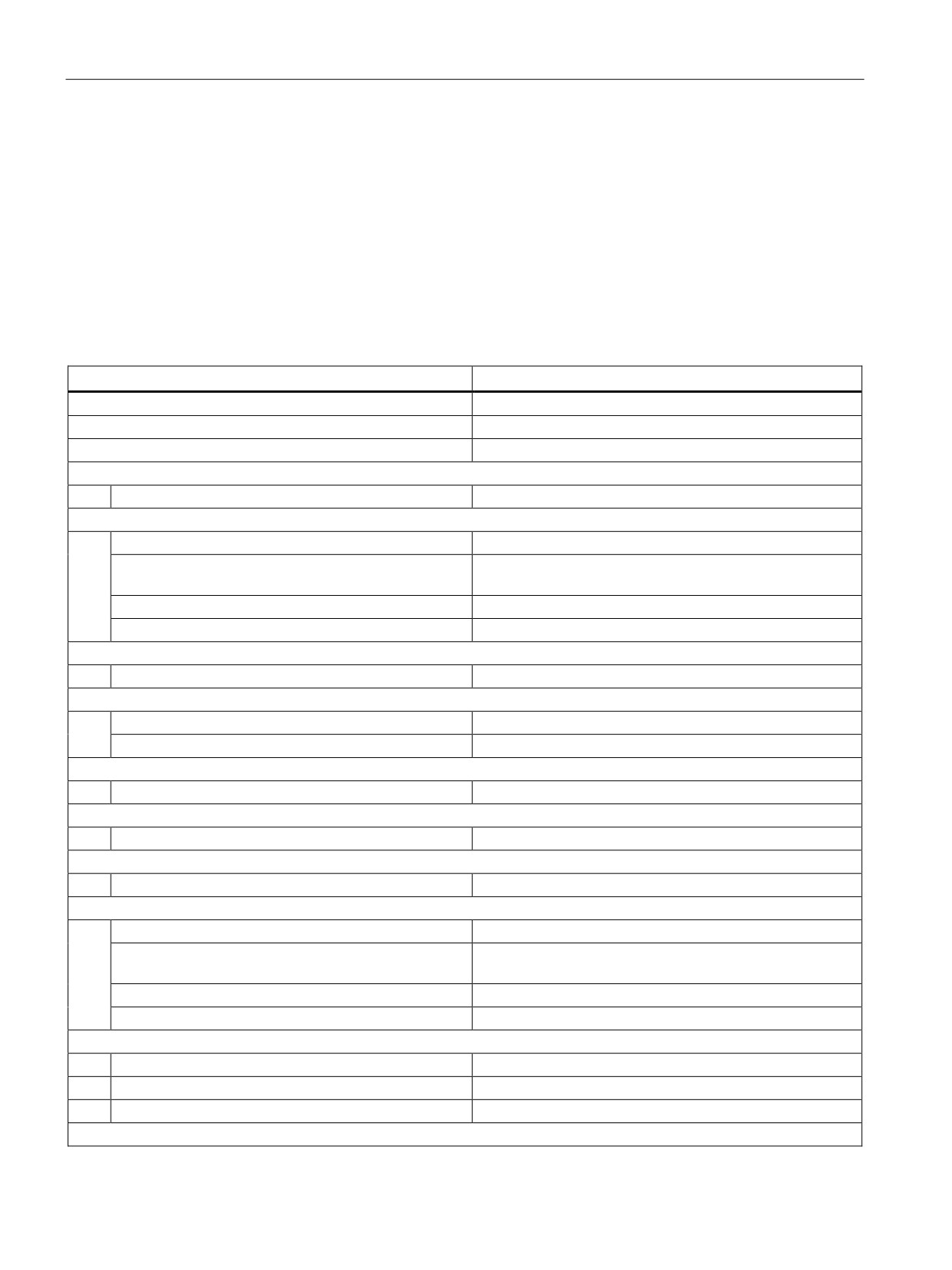
Table A- 77 General specifications
Technical data
SM 1278 4xIO-Link Master signal module
Article number
6ES7 278-4BD32-0XB0
Dimensions W x H x D (mm)
45 x 100 x 75
Weight
150 grams
General information
I&M data
Yes; IM0 to IM3
Supply voltage
Rated voltage (DC)
24 VDC
Valid range low limit (DC)
19.2 V; 20.5 V if IO-Link is used (the supply voltage for
IO-Link devices on the master must be at least 20 V)
Valid range high limit (DC)
28.8 VDC
Polarity reversal protection
Yes
Input current
Current consumption
65 mA; without load
Encoder supply
Number of outputs
4
Output current, rated value
200 mA
Power loss
Power loss, typ.
1 W, excluding port loading
Digital inputs/outputs
Cable length (meters)
20 m, unshielded, max.
SDLC
Cable length (meters)
20 m, unshielded, max.
IO-Link
Number of ports
4
Number of ports which can be controlled at the same
4
time
IO-Link protocol 1.0
Yes
IO-Link protocol 1.1
Yes
Operating mode
IO-Link
Yes
DI
Yes
DQ
Yes; max. 100 mA
Connection of IO-Link devices
428
Technical specifications
A.10 Technology modules
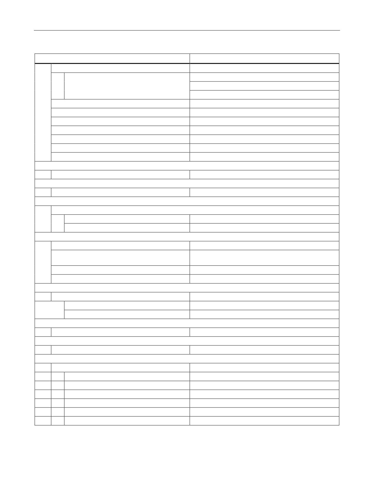
Technical data
SM 1278 4xIO-Link Master signal module
Port type A
Yes
Transmission rate
4.8 kBd (COM1)
38.4 kBd (COM2)
230.4 kBd (COM3)
Cycle time, min.
2 ms, dynamic, dependent on the user data length
Size of process data, input per port
32 bytes; max.
Size of process data, input per module
32 bytes
Size of process data, output per port
32 bytes; max.
Size of process data, output per module
32 bytes
Memory size for device parameters
2 Kbytes
Cable length unshielded, max. (meters)
20 m
Interrupts/diagnostics/status information
Status display
Yes
Interrupts
Diagnostic interrupt
Yes; port diagnostics is only available in IO-Link mode
Diagnostic alarms
Diagnostics
Monitoring of supply voltage
Yes
Short circuit
Yes
Diagostic indicator LED
Monitoring of supply voltage
Yes; flashing red DIAG LED
Channel status display
Yes; per channel one green LED for channel status Qn
(SIO mode) and PORT status Cn (IO-Link mode)
For channel diagnostics
Yes; red Fn LED
For module diagnostics
Yes; green/red DIAG LED
Electrical isolation
Electrical isolation channels
Between the channels
No
Between the channels and the backplane bus
Yes
Permitted potential difference
Between the different circuits
75 VDC / 60 VAC (basic insulation)
Insulation
Insulation tested with
707 VDC (type test)
Ambient conditions
Operating temperature
Min.
-20 °C
Max.
60 °C
Horizontal installation, min.
-20 °C
Horizontal installation, max.
60 °C
Vertical installation, min.
-20 °C
Vertical installation, max.
50 °C
429
Technical specifications
A.10 Technology modules
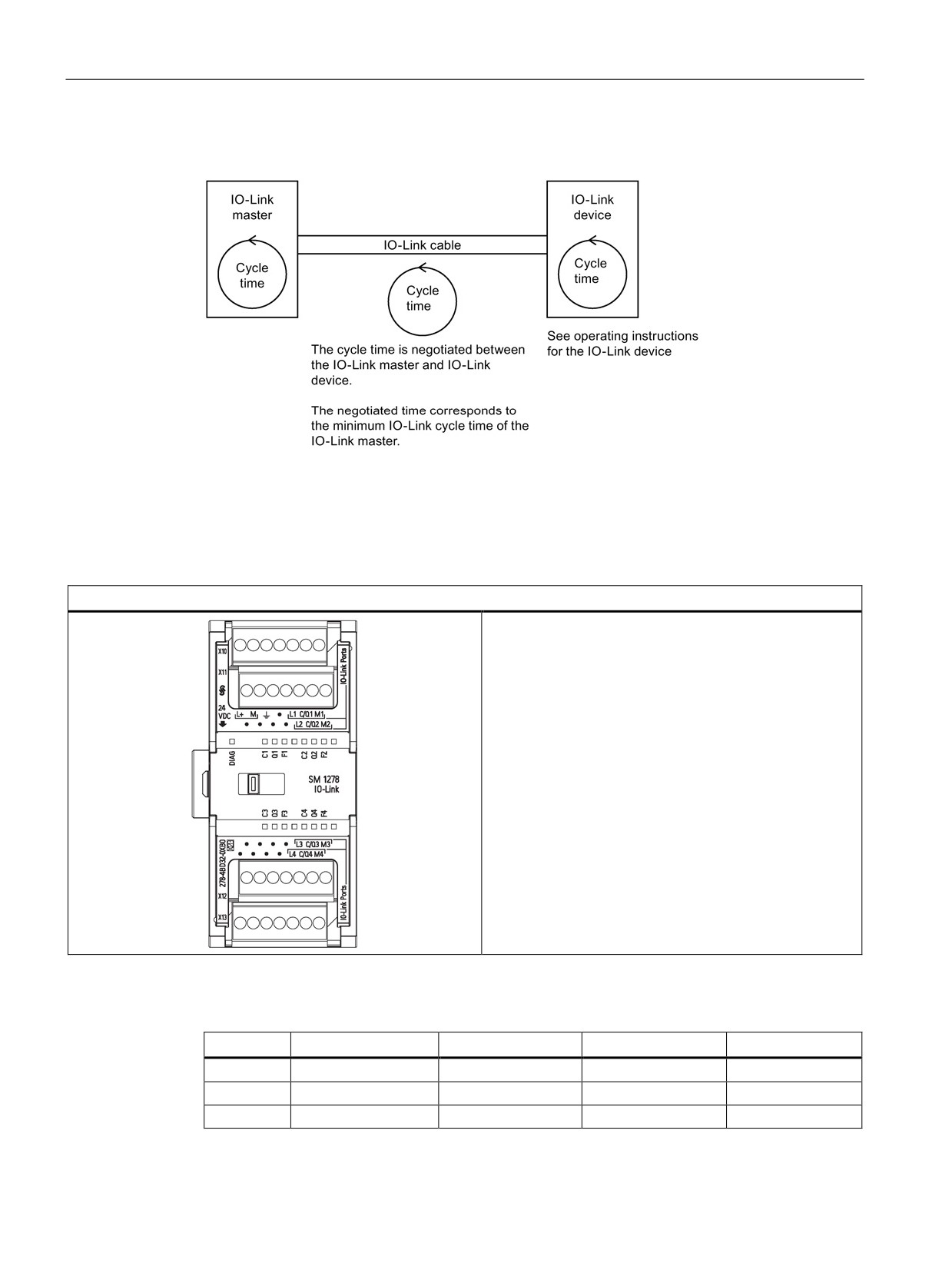
Overview of the response time
A.10.1.2
SM 1278 4xIO-Link Master SM wiring diagrams
Table A- 78 Wiring diagram for the SM 1278 IO-Link Master
SM 1278 IO-Link Master (6ES7 278-4BD32-0XB0)
Table A- 79 Connector pin locations for SM 1278 IO-Link Master (6ES7 278-4BD32-0XB0)
Pin
X10
X11
X12
X13
1
L+ / 24 VDC
No connection
No connection
No connection
2
M / 24 VDC
No connection
No connection
No connection
3
Functional Earth
No connection
No connection
No connection
430

Technical specifications
A.11 Companion products
Pin
X10
X11
X12
X13
4
No connection
No connection
No connection
No connection
5
L1
L2
L3
L4
6
C/Q1
C/QL2
C/Q3
C/QL4
7
ML1
ML2
M3
ML4
A.11
Companion products
A.11.1
PM 1207 power module
The PM 1207 is a power supply module for the SIMATIC S7-1200. It provides the following
features:
● Input 120/230 VAC, output 24 VDC/2.5A
● Article number 6ESP 332-1SH71-4AA0
For more information about this product and for the product documentation, refer to the
product catalog web site for the PM 1207
A.11.2
CSM 1277 compact switch module
The CSM1277 is an Industrial Ethernet compact switch module. It can be used to multiply
the Ethernet interface of the S7-1200 to allow simultaneous communication with operator
panels, programming devices, or other controllers. It provides the following features:
●
4 x RJ45 sockets for connecting to Industrial Ethernet
●
3 pole plug in terminal strip for connection of the external 24 VDC supply on top
● LEDs for diagnostics and status display of Industrial Ethernet ports
● Article number 6GK7 277-1AA00-0AA0
For more information about this product and for the product documentation, refer to the
product catalog web site for the CSM 1277
tab=).
431
Technical specifications
A.11 Companion products
A.11.3
CM CANopen module
The CM CANopen module is a plug-in module between the SIMATIC S7-1200 PLC and any
device running CANopen. The CM CANopen can be configured to be both master or slave.
There are two CM CANopen modules: the CANopen module (article number 021620-B), and
the CANopen (Ruggedized) module (article number 021730-B).
The CANopen module provides the following features:
● Able to connect 3 modules per CPU
● Connects up to 16 CANopen slave nodes
●
256 byte input and 256 byte output per module
●
3 LEDs provide diagnostic information on module, network, and I/O status
● Supports storage of CANopen network configuration in the PLC
● The module is integratable in the hardware catalogue of the TIA Portal configuration suite
● CANopen configuration via included CANopen Configuration Studio (included) or via any
other externanal CANopen configuration tool
● Complies to the CANopen communication profiles CiA 301 rev. 4.2 and the CiA 302 rev.
4.1
● Supports transparent CAN 2.0A for custom protocol handling
● Pre-made function blocks available for each PLC programming in TIA portal
● CM CANopen modules include; DSUB with screw terminals for subnetwork. CM
CANopen configuration studio CD, and USB configuration cable
For more information about this product and for the product documentation, refer to the
product catalog web site for the CM CANopen.
432
Exchanging a V3.0 CPU for a V4.1 CPU
B
B.1
Exchanging a V3.0 CPU for a V4.1 CPU
You can replace your V3.0 CPU with a V4.1 CPU (Page 77) and use your existing STEP 7
project that you designed for the V3.0 CPU. You cannot upgrade a V3.0 CPU to a V4.1 CPU
by firmware update; you must replace the hardware. When you replace a V3.0 CPU with a
V4.1 CPU, you might also want to check for and apply firmware updates (Page 348) to your
connected signal and communication modules.
Note
No device exchange possible from V4.1 to V3.0
You can exchange a V3.0 CPU for a V4.1 CPU, but you cannot exchange a V4.1 CPU for a
V3.0 CPU after you download the configuration. If you want to view or otherwise use your
existing STEP 7 V3.0 project, make an archive of your STEP 7 V3.0 project prior to the
device exchange.
Note that if you have not downloaded the exchanged device configuration, you can undo it.
After downloading, however, you cannot undo the exchange from V3.0 to V4.1.
You need to be aware of some configuration and operational changes between the two CPU
versions:
Organization blocks
With V4.1, you can configure OB execution to be interruptible or non-interruptible (Page 58).
For projects from former V3.0 CPUs, STEP 7 sets all OBs by default to be non-interruptible.
STEP 7 sets all OB priorities (Page 58) to the values they were in the V3.0 CPU STEP 7
project.
You can subsequently change the interruptability or priority settings if you choose.
The Diagnostic error interrupt OB start information references the submodule as a whole if
no diagnostics event is pending.
433
Exchanging a V3.0 CPU for a V4.1 CPU
B.1 Exchanging a V3.0 CPU for a V4.1 CPU
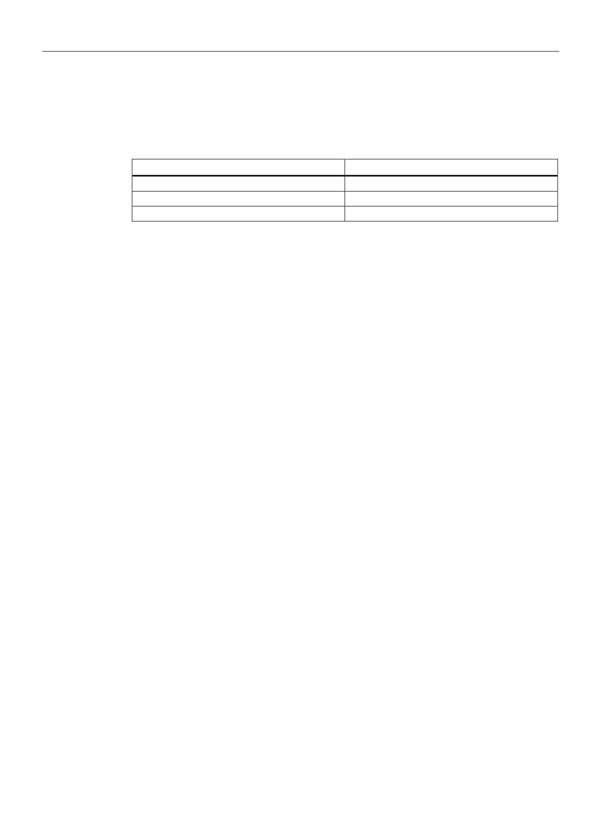
CPU password protection
STEP 7 sets the password protection level (Page 87) for the V4.1 CPU to be the equivalent
password protection level that was set for the V3.0 CPU, and assigns the V3.0 password to
the "Full access (no protection)" password for the V4.1 CPU:
V3.0 protection level
V4.1 access level
No protection
Full access (no protection)
Write protection
Read access
Write/read protection
HMI access
Note that the V4.1 access level "No access (complete protection)" did not exist for V3.0.
Web server
If you use user-defined Web pages in your V3.0 project, store them in your project
installation folder under the subfolder "UserFiles\Webserver" prior to upgrading your project.
If you store your user-defined pages at this location, saving the STEP 7 project will also save
the user-defined Web pages.
If you exchange a V3.0 CPU for a V4.1 CPU, your Web server project setting for activating
the Web server and HTTPS setting will be the same as it was in V3.0. You can then
configure users, privileges, passwords (Page 253), and languages as needed to use the
Web server. If you do not configure users with additional privileges, then you are limited as
to what you can view from the standard Web pages (Page 254). The S7-1200 V4.1 CPU
does not support the former pre-configured "admin" user and password.
The S7-1200 V3.0 Web server Data log page provided a "Download and Clear" operation.
The V4.1 Web server File browser page (Page 254), from which you access data logs, no
longer provides this feature. Instead, the Web server provides the ability to download,
rename, and delete data log files.
Transfer card incompatibility
You cannot use a V3.0 transfer card (Page 61) to transfer a V3.0 program to a V4.1 CPU.
You must open the V3.0 project in STEP 7, change the device to a V4.1 CPU (Page 77), and
download the STEP 7 project to your V4.1 CPU. After you have changed your project to a
V4.1 project, you can then make a V4.1 transfer card for subsequent program transfers.
GET/PUT communication
By default, GET/PUT communication was enabled in V3.0. When you replace your V3.0
CPU with a V4.1 CPU (Page 77), you see a message in the compatibility information section
stating that GET/PUT is enabled.
434
Exchanging a V3.0 CPU for a V4.1 CPU
B.1 Exchanging a V3.0 CPU for a V4.1 CPU
Motion control support
S7-1200 V4.1 CPUs do not support the V1.0 and V2.0 motion libraries. If you perform a
device exchange for a STEP 7 project with V1.0 or V2.0 motion libraries, the device
exchange substitutes compatible V3.0 motion control instructions (Page 307) for the V1.0 or
V2.0 motion library instructions at compile.
If you perform a device exchange from a V3.0 CPU to a V4.1 CPU for a STEP 7 project that
contains two different motion control instruction versions (V3.0 and V5.0), the device
exchange substitutes compatible V5.0 motion control instructions (Page 307) at compile.
During a device exchange from a V3.0 CPU to a V4.1 CPU, the motion control Technological
Object (TO) version does not automatically change from V3.0 to V5.0. If you want to upgrade
to the later versions, you must go to the Instructions tree and select the required S7-1200
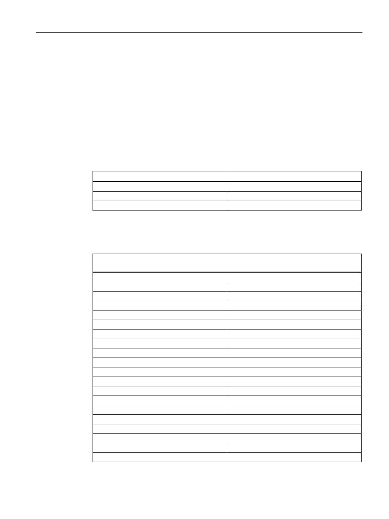
Motion Control version for your project as shown in the table below:
CPU version
Allowed motion control versions
V4.1 (motion control V5.0)
V5.0 or V4.0 or V3.0
V4.0 (motion control V4.0)
V4.0 or V3.0
V3.0 (motion control V3.0)
V3.0
The TO structure is different between motion control versions V3.0 and V5.0. All associated
blocks change as well. Block interfaces, watch tables, and traces update to the new motion
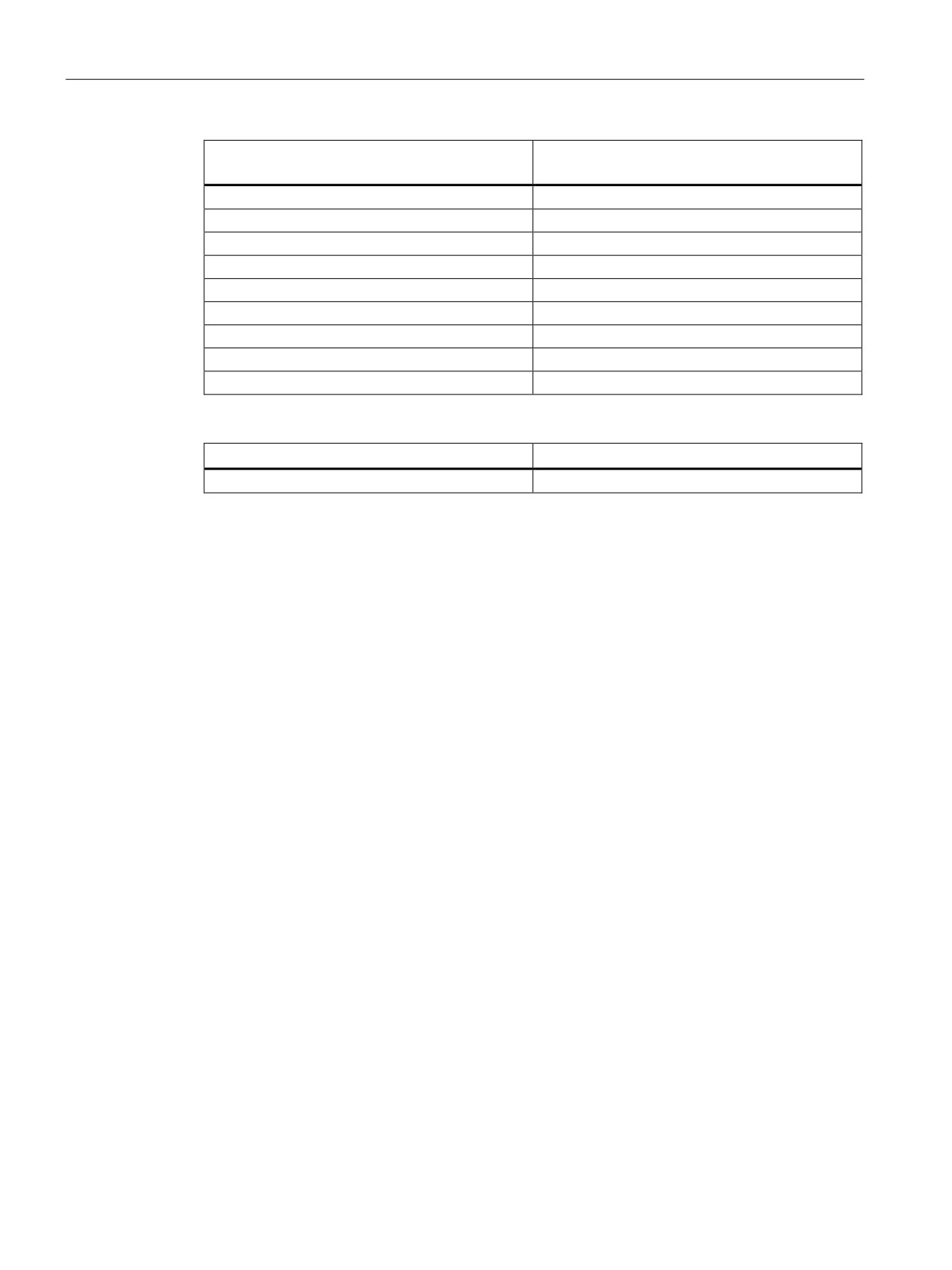
control V5.0 structure. You can find the differences between the V3.0 CPU and V4.1 CPU
motion control axis parameters in the following two tables:
V3.0 CPU
V4.1 CPU
(Motion control V3.0)
(Motion control V5.0)
Config.General.LengthUnit
Units.LengthUnit
Config.Mechanics.PulsesPerDriveRevolution
Actor.DriveParameter.PulsesPerDriveRevolution
Config.Mechanics.LeadScrew
Mechanics.LeadScrew
Config.Mechanics.InverseDirection
Actor.InverseDirection
Config.DynamicLimits.MinVelocity
DynamicLimits.MinVelocity
Config.DynamicLimits.MaxVelocity
DynamicLimits.MaxVelocity
Config.DynamicDefaults.Acceleration
DynamicDefaults.Acceleration
Config.DynamicDefaults.Deceleration
DynamicDefaults.Deceleration
Config.DynamicDefaults.EmergencyDeceleration
DynamicDefaults.EmergencyDeceleration
Config.DynamicDefaults.Jerk
DynamicDefaults.Jerk
Config.PositionLimits_SW.Active
PositionLimitsSW.Active
Config.PositionLimits_SW.MinPosition
PositionLimitsSW.MinPosition
Config.PositionLimits_SW.MaxPosition
PositionLimitsSW.MaxPosition
Config.PositionLimits_HW.Active
PositionLimitsHW.Active
Config.PositionLimits_HW.MinSwitchedLevel
PositionLimitsHW.MinSwitchLevel
Config.PositionLimits_HW.MaxSwitchedLevel
PositionLimitsHW.MaxSwitchLevel
Config.Homing.AutoReversal
Homing.AutoReversal
Config.Homing.Direction
Homing.ApproachDirection
Config.Homing.SideActiveHoming
Sensor[1].ActiveHoming.SideInput
Config.Homing.SidePassiveHoming
Sensor[1].PassiveHoming.SideInput
435
Exchanging a V3.0 CPU for a V4.1 CPU
B.1 Exchanging a V3.0 CPU for a V4.1 CPU
V3.0 CPU
V4.1 CPU
(Motion control V3.0)
(Motion control V5.0)
Config.Homing.Offset
Sensor[1].ActiveHoming.HomePositionOffset
Config.Homing.FastVelocity
Homing.ApproachVelocity
Config.Homing.SlowVelocity
Homing.ReferencingVelocity
MotionStatus.Position
Position
MotionStatus.Velocity
Velocity
MotionStatus.Distance
StatusPositioning.Distance
MotionStatus.TargetPosition
StatusPositioning.TargetPosition
StatusBits.SpeedCommand
StatusBits.VelocityCommand
StatusBits.Homing
StatusBits.HomingCommand
The only "commandtable" parameter that is renamed is the array with the commands:
V3.0
V4.1
Config.Command[]
Command[]
Note: The array "Command[]" is a UDT of the type "TO_CmdTab_Config_Command" in V3.0 and
"TO_Struct_Command" in V4.1.
Instruction changes
The following instructions have changes in parameters or behavior:
● RDREC and WRREC (Page 146)
● CONV (Page 109)
HMI panel communication
If you had one or more HMI panels (Page 20) connected to your S7-1200 V3.0 CPU, the
communication to the S7-1200 V4.1 CPU depends on the type of communication you use
and the firmware version of the HMI panel. Recompile and download your project to the CPU
and the HMI and/or update your HMI firmware.
436
Exchanging a V3.0 CPU for a V4.1 CPU
B.1 Exchanging a V3.0 CPU for a V4.1 CPU
Requirement to recompile program blocks
After exchanging a V3.0 CPU for a V4.1 CPU, you must recompile all program blocks before
you can download them to the V4.1 CPU. Additionally, if any of the blocks have know-how
protection (Page 89) or copy protection bound to a PLC serial number (Page 90), you must
remove the protection before you compile and download the blocks. (You do not, however,
need to deactivate copy protection bound to a memory card.) After a successful compile, you
can reconfigure the know-how protection and/or PLC serial number copy protection. Note
that if your project includes any blocks with know-how protection that an OEM (Original
Equipment Manufacturer) provided, you must contact the OEM to provide V4.1 versions of
those blocks.
In general, Siemens recommends that you recompile the hardware configuration and
software in STEP 7 and download to all devices in your project after the device exchange.
Correct any errors that compiling the project finds, and recompile until you have no errors.
Then, you can download the project to the V4.1 CPU.
S7-1200 V3.0 projects might not fit in S7-1200 V4.1 CPUs
S7-1200 V4.0 added a reserve area of 100 bytes to each DB to support download without
reinitialization.
You can remove the 100-byte reserve area from DBs prior to attempting to download a V3.0
project to a V4.1CPU.
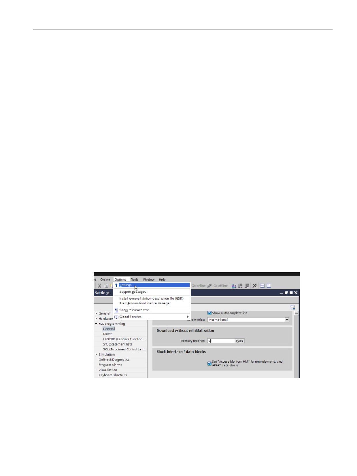
To remove the 100-byte reserve area, follow these steps before you perform the device
exchange:
1. From the TIA Portal main menu, select the Options > Settings menu command.
2. From the navigation tree, open the PLC programming > General node.
3. In the "Download without reinitialization" area, set the memory reserve to 0 bytes.
437
Exchanging a V3.0 CPU for a V4.1 CPU
B.1 Exchanging a V3.0 CPU for a V4.1 CPU
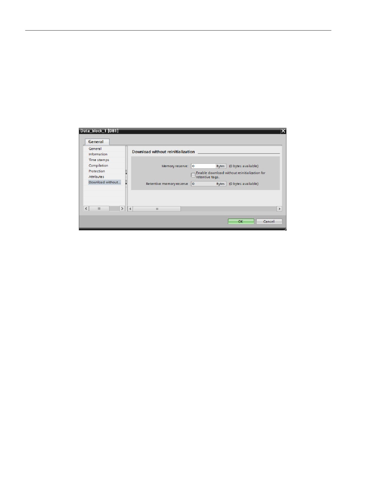
If you have already performed the device exchange, you must remove the 100-byte reserve
from each block individually:
1. From the project tree, right-click a data block from the Program blocks folder and select
Properties from the shortcut menu.
2. In the Data block properties dialog, select the "Download without reinitialization" node.
3. Set the memory reserve to 0 bytes.
4. Repeat for each data block in your project.
Refer to the S7-1200 Programmable Controller System Manual for complete details on the
V4.1 features.
438
Index
FM, 362
Korea Certification, 363
A
Maritime, 364
AS-i
Access protection, CPU, 87
add AS-i master CM1243-2 module, 164
Active/passive communication
add AS-i slave, 164
configuring the partners, 154, 170
address, 166
connection IDs, 148
AS-i master CM 1243-2, 163
parameters, 152
AT tag overlay, 68
Active/Passive connection, 154
ATEX approval, 363
Ad hoc mode, TCP and ISO on TCP, 148
Add new device
detect existing hardware, 75
B
unspecific CPU, 75, 350
Adding inputs or outputs to LAD or FBD
Basic panels (HMI), 20
instructions, 31
Battery board, BB 1297, 394
Addressing
Binding to a CPU, memory card, or password, 90
Boolean or bit values, 65
Bit logic, 106
data block, 64
Block call
global memory, 64
Basics, 56
individual inputs (I) or outputs (Q), 65
Block move (MOVE_BLK) instruction, 108
memory areas, 64
Blocks
process image, 64
calling another code block, 101
temp memory, 64
consistency check, 126
Air flow, 24
copying blocks from an online CPU, 344
Analog I/O
counters (quantity and memory requirements), 17
conversion to engineering units, 47
data blocks (DBs), 56
input representation (current), 397
events, 58
input representation (voltage), 396
function blocks (FBs), 56
output representation (current), 400
functions (FCs), 56
output representation (voltage), 400
getting started, 99
step response times for inputs, 398
interrupts, 17, 58
Analog inputs
monitoring, 17
specifications for CPUs, SBs, and SMs, 395
nesting depth, 17
specifications for RTD/TC SBs and SMs, 408
number of code blocks, 17
Analog signal boards
number of OBs, 17, 58
SB 1231, 390
organization blocks (OBs), 17, 56, 57, 58
SB 1232, 390
password protection, 89
Analog signal modules
size of the user program, 17
SM 1231, 391
start-up OBs, 58
SM 1231 RTD, 405
timers (quantity and memory requirements), 17
SM 1231 Thermocouple, 407
types, 56
SM 1232, 391
Boolean or bit values, 65
SM 1234, 392
Box instruction
Approvals
Getting started, 45
ATEX, 363
Bus connector, 19
CE, 361
C-Tick, 363
cULus, 362
439
Index
C
overview, 19
RS485, 184
CALCULATE (calculate), 111
Communication interfaces
scaling analogs, 47
add modules, 78
using for complex equations, 46
CB 1241 RS485, 424
Call structure, 126
CM 1241 RS232, 426
CANopen modules
comparison chart of the modules, 18
021620-B, 021630-B, 432
RS232 and RS485, 184
Capturing values from an online DB, 343
Communication module (CM)
CB 1241 RS485, 424
add AS-i master CM1243-2 module, 164
CE approval, 361
add CM 1243-5 (DP master) module, 160
CEIL (ceiling), 110
add modules, 78
Change device, 77
adding a new device, 76
Changing settings for STEP 7, 32
CM 1241 RS232, 426
Clearance, airflow and cooling, 24
CM 1241 RS422/RS485, 425
Clock memory byte, 83
comparison chart, 18
Code block, 93
device configuration, 73
binding to a CPU, memory card, or password, 90
LED indicators, 184
calling a block, 101
overview, 19
copy protection, 90
RS232 and RS485, 184
counters (quantity and memory requirements), 17
Communication module (CM), USS library, 186
DB (data block), 98
Communication processor (CP)
FB (function block), 97
add modules, 78
FC (function), 97
comparison chart, 18
interrupts, 17
overview, 19
know-how protection, 89
Compact switch module, CSM 1277, 431
monitoring, 17
Compare instructions, 108
nesting depth, 17
Comparing and synchronizing online/offline CPUs, 345
number of code blocks, 17
Comparison chart
number of OBs, 17
CPU models, 16
organization blocks (OBs), 17, 95
HMI devices, 20
size of the user program, 17
modules, 18
timers (quantity and memory requirements), 17
Configuration
Columns and headers in task cards, 33
add modules, 78
Communication
AS-i, 165
active/passive, 152, 154, 170
discover, 75, 350
AS-i address, 166
HSC (high-speed counter), 138
configuration, 152, 154, 170
Industrial Ethernet port, 85
connection IDs, 148
IP address, 85
IP address, 85
network connection, 140
network, 139
PID_Compact and PID_3Step instructions, 222
network connection, 140
PID_Temp instructions, 225
number of connections
PROFIBUS, 161
(PROFINET/PROFIBUS), 144
PROFIBUS address, 161
parameters, 152
PROFINET, 85
PROFIBUS address, 161
Startup parameters, 80
PROFINET and PROFIBUS, 141
user-defined Web pages, 260
TCON_Param, 152
Configuration control (option handling), 79
Communication board (CB)
Configuring parameters
add modules, 78
CPU, 80, 84
CB 1241 RS485, 424
Ethernet port, 85
comparison chart, 18
LED indicators, 184
440
Index
modules, 80, 84
CPU 1215C, 371
PROFINET, 85
CPU 1217C, 371
Connections
device configuration, 73
configuration, 152
diagnostics buffer, 346
connection IDs, 148
Ethernet port, 85
Ethernet protocols, 169
force, 340, 341
HMI connection, 49
going online, 335
network connection, 49
HSC configuration, 138
number of connections
IP address, 85
(PROFINET/PROFIBUS), 144
know-how protection, 89
partners, 154, 170
monitoring online, 337
S7 connection, 169
network connection, 140
types of communication, 141
number of communication connections, 144
types, multi-node connections, 169
online, 346
Web server, 256
Operating modes, 55
Consistency check, 126
operator panel, 32, 55, 336
Constraints
overview, 15
user-defined Web pages, 259
password protection, 87
Web server, 256
processing the OBs, 95
Contact information, 5, 77
PROFIBUS address, 161
Contacts
PROFINET, 85
programming, 42
Program execution, 53
Control DB for user-defined Web pages
reset to factory settings, 347
parameter to WWW instruction, 260
resetting the start values of a DB, 343
CONV (convert), 109
RUN/STOP buttons, 32
Cooling, 24
Security levels, 87, 87
Copy protection
signal boards (SB), 19
binding to a CPU, memory card, or password, 90
Startup parameters, 80
Copying blocks from an online CPU, 344
Startup processing, 80
Counter instructions, 118
step response times for analog inputs, 398
Counters
thermal zone, 22, 24
HSC (high-speed counter), 129
types of communication, 141
HSC configuration, 138
unspecific CPU, 75, 350
HSC operation, 131
watch tables, 338
quantity, 17
CPU properties, user-defined Web pages, 260
size, 17
Creating a network connection
CPU
between PLC and HMI, 49
access protection, 87
between PLCs, 140
add modules, 78
Creating an HMI connection, 49
adding a new device, 76
Creating user-defined Web page DBs, 260
AS-i address, 166
Creating user-defined Web pages, 257
calling a block, 101
Cross-reference to show usage, 125
capturing values of a DB, 343
CSM 1277 compact switch module, 431
communication boards (CB), 19
C-Tick approval, 363
comparing and synchronizing blocks, 345
CTRL_PWM instruction, 121
comparison chart, 16
cULus approval, 362
configuring communication to HMI, 139
Customer support, 5
Configuring parameters, 80, 84
Cycle time monitoring, 336
copying blocks from an online CPU, 344
CPU 1211C, 371
CPU 1212C, 371
CPU 1214C, 371
441
Index
D
Digital outputs
Specifications for Relay, 24 VDC CPUs, SMs, and
Data block
SBs, 387
capturing values, 343, 343
Digital signal boards
global data block, 64, 98
SB 1221, 375
instance data block, 64
SB 1222, 375
organization blocks (OBs), 95
SB 1223, 375
resetting the start values, 343, 343
Digital signal modules
Data handling block (DHB), 98
SM 1221, 378
Data log
SM 1222, 380
data log overview, 122
SM 1223, 382, 383
Data types, 62
Discover, 350
DTL, 62
Discover to upload an online CPU, 75
Date and Time Long data type, 62
Documentation, 4
DB (data block), 98
Download in RUN mode
DC
initiating from STEP 7, 352
outputs, 368
overview, 351
Debugging n RUN mode, 351
Drag and drop between editors, 34
Degree of protection, 367
DTL data type, 62
Designing a PLC system, 56, 93
Dynamic binding, 90
Device configuration, 73
add modules, 78
adding a new device, 76
E
AS-i, 165
AS-i port, 165
Edit in RUN mode, (Download in RUN mode)
changing a device type, 77
Electromagnetic compatibility, 366
Configuring the CPU, 80, 84
Electromagnetic compatibility (EMC), 365
Configuring the modules, 80, 84
Environmental
discover, 75, 350
operating conditions, 366
Ethernet port, 85
transport and storage conditions, 366
network connection, 140
Ethernet
PROFIBUS, 161
ad hoc mode, 148
PROFINET, 85
communication, 139
unplugged modules, 37
connection IDs, 148
Device exchange
CSM 1277 compact switch module, 431
procedure, 77
GET, 168
V3.0 CPU for a V4.1 CPU, 433
IP address, 85
DeviceStates, 128
network connection, 140
Diagnostics
number of communication connections, 144
buffer, 346
overview, 147
DeviceStates, 128
PUT, 168
GET_DIAG, 128
types of communication, 141
Get_IM_Data, 128
Ethernet instructions
LED instruction, 127
TRCV_C, 146
ModuleStates, 128
TSEND_C, 146
status indicator, 83
Ethernet protocols, 147
Differences
multi-node connections, 169
in point-to-point instructions, 183
Event execution, 58
Digital inputs
Events, 346
AC specifications for SMs, 386
Examples, communication
VDC specifications for CPUs, SMs, and SBs, 384
AS-i slave addressing, 166
CPU communication over TSEND_C or TRCV_C
connections, 151
442
Index
CPU communication with a common send and
Fragment DBs (user-defined Web pages)
receive connection, 150
generating, 260
CPU communication with separate send and
Freeport protocol, 182
receive connections, 149
Frequency, clock bits, 83
PROFINET communication protocols, 147
Function (FC), 97
telecontrol, 177
know-how protection, 89
Examples, instructions
Function block (FB)
CALCULATE, 46
Initial value, 97
Examples, motion control
Instance data block, 97
configuring a technology object motion command
know-how protection, 89
table, 293
Output parameters, 97
CPU 1211C, CPU 1212C, CPU 1214C, and CPU
1215C pulse output speed configurations, 267
CPU 1217C pulse output speed configuration, 266
G
velocity characteristics of MC homing, 306
Generating user-defined Web page DBs, 260
Examples, PID
GET, 168
PID_3Step, configuration settings, 223
GET (read data from a remote CPU)
PID_Compact, configuration settings, 222
configuring the connection, 155
PID_Temp, configuration settings, 225
Get LED status, 127
Examples, various
GET_DIAG, 128
AT tag overlay, 68
Get_IM_Data, 128
dragging and dropping between editors, 34
Getting started
slice of tagged data type, 68
addressing, 44
trace and logic analyzer function, 353
box instruction, 45
Exchanging a V3.0 CPU for a V4.1 CPU, 433
code block, 99
Expandable instructions, 31
contacts, 42
Expanding the capabilities of the S7-1200, 18
CPU, 39
HMI, 48, 50
HMI connection, 49
F
instructions, 44
Factory settings reset, 347
LAD program, 42, 45
FAQs, 4
Math instruction, 45
Favorites toolbar, 30
network connection, 49
FB (function block), 97
new PLC, 39
FBD (function block diagram), 103
PLC tags, 40, 44
FC (function), 97
program block, 99
Features, new, 26
Project, 39
Firmware update
split editors, 40, 44, 44
from STEP 7, 348
tags, 40, 44
First scan indicator, 83
Global data block, 64, 98
FLOOR, 110
Global library
FM approval, 362
USS, 186
Force, 340
Global memory, 64
I memory, 340, 341
Guidelines
inputs and outputs, 341
installation, 23
peripheral inputs, 340, 341
scan cycle, 341
Force table
addressing peripheral inputs, 340
force, 340
force operation, 341
443
Index
H
analog input representation (current), 397
analog input representation (voltage), 396
Hardware configuration, 73
analog output representation (current), 400
add modules, 78
analog output representation (voltage), 400
adding a new device, 76
force operation, 341
AS-i, 165
monitoring status in LAD, 338
AS-i port, 165
step response times for analog inputs, 398
Configuring the CPU, 80, 84
watch tables, 338
Configuring the modules, 80, 84
Industrial environments
discover, 75, 350
approvals, 364
Ethernet port, 85
Information resources, 4
network connection, 140
Initial values
PROFIBUS, 161
capturing and resetting the start values of a DB, 343
PROFINET, 85
Inputs and outputs
High potential isolation test, 367
monitoring, 337
High-speed counter
Inserting a device
cannot be forced, 341
unspecific CPU, 75, 350
configuration, 138
Inserting instructions
HSC, 129
drag and drop, 30
operation, 131
drag and drop between editors, 34
HMI
favorites, 30
configuring PROFINET communication, 139
Installation
Getting started, 48, 50
air flow, 24
HMI connection, 49
clearance, 24
network connection, 49
cooling, 24
screen, 50
guidelines, 23
HMI devices
mounting dimensions, 22
network connection, 140
overview, 23
overview, 20
signal modules (SM), 19
Hotline, 5
thermal zone, 22, 24
HSC (high-speed counter)
Instance data block, 64
configuration, 138, 138
Instructions
operation, 129, 131
adding a parameter, 45
HSC clock input rates, 386
adding inputs or outputs to LAD or FBD
HTML pages, user-defined, 257
instructions, 31
developing, 257
bit logic, 106
page locations, 260
block move (MOVE_BLK), 108
refreshing, 258
CALCULATE, 46
HTTP connections, Web server, 256
CALCULATE (calculate), 111
CEIL (ceiling), 110
columns and headers, 33
I
compare, 108
I memory
CONV (convert), 109
force, 340
counter, 118
force operation, 341, 341
CTRL_PWM), 121
force table, 340
DeviceStates, 128
monitor, 337
drag and drop, 30
monitor LAD, 338
drag and drop between editors, 34
peripheral input addresses (force table), 340
expandable instructions, 31
watch table, 337
favorites, 30
I/O
FLOOR, 110
addressing, 66
force operation, 341
444
Index
GET, 168
power-up, 355
GET_DIAG, 128
technology overview, 355
Get_IM_Data, 128
IO-Link Master
Getting started, 44, 45
block diagram, 358
HSC (high-speed counter), 129, 131
connection examples, 359
inserting, 30
illustration, 357
LED status, 127
IO-Link Master signal module, 428
MC_ChangeDynamic (change dynamic settings for
IP address, 85, 85
the axis), 328
configuring the online CPU, 346
MC_CommandTable, 326
IP router, 85
MC_Halt (pause axis), 315
ISO on TCP
MC_Home (home axis), 312
ad hoc mode, 148
MC_MoveAbsolute (position axis absolutely), 317
ISO on TCP protocol, 147
MC_MoveJog (move axis in jog mode), 324
ISO-on-TCP
MC_MoveRelative (position axis relatively), 319
connection configuration, 154
MC_MoveVelocity (move axis at predefined
connection IDs, 148
velocity), 321
parameters, 152
MC_Power (release/block axis), 308
MC_ReadParam (read parameters of a technology
object), 332
K
MC_Reset (confirm error), 311
Know-how protection
MC_WriteParam (write to parameters of a
password protection, 89
technology object), 330
Korea Certification approval, 363
ModuleStates, 128
monitor, 338
monitoring status or value, 337
L
motion control, 307
move, 108
LAD (ladder logic)
NORM_X (normalize), 111
monitor, 338
PID_Compact (universal PID controller with
monitoring status or value, 337
integrated tuning), 195
overview, 102
PID_Temp (universal PID controller that allows
program editor, 338
handling of temperature control), 210
status, 338, 340
PUT, 168
Latency, 58
ROUND, 110
LED (Get LED status), 127
SCALE_X (scale), 111
LED indicators
scaling analog values, 47
communication interface, 184
status, 338
LED instruction, 127
TRCV_C, 146
Linear programming, 93
TRUNC (truncate), 110
Load memory, 16, 61
TSEND_C, 146
user-defined Web pages, 259
uninterruptible move (UMOVE_BLK), 108
Local/Partner connection, 154
versions of instructions, 33
Logic analyzer, 353
WWW, 260
Interrupts
interrupt latency, 58
overview, 57
IO-Link
components, 355
configuring, 356
data, 356
device profile, 356
445
Index
M
signal modules (SM), 19
thermal zone, 22, 24
MAC address, 85
ModuleStates, 128
Main entry, 380
Monitoring
Manuals, 4
capturing values of a DB, 343
Maritime approval, 364
force operation, 341
Math, 46, 111
force table, 340
Maximum Web server connections, 256
LAD status, 338
MC_ChangeDynamic (change dynamic settings for the
LAD status and use of watch table, 337
axis), 328
LED instruction, 127
MC_CommandTable, 326
resetting the start values of a DB, 343
MC_Halt (pause axis), 315
Monitoring the program, 124
MC_Home (home axis), 312
Motion control
MC_MoveAbsolute (position axis absolutely), 317
configuring the axis, 271, 280
MC_MoveJog (move axis in jog mode), 324
hardware and software limit switches, 298
MC_MoveRelative (position axis relatively), 319
homing (sequence for active homing), 306
MC_MoveVelocity (move axis at predefined
homing configuration parameters, 303
velocity), 321
homing the axis, 302
MC_Power (release/block axis), 308
MC_ChangeDynamic (change dynamic settings for
MC_ReadParam (read parameters of a technology
the axis), 328
object), 332
MC_CommandTable, 326
MC_Reset (confirm error), 311
MC_Halt (pause axis), 315
MC_WriteParam (write to parameters of a technology
MC_Home (home axis), 312
object), 330
MC_MoveAbsolute (position axis absolutely), 317
Memory
MC_MoveJog (move axis in jog mode), 324
clock memory, 82
MC_MoveRelative (position axis relatively), 319
load memory, 61
MC_MoveVelocity (move axis at predefined
peripheral input addresses (force table), 340
velocity), 321
retentive memory, 61
MC_Power (release/block axis), 308
system memory, 82
MC_ReadParam (read parameters of a technology
Temp memory (L), 64
object), 332
work memory, 61
MC_Reset (confirm error), 311
Memory areas
MC_WriteParam (write to parameters of a
addressing Boolean or bit values, 65
technology object), 330
data block, 64
overview, 263
global memory, 64
phasing, 268
immediate access, 64
Motion control instructions, 307
process image, 64
Mounting
temp memory, 64
airflow, 24
Memory card
clearance, 24
load memory, 61
cooling, 24
Memory usage monitoring, online, 336
dimensions, 22
Modbus
guidelines, 23
versions, 33
thermal zone, 22, 24
Modifying
Move instruction, 108
program editor status, 338
Movement sequence (MC_CommandTable), 326
Modules
MRES, operator panel, 32, 55, 336
communication boards (CB), 19
Multi-node connections
communication module (CM), 19
connection types, 169
communication processor (CP), 19
Ethernet protocols, 169
comparison chart, 18
My Documentation Manager, 4
Configuring parameters, 80, 84
signal board (SB), 19
446
Index
N
priority classes, 57
processing, 95, 95
Network
Output parameters, 97
network connection, 49
Network communication, 139
Network connection
P
connecting devices, 140
HMI devices, 49
Panels (HMI), 20
Network, LAD programming, 42
Parameter assignment, 97
New features, 26
Passive/active communication
New project
configuring the partners, 154, 170
adding an HMI device, 48
connection IDs, 148
getting started, 39
parameters, 152
HMI connection, 49
Password protection
HMI screen, 50
access to the CPU, 87
network connection, 49
binding to a CPU, memory card, or password, 90
NORM_X (normalize), 111
code block, 89
copy protection, 90
CPU, 87
O
Phasing, 268
PID
OB, (Organization block)
commisioning, 239
Online
overview, 192
capturing values of a DB, 343
PID_3STEP (PID controller with tuning for
comparing and synchronizing, 345
valves), 201
cycle time monitoring, 336
PID_3Step algorithm, 192
discover, 350
PID_Compact (universal PID controller with
force, 340
integrated tuning), 195
force operation, 341
PID_Compact algorithm, 192
going online, 335
PID_Temp (universal PID controller that allows
IP address, 346
handling of temperature control), 210
memory usage monitoring, 336
PLC
monitoring status or value, 337
add modules, 78
operator panel, 32, 55, 336
calling a block, 101
resetting the start values of a DB, 343
comparing and synchronizing, 345
RUN/STOP buttons, 32
copying blocks from an online CPU, 344
status, 338
force, 340
time of day, 346
force operation, 341
watch table, 337, 338
Getting started, 39
Online and diagnostic tools
HSC configuration, 138
downloading in RUN mode, 351
instructions, 44
OPC, configuration, 178
know-how protection, 89
Operating mode, 32, 32, 55, 336
monitoring, 337
Operator panel, 32, 55, 336
overview of the CPU, 15
Operator panels, 20
tags, 40, 44
Option handling (configuration control), 79
using blocks, 56, 93
Organization block
PLC tags
call, 57
Getting started, 40, 44
configuring operation, 96
PM 1207 power module, 431
creating, 96
Podcasts, 4
function, 57
Point-to-Point communication, 182
know-how protection, 89
Port numbers
multiple cyclic, 96
assigning to communication partners, 147
447
Index
Portal view, 29
Getting started, 45
adding a new device, 76
Math instruction, 45
Configuring the CPU, 80, 84
organization blocks (OBs), 95
Configuring the Ethernet port, 85
password protection, 89
Configuring the modules, 80, 84
priority class, 57
PROFINET, 85
resetting the start values of a DB, 343
Power supply module
sample network, 42, 45
PM1207, 431
Program block
Priority
creating, 99
priority class, 57
getting started, 39
priority in processing, 58
Program card, 61
Process image
Program editor
force, 340
capturing values of a DB, 343
force operation, 341
monitor, 338
monitor, 338
resetting the start values of a DB, 343
monitoring status or value, 337
status, 338
status, 338, 340
Program execution
PROFIBUS
block structure, 56
add CM 1243-5 (DP master) module, 160
overview, 53
add DP slave, 160
Program information
address, 161
In the call structure, 126
address, configuring, 161
Program structure, 93
CM 1242-5 (DP slave) module, 157
Programming
CM 1243-5 (DP master) module, 157
adding inputs or outputs to LAD or FBD
GET, 168
instructions, 31
master, 157
binding to a CPU, memory card, or password, 90
network connection, 140
comparing and synchronizing code blocks, 345
number of communication connections, 144
drag and drop between editors, 34
PUT, 168
expandable instructions, 31
S7 connection, 169
favorites, 30
slave, 157
FBD (function block diagram), 103
PROFINET, 139
Getting started, 44
ad hoc mode, 148
inserting instructions, 30
connection IDs, 148
LAD (ladder), 102
GET, 168
Linear, 93
IP address, 85
PID overview, 192
network connection, 140
PID_3STEP (PID controller with tuning for
number of communication connections, 144
valves), 201
overview, 147
PID_3Step algorithm, 192
PUT, 168
PID_Compact (universal PID controller with
S7 connection, 169
integrated tuning), 195
testing a network, 86
PID_Compact algorithm, 192
types of communication, 141
PID_Temp (universal PID controller that allows
PROFINET interface
handling of temperature control), 210
Ethernet address properties, 85
priority class, 57
PROFINET RT, 147
SCL (Structured Control Language), 103, 104
Program
Structured, 93
binding to a CPU, memory card, or password, 90
unplugged modules, 37
calling a block, 101
unspecific CPU, 75, 350
capturing values of a DB, 343
Project
copying blocks from an online CPU, 344
access protection, 87
getting started, 42
adding an HMI device, 48
448
Index
binding to a CPU, memory card, or password, 90
Relay electrical service life, 369
comparing and synchronizing, 345
Replacing modules, 37
getting started, 39
Reset to factory settings, 347
HMI connection, 49
Resetting the start values of a DB, 343
HMI screen, 50
Retentive memory, 16, 61
network connection, 49
Reverse voltage protection, 368
program, 44
ROUND, 110
protecting a code block, 89
Router IP address, 85
restricting access to a CPU, 87
RS232 and RS485 communication modules, 184
tags, 40, 44
RTD modules overview, 402
Project view, 29, 29
Run axis commands as movement sequence
adding a new device, 76
(MC_CommandTable), 326
Configuring the CPU parameters, 80, 84
RUN mode, 55, 56
Configuring the Ethernet port, 85
force operation, 341
Configuring the modules, 80, 84
operator panel, 32, 55, 336
device configuration, 73
Program execution, 53
PROFINET, 85
toolbar buttons, 32
Protection class, 367
RUN/STOP buttons, 32
Protection level
binding to a CPU, memory card, or password, 90
code block, 89
S
CPU, 87
S7 communication
Protocol
configuring the connection, 155
communication, 182
SCALE_X (scale), 111
freeport, 182
Scaling analogs, 47
ISO on TCP, 147
Scan cycle
Modbus, 182
force operation, 341, 341
PROFINET RT, 147
SCL (Structured Control Language)
TCP, 147
CEIL (ceiling), 110
UDP, 147
CONV (convert), 109
USS, 182
DeviceStates, 128
PTO (pulse train output), 121
FLOOR, 110
cannot be forced, 341
GET_DIAG, 128
PtP communication, 182
Get_IM_Data, 128
Pulse train output (PTO), 121
LED status, 127
PUT, 168
MC_ChangeDynamic (change dynamic settings for
PUT (write data to a remote CPU)
the axis), 328
configuring the connection, 155
MC_CommandTable, 326
PWM
MC_Halt (pause axis), 315
CTRL_PWM instruction, 121
MC_Home (home axis), 312
PWM (pulse width modulation)
MC_MoveAbsolute (position axis absolutely), 317
cannot be forced, 341
MC_MoveJog (move axis in jog mode), 324
MC_MoveRelative (position axis relatively), 319
MC_MoveVelocity (move axis at predefined
Q
velocity), 321
Queuing, 58
MC_Power (release/block axis), 308
MC_ReadParam (read parameters of a technology
object), 332
R
MC_Reset (confirm error), 311
MC_WriteParam (write to parameters of a
Rated voltages, 367, 367
technology object), 330
Refreshing user-defined Web pages, 258
ModuleStates, 128
449
Index
NORM_X (normalize), 111
Signal module (SM)
overview, 103
step response times for analog inputs, 398
PID overview, 192
Signal modules (SM)
PID_3STEP (PID controller with tuning for
add modules, 78
valves), 201
adding a new device, 76
PID_3Step algorithm, 192
analog input representation (current), 397
PID_Compact (universal PID controller with
analog input representation (voltage), 396
integrated tuning), 195
analog output representation (current), 400
PID_Compact algorithm, 192
analog output representation (voltage), 400
PID_Temp (universal PID controller that allows
device configuration, 73
handling of temperature control), 210
overview, 19
program editor, 104
SM 1221 DI 16 24 VDC, 378
round, 110
SM 1221 DI 8 24 VDC, 378
SCALE_X (scale), 111
SM 1222 DQ 16 24 VDC, 380
truncate, 110
SM 1222 DQ 16 Relay, 380
Var section, 104
SM 1222 DQ 8 24 VDC, 380
Security
SM 1222 DQ 8 Relay, 380
access protection, 87
SM 1222 DQ 8 Relay Changeover, 380
binding to a CPU, memory card, or password, 90
SM 1223 DI 1223 DI 120/230 VAC/DQ Relay, 383
copy protection, 90
SM 1223 DI 16/DQ 16 Relay, 382
CPU, 87
SM 1223 DI 8/ DQ 8/DQ Relay, 382
know-how protectionf for a code block, 89
SM 1223 DI 8/DQ 8, 382, 382
Send parameters configuration, 154, 170
SM 1231 AI 4 x 13 bit, 391
Serial communication, 182
SM 1231 AI 4 x 16 bit, 391
Service and support, 5
SM 1231 AI 4 x 16 bit TC, 407
Settings, 32
SM 1231 AI 4 x RTD x 16 bit, 405
Siemens technical support, 5
SM 1231 AI 8 x 13 bit, 391
Signal board (SB)
SM 1231 AI 8 x 16 bit TC, 407
step response times for analog inputs, 398
SM 1231 AI 8 x RTD x 16 bit, 405
Signal boards (SB)
SM 1232 AQ 2 x 14 bit, 391
add modules, 78
SM 1232 AQ 4 x 14 bit, 391
analog output representation (current), 400
SM 1234 AI 4 x 13 bit/AQ 2 x 14 bit, 392
analog output representation (voltage), 400
SM 1278 4xIO-Link Master, 428
device configuration, 73
Slice (of a tagged data type), 67
input representation (current), 397
SM and SB
input representation (voltage), 396
comparison chart, 18
overview, 19
SMS, 177
SB 1221 4 DI 24 VDC 200 kHz, 375
Specifications
SB 1221 4 DI 5 VDC 200 kHz, 375
analog input representation (current), 397
SB 1222 4 DQ 24 VDC 200 kHz, 375
analog input representation (voltage), 396
SB 1222 4 DQ 5 VDC 200 kHz, 375
analog output representation (current), 400
SB 1223 2 DI/2 DQ 24 VDC, 375
analog output representation (voltage), 400
SB 1223 DI/DQ 24 VDC 200 kHz, 375
approvals, 361
SB 1223 DI/DQ 5 VDC 200 kHz, 375
CB 1241 RS485, 424
SB 1231 AI 1 x 12 bit, 390
CM 1241 RS232, 426
SB 1231 AI 1 x 16 bit RTD, 403
CM 1241 RS422/485, 425
SB 1231 AI 1 x 16 bit TC, 403
CPU 1211C, 371
SB 1231 RTD, 403
CPU 1212C, 371
SB 1231 TC, 403
CPU 1214C, 371
SB 1232 AQ 1 x 12 bit, 390
CPU 1215C, 371
Signal boards (SM)
CPU 1217C, 371
adding a new device, 76
electromagnetic compatibility (EMC), 365
450
Index
environmental conditions, 366
adding inputs or outputs to a LAD or FBD
general technical specifications, 361
instruction, 31
industrial environments, 364
AS-i, 165
rated voltages, 367
capturing values of a DB, 343
SB 1221 4 DI 24 VDC 200 kHz, 375
changing the settings, 32
SB 1221 4 DI 5 VDC 200 kHz, 375
comparing and synchronizing, 345
SB 1222 4 DQ 24 VDC 200 kHz, 375
Configuring the CPU, 80, 84
SB 1222 4 DQ 5 VDC 200 kHz, 375
Configuring the modules, 80, 84
SB 1223 2 DI/2 DQ 24 VDC, 375
copying blocks from an online CPU, 344
SB 1223 DI/DQ 24 VDC 200 kHz, 375
device configuration, 73
SB 1223 DI/DQ 5 VDC 200 kHz, 375
diagnostics buffer, 346
SB 1231 AI 1 x 12 bit, 390
drag and drop between editors, 34
SB 1231 AI 1 x 16 bit RTD, 403
Ethernet port, 85
SB 1231 AI 1 x 16 bit TC, 403
expandable inputs or outputs, 31
SB 1232 AQ 1 x 12 bit, 390
favorites, 30
SM 1221 DI 16 24 VDC, 378
force, 340
SM 1221 DI 8 24 VDC, 378
force operation, 341
SM 1222 DQ 16 24 VDC, 380
HSC configuration, 138
SM 1222 DQ 16 Relay, 380
inserting instructions, 30
SM 1222 DQ 8 24 VDC, 380
monitoring, 337, 338
SM 1222 DQ 8 Relay, 380
network connection, 140
SM 1222 DQ 8 Relay Changeover, 380
operator panel, 32, 55, 336
SM 1223 DI 120/230 VAC/DQ Relay, 383
password protection, 89
SM 1223 DI 16/DQ 16 Relay, 382
Portal view and Project view, 29
SM 1223 DI 8/DQ 8, 382, 382
priority class (OB), 57
SM 1223 DI 8/DQ 8 Relay, 382
PROFIBUS, 161
SM 1231 AI 4 x 13 bit, 391
PROFINET, 85
SM 1231 AI 4 x 16 bit, 391
resetting the start values of a DB, 343
SM 1231 AI 4 x 16 bit TC, 407
RUN/STOP buttons, 32
SM 1231 AI 4 x RTD x 16 bit, 405
unplugged modules, 37
SM 1231 AI 8 x 13 bit, 391
STEP 7 programming
SM 1231 AI 8 x 16 bit TC, 407
user-defined Web pages, 260
SM 1231 AI 8 x RTD x 16 bit, 405
STEP 7 web pages, 4
SM 1232 AQ 2 x 14 bit, 391
STOP mode, 55
SM 1232 AQ 4 x 14 bit, 391
force operation, 341
SM 1234 AI 4 x 13 bit/AQ 2 x 14 bit, 392
operator panel, 32, 55, 336
SM 1278 4xIO-Link Master, 428
toolbar buttons, 32
step response times for inputs, 398
Structured programming, 93, 93
Split editors
Subnet mask, 85
Getting started, 40, 44, 44
Support, 5
Standard Web pages, 253, 254
Surge immunity, 365
STARTUP mode
System memory byte, 83
force operation, 341
Program execution, 53
Startup parameters, 80
Status
LED indicators (communication interface), 184
LED instruction, 127
STEP 7
add modules, 78
adding a new device, 76
451
Index
T
TRCV_C
ad hoc mode, 148
Tag
connection parameters, 152
force operation, 341
TRCV_C (receive data via Ethernet (TCP))
monitoring status or value, 337
connection IDs, 148
overlay, 68
TRCV_C (receive data via Ethernet (TCP))
slice, 67
configuration, 154
Tags
TRCV_C instruction, 146
Getting started, 40, 44
Triggering
Task cards
trace, 353
columns and headers, 33
TRUNC (truncate), 110
TCON
TS Adapter, 18
configuration, 154
TSAP (transport service access points), 156
connection IDs, 148
instructions for assigning to devices, 147
connection parameters, 152
TSEND
TCON_Param, 152
connection IDs, 148
TCP
TSEND_C
ad hoc mode, 148
connection parameters, 152
connection configuration, 154, 154
TSEND_C (send data via Ethernet (TCP))
connection IDs, 148
configuration, 154
parameters, 152
connection IDs, 148
protocol, 147
TSEND_C instruction, 146
TCP/IP communication, 139, 147
TURCV
Technical specifications, 361
connection parameters, 152
Technical support, 5
TURCV (receive data via Ethernet (UDP))
Technology module, SM 1278 4xIO-Link Master, 428
configuration, 154
Technology objects
TUSEND
Motion control, 270
parameters, 152
PID, 193
TUSEND (send data via Ethernet (UDP))
Telecontrol, 173
configuration, 154
TeleService via GPRS, 173
Temp memory (L), 64
Testing the program, 124
U
Thermal zone, 22, 24
Thermocouple modules overview, 402
UDP
TIA Portal
connection configuration, 154
adding a new device, 76
parameters, 152
Configuring the CPU, 80, 84
UDP protocol, 147
Configuring the modules, 84
Uninterruptible move (UMOVE_BLK) instruction, 108
device configuration, 73
Unplugged modules, 37
PROFINET, 85
Unspecific CPU, 75, 350, 350
TIA Portal, Portal view and Project view, 29
Updating firmware
Time of day
from STEP 7, 348
configuring the online CPU, 346
Updating user-defined Web pages, 258
Timers
Upgrading a V3.0 CPU to V4.1, 433
quantity, 17
Upload
size, 17
discover, 350
Trace feature, 353
Uploading
TRCV
copying blocks from an online CPU, 344
connection IDs, 148
user program, 344
TRCV (receive data via Ethernet (TCP))
User interface
ad hoc mode, 148
STEP 7 project and portal views, 29
452
Index
User program
SM 1222 DQ 16 24 VDC, 381
adding inputs or outputs to LAD or FBD
SM 1222 DQ 16 Relay, 381
instructions, 31
SM 1223 DI 16 VDC / DQ 16 Relay, 382
binding to a CPU, memory card, or password, 90
SM 1223 DI 16 VDC/ DQ 16 24 VDC, 382
copying blocks from an online CPU, 344
SM 1223 DI 8 120/230 VAC/DQ 8 Relay, 383
drag and drop between editors, 34
SM 1231 AI 8 x 13 bit, 392
expandable instructions, 31
SM 1231 RTD 4 x 16 bit, 406
favorites, 30
SM 1231 RTD 8 x 16 bit, 406
inserting instructions, 30
SM 1232 AQ 4 x 13 bit, 392
organization blocks (OBs), 95
SM 1234 AI 4 x 13 bit/AQ 2 x 14 bit, 392
password protection, 89
SM 1278 IO-Link Master, 430
User-defined Web pages, 253, 257
Wiring guidelines
configuring, 260
clearance for airflow and cooling, 24
creating with HTML editor, 257
Work memory, 16, 61
enabling with WWW instruction, 260
WWW, 260
generating program blocks, 260
load memory constraints, 259
programming in STEP 7, 260
refreshing, 258
USS protocol library, 186
V
Valve PID tuning, 201
Versions of instructions, 33
Visualization, HMI devices, 20
W
Watch table
force, 124
monitor, 337
Watch tables, 338
Web pages
STEP 7 service, support, and documentation, 4
Web pages, user-defined, 257
Web server, 253
constraints, 256
maximum HTTP connections, 256
Wiring diagrams
CB 1241 RS 485, 424
CPU 1214C AC/DC/Relay, 374
CPU 1214C DC/DC/DC, 374
SB 1221 DI 4 200 kHz, 377
SB 1223 DI 2/DQ 2 200 kHz, 377
SB 1231 AI 1 x 12 bit, 390
SB 1231 AI 1 x 16 bit RTD, 404
SB 1231 AI 1 x 16 bit TC, 404
SB 1232 AQ 1 x 12 bit, 390
SM 1221 DI 16 24 VDC, 379
SM 1221 DI 8 24 VDC, 379
453