Volvo S60 (2018 year). Manual - part 4


  Index      Volvo     Volvo S60 - service manual 2018 year in english


Search            


Content   ..  2  3  4  5   ..


Volvo S60 (2018 year). Manual - part 4


||

INSTRUMENTS AND CONTROLS

* Option/accessory.

64

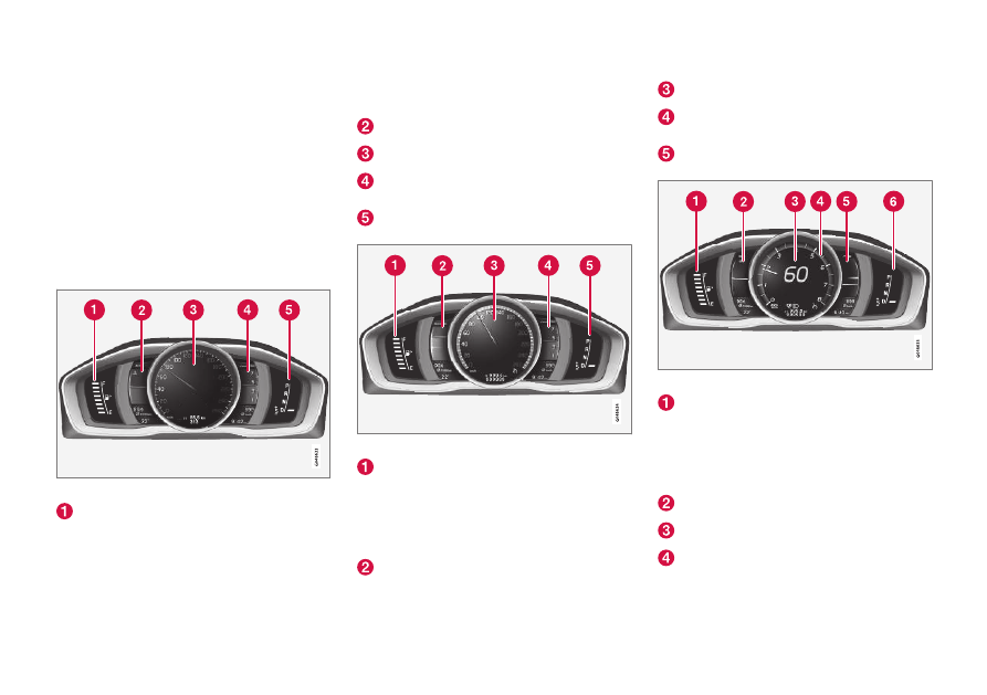
Gauges and indicators: digital
instrument panel

*

Different themes (display alternatives) can be
selected for the digital instrument panel:

Elegance

Eco

Performance

To change themes, press the OK button on the
left steering wheel lever and use the thumb
wheel to scroll to 

Themes

. Press OK to confirm

your choice.

Theme Elegance: gauges and indicators

Fuel gauge. When the indicator shows one
white marking, a yellow indicator light will illu-
minate to indicate a low fuel level. See also
Trip computer – introduction (p. 110) and

Refueling – fuel requirements (p. 277) for
additional information.
Coolant temperature gauge

Speedometer

Tachometer (engine speed in thousands of
revolutions per minute (rpm))
Gear indicator: Shows the currently selected
gear

Theme Eco: gauges and indicators

Fuel gauge. When the indicator shows a
white marking, a yellow indicator light will illu-
minate to indicate a low fuel level. See also
Trip computer – introduction (p. 110) and
Refueling – fuel requirements (p. 277) for
additional information.

Eco Guide (see Eco Guide

* and Power

Meter

* (p. 66))

Speedometer

Tachometer (engine speed in thousands of
revolutions per minute (rpm))
Gear indicator: Shows the currently selected
gear

Theme Performance: gauges and indicators

Fuel gauge. When the indicator shows a
white marking, a yellow indicator light will illu-
minate to indicate a low fuel level. See also
Trip computer – introduction (p. 110) and
Refueling – fuel requirements (p. 277) for
additional information.
Coolant temperature gauge

Speedometer

Tachometer (shows engine speed in thou-
sands of revolutions per minute (rpm))

INSTRUMENTS AND CONTROLS

* Option/accessory.

65

Power Meter (see Eco Guide

* and Power

Meter

* (p. 66)).

Gear indicator: Shows the currently selected
gear

Indicator and warning symbols

Indicator and warning symbols: analog instrument panel

Indicator symbols

Indicator and warning symbols

Warning symbols

Indicator and warning symbols: digital instrument panel

Indicator symbols

Indicator and warning symbols

Warning symbols

Function check

All indicator and warning symbols light up in igni-
tion mode II or when the engine is started. When
the engine has started, all the symbols should go
out except the parking brake symbol, which only
goes out when the brake is disengaged.

If the engine does not start or if the function
check is carried out in ignition mode II, all sym-
bols go out after 5 seconds except the malfunc-
tion indicator light, which may indicate a fault in
the vehicle's emissions system, and the symbol
for low oil pressure.

Some of the symbols shown may not be available
in all markets or models.

Related information

Instrument overview (p. 60)

Information displays – indicator symbols
(p. 67)

Information displays – warning symbols
(p. 69)

INSTRUMENTS AND CONTROLS

* Option/accessory.

66

Eco Guide* and Power Meter*

Eco guide and Power guide are two gauges in
the instrument panel that help improve driving
economy.

The vehicle also stores driving-related statistics
in the form of a bar graph, see Trip computer –
Trip statistics (p. 117).

Introduction

To display or remove these functions from the
instrument panel, select the "Eco" theme (see
Information displays – introduction (p. 63)).

Driving statistics are also stored and can be dis-
played in the form of a bar chart (see Trip com-
puter – Trip statistics (p. 117)).

Eco Guide

This gauge gives an indication of how economi-
cally the vehicle is being driven.

Current (instantaneous) reading

Average

Current (instantaneous) reading

This is the current level of economical driving; the
higher the reading, the more economically the
vehicle is being driven.

This value is calculated based on the vehicle's
speed, engine speed (rpm), engine load and
brake use.

The optimal speed range is between approxi-
mately 30–50 mph (50–80 km/h), preferably at
as low rpm as possible. The markers fall when
the brake or accelerator pedal is pressed.

If the current reading is very low, the red field in
the gauge will illuminate after a slight delay, indi-
cating low driving economy.

Average

The average reading changes gradually accord-
ing to changes in the current reading to indicate
how economically the vehicle has been driven
recently. The higher the average reading, the
more economically the vehicle has been driven.

Power Meter

This gauge indicates the engine power that has
been utilized and the amount of power remaining.

Available power

Utilized power

Available power

The smaller, upper indicator shows the engine's
available power

2

. The higher the reading on the

scale, the greater the amount of power remaining
in the current gear.

2

Depending on rpm

INSTRUMENTS AND CONTROLS

}}

* Option/accessory.

67

Utilized power

The larger, lower indicator shows the amount of
engine power that has been utilized

2

. The higher

the reading on the scale, the greater the amount
of power that is being utilized.

The larger the gap between the two indicators,
the greater the amount of power remaining.

Information displays – indicator

symbols

The indicator symbols alert the driver when cer-
tain functions are activated, that a system is
actively working or that a fault may have occur-
red in a system or function.

Symbol

Description

Fault in the Active Bending Light
(ABL)

*system

Malfunction indicator light

Anti-lock brake system (ABS)

Rear fog lights on

Stability system

The stability system's Sport mode is
activated

Low fuel level

Information symbol, read the text
displayed in the instrument panel

High beam indicator

Symbol

Description

Left turn signal indicator

Right turn signal indicator

Tire pressure monitoring sensor
(TPMS)

A

The Eco function is on.

TheStart/Stop function is active
(the engine has auto-stopped)

A

Option in Canada

Fault in the Active Bending Light (ABL)
system

This symbol will illuminate if there is a fault in the
ABL system. See Active Bending Lights (ABL)

*

(p. 86) for more information about this system.

2

Depending on rpm

||

INSTRUMENTS AND CONTROLS

* Option/accessory.

68

Malfunction Indicator Light

As you drive, a computer called On-Board Diag-
nostics II (OBDII) monitors your vehicle's engine,
transmission, electrical and emission systems.

The malfunction indicator light will illuminate if
the computer senses a condition that potentially
may need correcting. When this happens, please
have your vehicle checked by a trained and quali-
fied Volvo service technician as soon as possible.

A malfunction indicator light may have many cau-
ses. Sometimes, you may not notice a change in
your car's behavior. Even so, an uncorrected con-
dition could hurt fuel economy, emission controls,
and drivability. Extended driving without correct-
ing the cause could even damage other compo-
nents in your vehicle.

This light may illuminate if the fuel filler cap is not
closed tightly or if the engine was running while
the vehicle was refueled.

Anti-lock Brake System (ABS)

If the warning light comes on, there may be a
malfunction in the ABS system (the standard
braking system will still function). Check the sys-
tem by:

1. Stopping in a safe place and switching off

the ignition.

2. Restart the engine.

3. If the warning light goes off, no further action

is required.

If the indicator light remains on, the vehicle
should be driven to a trained and qualified Volvo
service technician for inspection, see Brakes –
general (p. 267) for additional information.

Rear fog lights

This symbol indicates that the rear fog lights are
on.

Stability system

This indicator symbol flashes when the stability
system is actively working to stabilize the vehicle,
see Stability system – introduction (p. 166) for
more detailed information.

Stability system - Sport mode

This symbol illuminates to indicate that the stabil-
ity system's Sport mode has been activated to
help provide maximum tractive force, for example
when driving with snow chains, or driving in deep
snow or loose sand.

Low fuel level

When this light comes on, the vehicle should be
refueled as soon as possible. See Refueling –
fuel requirements (p. 277) for information about
fuel and refueling.

Information symbol

The information symbol lights up and a text mes-
sage is displayed to provide the driver with nec-
essary information about one of the vehicle's sys-
tems. The message can be erased and the sym-
bol can be turned off by pressing the OK button
(see Information display – menu controls
(p. 108) for information) or this will take place

automatically after a short time (the length of
time varies, depending on the function affected).

The information symbol may also illuminate
together with other symbols.

High beam indicator

This symbol illuminates when the high beam
headlights are on, or if the high beam flash func-
tion is used.

Left turn signal indicator
Right turn signal indicator

NOTE

Both turn signal indicators will flash when
the hazard warning flashers are used.

If either of these indicators flash faster
than normal, the direction indicators are
not functioning properly.

Tire pressure monitoring system (TPMS)*

This symbol illuminates to indicate that tire pres-
sure in one or more tires is low, see Tire Pressure
Monitoring System (TPMS) – general information
(p. 310) for detailed information.

Eco* function on

The symbol will illuminate when the Eco function
is activated.

Start/stop*

The symbol illuminates when the engine has
auto-stopped.

INSTRUMENTS AND CONTROLS

}}

69

Related information

Information displays – introduction (p. 63)

Information displays – warning symbols
(p. 69)

Information displays – warning

symbols

The warning lights alert the driver that an impor-
tant function is activated or that a serious fault
has occurred.

Symbol

Description

Low oil pressure

A

Parking brake applied

B

SRS airbags

Seat belt reminder

Generator not charging

Fault in the brake system

Warning symbol, read the text dis-
played in the instrument panel

A

Certain engines do not use this symbol to indicate low oil pres-

sure. On these models, a text message will be displayed on the

instrument panel instead, see Engine compartment – engine oil

(p. 329).

B

The symbol is Park only on models with the optional digital

instrument panel.

Low oil pressure

If the light comes on while driving, stop the vehi-
cle, stop the engine immediately, and check the
engine oil level. Add oil if necessary. If the oil

level is normal and the light stays on after restart,
have the vehicle towed to the nearest trained and
qualified Volvo service technician.

Parking brake applied

This symbol flashes while the brake is being
applied and then glows steadily when the parking
brake has been set.

See Parking brake – general information (p. 271)
for more information about using the parking
brake.

Airbags – SRS

If this light comes on while the vehicle is being
driven, or remains on for longer than approxi-
mately 10 seconds after the vehicle has been
started, the SRS system's diagnostic functions
have detected a fault in a seat belt lock or pre-
tensioner, a front airbag, side impact airbag,
and/or an inflatable curtain. Have the system(s)
inspected by a trained and qualified Volvo service
technician as soon as possible.

See Supplemental Restraint System (SRS)
(p. 31) for more information about the airbag sys-
tem.

Seat belt reminder

This symbol comes on for approximately 6 sec-
onds if the driver has not fastened his or her seat
belt.

Generator not charging

This symbol comes on during driving if a fault has
occurred in the electrical system. Contact an
authorized Volvo workshop.

||

INSTRUMENTS AND CONTROLS

70

Engine temperature

Engine overheating can result from low oil or
coolant levels, towing or hard driving at high heat
and altitude, or mechanical malfunction. Engine
overheating will be signaled with text and a red
warning triangle in the middle of the instrument
display. The exact text will depend on the degree
of overheating. It may range from 

High engine

temp Reduce speed

 to 

High engine temp

Stop engine

. If appropriate, other messages,

such as 

Coolant level low, Stop safely

 will

also be displayed. If your engine does overheat
so that you must stop the engine, always allow
the engine to cool before attempting to check oil
and coolant levels.

See Engine compartment – coolant (p. 332) for
more information.

Fault in brake system

If this symbol lights, the brake fluid level may be
too low. Stop the vehicle in a safe place and
check the level in the brake fluid reservoir, see
Engine compartment – brake fluid (p. 333). If the
level in the reservoir is below MIN, the vehicle
should be transported to an authorized Volvo
workshop to have the brake system checked.

If the 

 and 

 symbols come on at

the same time, there may be a fault in the brake
force distribution system.

1. Stop the vehicle in a safe place and turn off

the engine.

2. Restart the engine.

If both symbols extinguish, continue driving.

If the symbols remain on, check the level in
the brake fluid reservoir, see Engine com-
partment – brake fluid (p. 333). If the brake
fluid level is normal but the symbols are still
lit, the vehicle can be driven, with great care,
to an authorized Volvo workshop to have the
brake system checked.

If the level in the reservoir is below MIN, the
vehicle should be transported to an author-
ized Volvo workshop to have the brake sys-
tem checked.

WARNING

If the fluid level is below the MIN mark in
the reservoir or if a warning message is
displayed in the text window: DO NOT
DRIVE. Have the vehicle towed to a
trained and qualified Volvo service techni-
cian and have the brake system inspec-
ted.

If the 

 and 

 symbols are

on at the same time, there is a risk of
reduced vehicle stability.

Warning symbol

The red warning symbol lights up to indicate a
problem related to safety and/or drivability. A
message will also appear in the instrument panel.
The symbol remains visible until the fault has
been rectified but the text message can be
cleared with the OK button, see Information dis-
play – menu controls (p. 108). The warning sym-
bol can also come on in conjunction with other
symbols.

Action:

1. Stop in a safe place. Do not drive the vehicle

further.

2. Read the information on the display. Imple-

ment the action in accordance with the mes-
sage in the display. Clear the message using
OK.

INSTRUMENTS AND CONTROLS

}}

71

Reminder – doors not closed

If one of the doors is not closed properly, the
information or warning symbol illuminates
(depending on the vehicle's speed), a graphic will
be displayed in instrument panel and an explana-
tory text message

3

 will also be displayed in the

instrument panel. Stop the vehicle in a safe place
as soon as possible and close the door.

If the vehicle is driven at a speed lower
than approximately 5 mph (7 km/h),
the information symbol illuminates.

If the vehicle is driven at a speed
higher than approximately 5 mph
(7 km/h), the warning symbol illumi-

nates.

If the hood is not closed properly, the warning
symbol illuminates, a graphic will be displayed in
instrument panel and an explanatory text mes-
sage

3

 will also be displayed in the instrument

panel. Stop the vehicle in a safe place as soon as
possible and close the hood.

If the trunk is not closed properly, the informa-
tion symbol illuminates and a graphic will be dis-
played in instrument panel. Stop the vehicle in a
safe place as soon as possible and close the
trunk.

Related information

Information displays – introduction (p. 63)

Information displays – indicator symbols
(p. 67)

Engine compartment – coolant (p. 332)

My Car – introduction

The MY CAR menu system provides access to
menus for operating many of the vehicle's func-
tions, such as setting the clock, door mirrors,
lock and alarm settings, etc.

Some of the features or functions are standard;
others are optional and vary according to model/
market.

Operation

Use the buttons on the center console or the
steering wheel keypad to navigate in the menus.

3

Text message applies only to models with the optional digital instrument panel

||

INSTRUMENTS AND CONTROLS

* Option/accessory.

72

The center console control panel and the steering wheel
keypad. The illustration is generic and the appearance/
location of the buttons may vary.

MY CAR: opens the MY CAR menu system.

OK/MENU: Press the button on the center
console or the thumb wheel on the steering
wheel keypad to select a menu alternative or
to store a selected function in the system's
memory.
TUNE: Turn this control on the center con-
sole or the thumb wheel on the steering
wheel keypad to navigate up/down in a
menu.
EXIT

EXIT functions

Depending on which function the cursor is point-
ing to and the menu level, briefly pressing EXIT
will result in:

An in-coming phone call will be rejected

The current function will be cancelled

Characters entered will be erased

The most recent selection will be cancelled

Go back/up in the menu system

Pressing and holding EXIT takes you to the nor-
mal view for MY CAR. If you are already in normal
view, this will take you to the main source menu.

Menu selections and paths

Please consult your Sensus Infotainment supple-
ment for a description of the MY CAR menu
selections and paths.

Information displays – ambient

temperature sensor

Location of the ambient temperature sensor, A: digital
instrument panel

*, B: analog instrument panel

NOTE

When the ambient temperature is between
23° and 36 °F (–5° and +2 °C), a snowflake
symbol will be displayed next to the tempera-
ture. This symbol serves as a warning for pos-
sible slippery road surfaces. Please note that
this symbol does not indicate a fault with your
vehicle.

At low speeds or when the vehicle is not mov-
ing, the temperature readings may be slightly
higher than the actual ambient temperature.

Related information

Information displays – introduction (p. 63)

INSTRUMENTS AND CONTROLS

}}

* Option/accessory.

73

Information displays – trip odometer

and clock

The trip odometers 

T1

 and 

T2

 and clock are dis-

played in the instrument panel.

Trip odometers

Trip odometer

4

Odometer display

Turn the thumb wheel on the left steering wheel
lever to display the desired trip odometer.

Press and hold the RESET button on the left
steering wheel lever for at least 1 second to
reset the selected trip odometer

5

.

Clock

Clock, digital instrument panel

*

Display

6

Setting the clock

The clock can be set in the MY CAR menu sys-
tem. See My Car – introduction (p. 71) for addi-
tional information about these menus.

Go to 

Settings

System options

Time

settings

. Set 

Auto time

 to ON (check the box)

and select the correct time zone under 

Location

.

Related information

Information displays – introduction (p. 63)

Inserting/removing remote key

The remote key is used to start the engine or to
use various electrical functions without starting
the engine.

Inserting and removing the remote key

Ignition slot with remote key and START/STOP

ENGINE button.

Inserting the remote key

7

Holding the end of the remote key with the base
of the key blade, insert the remote key into the
ignition slot as shown in the illustration and press
it in as far as possible.

4

The trip odometer will be displayed differently in analog and digital instrument panels

5

Models with a digital information panel: press and hold RESET for more than approximately 4 seconds to reset all trip computer information

6

Models with an analog instrument panel: the time will be displayed in the center of the instrument panel

7

Not necessary in vehicles with the optional keyless drive.

||

INSTRUMENTS AND CONTROLS

* Option/accessory.

74

CAUTION

Foreign objects in the ignition slot can impair
function or cause damage.

Removing the remote key

The remote key can be removed from the ignition
slot by pulling it out.

Related information

Ignition modes (p. 74)

Ignition modes

The vehicle's ignition has 3 modes: 

0, I, and II

that can be used without starting the engine.
The following table shows examples of which
functions are available in the respective modes.

NOTE

To access ignition modes I or II without star-
ting the engine, the brake pedal must not be
depressed.

Mode

Function

0

The odometer, clock and temperature
gauge are illuminated. Power seats

*

can be adjusted and the infotainment
system can be used for a limited time
(to minimize battery drain, see the
Sensus Infotainment Supplement).

I

The Moonroof

*, power windows,12-

volt sockets in the passenger com-
partment, navigation system

*, climate

system blower, windshield wipers can
be used.

II

The headlights/taillights illuminate.
Warning/indicator lights illuminate for
5 seconds. Other systems are acti-
vated. However, the heated seats

* and

heated rear window function can only
be activated when the engine is run-
ning. Mode II should only be used
for very short periods to help avoid
draining the battery.

Ignition modes

Ignition mode 0

The vehicle is unlocked.

INSTRUMENTS AND CONTROLS

* Option/accessory.

75

Ignition mode I

With the remote key fully pressed into the
ignition slot

8

, press START/STOP ENGINE

briefly.

Ignition mode II

With the remote key fully pressed into the
ignition slot

8

, press START/STOP ENGINE

for approximately 2 seconds.

Returning to mode 0

To return to mode 0 from mode II or I, press
START/STOP ENGINE briefly.

Starting and stopping the engine

See Starting the engine (p. 250) and Switching
off the engine (p. 252) for information on star-
ting the engine and switching it off.

Emergency towing

See Towing the vehicle (p. 286) for important
information about the remote key when the vehi-
cle is being towed.

Related information

Inserting/removing remote key (p. 73)

Front seats

The front seats can be adjusted in a number of
ways to help provide the most comfortable seat-
ing position.

Raise/lower the seat, pump up/down.

Front-rear adjustment: lift the bar and move
the seat to the position of your choice.
Raise/lower front edge of seat cushion,
pump up/down.
Backrest tilt: turn the control to adjust the
angle of the backrest.

Electronic lumbar support

*. Press the button

to adjust.

Control panel for power seat

*, see Front

seats – power seat (p. 76).

WARNING

Do not adjust the seat while driving. The
seat should be adjusted so that the brake
pedal can be depressed fully. In addition,
position the seat as far rearward as com-
fort and control allow.

Check that the seat is securely locked
into position after adjusting.

Related information

Front seats – power seat (p. 76)

Rear seats – folding backrest (p. 81)

Rear seats – head restraints (p. 79)

8

Not necessary in vehicles with the optional keyless drive.

INSTRUMENTS AND CONTROLS

* Option/accessory.

76

Front seats – folding backrest*

9

The front passenger's seat backrest can be
folded down to make it easier to transport long
objects.

The front passenger seat backrest can be folded
to a horizontal position to make room for a long
load. Fold the backrest as follows:

Move the seat as far back and down as pos-
sible.

Adjust the backrest to an upright position.

Lift the catches on the rear of the backrest.

Without releasing the catches, push the
backrest forward.

Move the seat as far forward as possible so
that the head restraint slides under the glove
compartment.

Return the seat to its upright position in the
reverse order.

WARNING

When transporting long objects, cover
sharp edges on the load to help prevent
injury to occupants. Secure the load to
help prevent shifting during sudden stops.

When the seat's backrest is returned to
the upright position, push and pull it to be
sure that it is securely locked in this posi-
tion.

Related information

Front seats (p. 75)

Front seats – power seat (p. 76)

Rear seats – folding backrest (p. 81)

Rear seats – head restraints (p. 79)

Front seats – power seat

10

The power seat(s) can be adjusted for a short
period after unlocking the door with the remote
control without the key in the ignition slot. Seat
adjustment is normally made when the ignition is
on and can always be made when the engine is
running.

Power seat

Power seat adjustment controls

Front edge of seat cushion up/down

Raise/lower the seat

Seat forward/rearward

Backrest tilt

Electronic lumbar support

*

9

The front passenger's seat backrest on models equipped with the optional sport seat cannot be folded down

10

Optional on certain models

INSTRUMENTS AND CONTROLS

* Option/accessory.

77

Operation

NOTE

Only one of the power seat's controls can
be used at the same time.

The power seats have an overload pro-
tector that activates if a seat is blocked
by any object. If this occurs, switch off the
ignition (key in position 0) and wait for a
short period before operating the seat
again.

Power seat memory function

Power seat memory buttons

Button for storing a position

Button for storing a position

Button for storing a position

M (memory) button

Programming the seat's memory

Three different seating and door mirror positions
can be stored in the driver seat's memory.

The following example explains how button (1)
can be programmed. Buttons (2) and (3) are pro-
grammed in the same way.

To program (store) a seat and door mirror posi-
tion in button (1):

1. Move the seat (and door mirrors) to the

desired positions using the seat and mirror
adjustment controls.

2. Press and hold down the M (memory) button

(4).

3. With the memory button depressed, press

button (1) briefly to store the current position
for the seat/mirrors.

To move the seat and mirrors to the position
that they were in when a button was pro-
grammed:

Press and hold down button (1) until the
seat and mirrors stop moving.

NOTE

As a safety precaution, the seat will stop
automatically if the button is released before
the seat has reached the preset position.

Heated seats

*

See Heated seats (p. 126).

Related information

Front seats (p. 75)

Rear seats – folding backrest (p. 81)

Rear seats – head restraints (p. 79)

INSTRUMENTS AND CONTROLS

* Option/accessory.

78

Key memory – power driver's seat*

and door mirrors

Each remote key has a memory that enables it to
store (remember) the position of the power driv-
er's seat and door mirrors when the vehicle is
locked with that remote key.

Remote key memory and the power
driver's seat

* and door mirrors

11

The key memory has to be activated for each of
the remote keys used in the vehicle as fol-
lows:

1. Insert a remote key in the ignition slot.

2. Go into the MY CAR menu and go to

Settings

Car settings

Car key

memory

3. To activate the remote key memory feature,

press ENTER (check the box).
> The remote key is now ready to store the

position of the power driver's seat and
door mirrors.

Repeat this procedure for each of the vehicle's
remote keys.

See My Car – introduction (p. 71) for a descrip-
tion of the menu system.

Storing the positions of the power driver's
seat/mirrors in the remote key

1. Move the seat and door mirrors to the

desired position using the seat and mirror
adjustment controls.

2. Exit the vehicle and lock the doors with the

remote key (or close the driver's door and
press the lock button on the door handle
with the remote key in your possession on
vehicles with the optional keyless drive).
> The positions of the power driver's seat

and door mirrors are now stored in the
remote key's memory.

NOTE

The remote key's memory feature and the
power driver's seat memory function (the set-
tings made using the buttons on the side of
the seat, see the section "Power seat mem-
ory function" in Front seats – power seat
(p. 76)) work independently of each other.

11

This information also applies to vehicles with the optional keyless drive.

INSTRUMENTS AND CONTROLS

}}

79

Returning the seat/mirrors to the stored
positions

To move the seat and door mirrors to the position
stored in the remote key:

1. Unlock the driver's door with the same

remote key (the one used to lock the doors).
For models equipped with the optional key-
less drive, you must have the same remote
key in your possession.

2. Open the driver's door within 2 minutes.

The driver's seat and door mirrors will automati-
cally move to the position in which you left them
(if the vehicle has been unlocked with one of the
other keys and new seat/mirror adjustments have
been made).

NOTE

The seat will move to this position even if
someone else has moved it to a different
position and locked the vehicle with a dif-
ferent remote key.

This feature will work in the same way
with all of the remote keys that you use
with your vehicle.

Emergency stop

WARNING

Because the driver's seat can be adjusted
with the ignition off, children should never
be left unattended in the vehicle.

Movement of the seat can be STOPPED
at any time by pressing any button on the
power seat control panel.

Do not adjust the seat while driving. The
seat should be adjusted so that the brake
pedal can be depressed fully. In addition,
position the seat as far rearward as com-
fort and control allow.

The seat rails on the floor must not be
obstructed in any way when the seat is in
motion.

Related information

Remote key – functions (p. 147)

Rear seats – head restraints

The rear seat head restraints can be folded
down. The center head restraint can be raised/
lowered according to the passenger's height.

Rear center head restraint


Content   ..  2  3  4  5   ..