Suzki Burgman AN400. Manual - part 34


  Index      Motorcycles     Suzki Burgman AN400 - service and repair manual 2002 year


Search            


Content   ..  32  33  34  35   ..


Suzki Burgman AN400. Manual - part 34


4-18     FI SYSTEM

FI SYSTEM TROUBLESHOOTING

CUSTOMER COMPLAINT ANALYSIS

Record details of the problem (failure, complaint) and how it occurred as described by the customer. For this
purpose, use of such an inspection form will facilitate collecting information to the point required for proper
analysis and diagnosis.

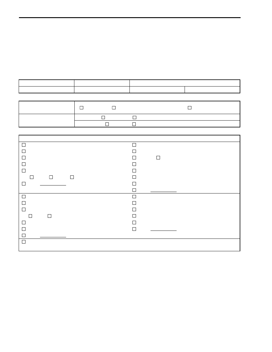
EXAMPLE: CUSTOMER PROBLEM INSPECTION FORM

User name:

Model:

VIN:

Date of issue:

Date Reg.

Date of problem:

Mileage:

Malfunction indicator 
lamp condition (LED)


Always ON  


Sometimes ON  


Always OFF  


Good condition

Malfunction display/code 
(LCD)

User mode: 

 No display   

 Malfunction display (                 )

Dealer mode: 

 No code  


Malfunction code (                 )

PROBLEM SYMPTOMS


 Difficult Starting


 Poor Driveability


 No cranking


Hesitation on acceleration


No initial combustion


 Back fire/

 After fire


No combustion


Lack of power


Poor starting at


(


cold   


warm  


always)


Surging


Abnormal knocking


Other                     


Engine rpm jumps briefly


Other                     


Poor Idling


Engine Stall when


Poor fast Idle


Immediately after start


Abnormal idling speed


(


High  


Low) (         r/min)


Throttle valve is opened


Throttle valve is closed


Unstable


Load is applied


Hunting (         r/min. to         r/min)


Other                     


Other                     


OTHERS:

FI SYSTEM     4-19

NOTE:
* The above form is a standard sample. It should be modified according to conditions characteristic of each

market.

MOTORCYCLE/ENVIRONMENTAL CONDITION WHEN PROBLEM OCCURS

Environmental condition

Weather
Temperature
Frequency


 Fair   

 Cloudy   

 Rain   

 Snow   

 Always   

 Other


 Hot   

 Warm   

 Cool   

 Cold (         °F/        °C)   

 Always


 Always   

 Sometimes (         times/        day, month)   

 Only once


 Under certain condition

Road


 Urban   

 Suburb   

 Highway   

 Mountainous (

 Uphill   

 Downhill)


 Tarmacadam   

 Gravel   

 Other

Motorcycle condition

Engine condition


 Cold   

 Warming up phase   

 Warmed up   

 Always   

 Other at starting


 Immediately after start   

 Racing without load   

 Engine speed (     r/min)

Motorcycle con-
dition

During driving:   

 Constant speed   

 Accelerating   

 Decelerating


 Right hand corner   

 Left hand corner   

 At stop


 Motorcycle speed when problem occurs (         km/h,         Mile/h)


Other


4-20     FI SYSTEM

SELF-DIAGNOSTIC PROCEDURES

• Don’t disconnect couplers from ECM, battery cable from bat-

tery, ECM ground wire harness from engine or main fuse
before confirming malfunction code (self-diagnostic trouble
code) stored in memory. Such disconnection will erase mem-
orized information in ECM memory.

• Malfunction code stored in ECM memory can be checked by

the special tool.

• Before checking malfunction code, read SELF-DIAGNOSIS

FUNCTION “USER MODE and DEALER MODE” (

#

4-14,

15) carefully to have good understanding as to what functions
are available and how to use it.

• Be sure to read “PRECAUTIONS for Electrical Circuit Ser-

vice” (

#

4-2) before inspection and observe what is written

there.

• Remove the front leg shield cover.
• Connect the special tool to the dealer mode coupler 


A

 at the

wiring harness, and start the engine or crank the engine for
more than 4 seconds.

• Turn the special tool’s switch ON and check the malfunction

code to determine the malfunction part.

!

09930-82720: Mode select switch

SELF-DIAGNOSIS RESET PROCEDURE

• After repairing the trouble, turn OFF the ignition switch and

turn ON again.

• If the malfunction code indicates (C00), the malfunction is

cleared.

• Disconnect the special tool from the dealer mode coupler.

ON

OFF

FI SYSTEM     4-21

MALFUNCTION CODE AND DEFECTIVE CONDITION

MALFUNCTION

CODE

DETECTED ITEM

DETECTED FAILURE CONDITION

CHECK FOR

C00

NO FAULT

–––––––––––

C12

Crankshaft position 
sensor

The signal does not reach ECM for more than 3 sec. after 
receiving the starter signal.
The crankshaft position sensor wiring and mechanical parts.
(Crankshaft position sensor, wiring/coupler connection)

C13

Intake air pressure 
sensor

The sensor should produce following voltage.

(0.30 V 

 sensor voltage < 4.45 V)

Without the above range, C13 is indicated.
Intake air pressure sensor, wiring/coupler connection.

C14

Throttle position sen-
sor

The sensor should produce following voltage.

(0.45 V 

 sensor voltage < 4.80 V)

Without the above range, C14 is indicated.
Throttle position sensor, wiring/coupler connection.

C15

Engine coolant tem-
perature sensor

The sensor voltage should be the following.

(0.20 V 

 sensor voltage < 4.80 V)

Without the above range, C15 is indicated.
Engine coolant temperature sensor, wiring/coupler connection.

C21

Intake air temperature 
sensor

The sensor voltage should be the following.

(0.20 V 

 sensor voltage < 4.80 V)

Without the above range, C21 is indicated.
Intake air temperature sensor, wiring/coupler connection.

C23

Tip over sensor

The sensor voltage should be the following for more than 2 sec. 
after ignition switch turns ON.

(0.40 V 

 sensor voltage < 4.60 V)

Without the above value, C23 is indicated.
Tip over sensor, wiring/coupler connection.

C24

Ignition signal

Crankshaft position sensor (pick-up coil) signal is produced but 
signal from ignition coil is interrupted continuous by 2 times or 
more. In this case, the code C24 is indicated.
Ignition coil, wiring/coupler connection, power supply from the 
battery.

C32

Fuel injector

Crankshaft position sensor (pick-up coil) signal is produced but 
fuel injector signal is interrupted continuous by 2 times or more. 
In this case, the code C32 is indicated.
Injector, wiring/coupler connection, power supply to the injector.

C40

Idle air control (IAC) 
valve

No IAC valve voltage is supplied after starting the engine.
IAC valve, wiring/coupler connection.

C41

Fuel pump relay

No voltage is applied to fuel pump although fuel pump relay is 
turned ON, or voltage is applied to fuel pump although fuel 
pump relay is turned OFF.
Fuel pump relay, connecting lead, power source to fuel pump 
relay.

C42

Ignition switch

Ignition switch signal is not input in the ECM.
Ignition switch, lead wire/coupler.


Content   ..  32  33  34  35   ..